Table of Contents
Advertisement
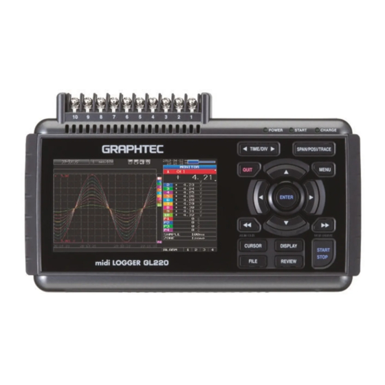
midi LOGGER
GL220
Thank you for choose the midi LOGGER GL220.
This Quick Start Guide describes the basic operations.
Please refer to the manual (PDF) in the CD-ROM for more information.
Checking the Outer Casing
After unpacking, check the GL220's Exterior to make sure that
there are no crack or other damage before use.
Checking the Accessories
o Quick Start Guide : 1
o CD-ROM : 1
o AC cable/AC adapter : 1
Setting and Checking the AC Line Frequency
Set the AC line frequency in the "OTHR" menu. This setting
(50 or 60 Hz) affects the noise reduction performance of the device.
Quick Start Guide
Don't forget to
check the setting
GL220-UM-851
Advertisement
Table of Contents

Related Manuals for GRAPHTEC midi LOGGER GL220

Summary of Contents for GRAPHTEC midi LOGGER GL220
- Page 1 This Quick Start Guide describes the basic operations. Please refer to the manual (PDF) in the CD-ROM for more information. Checking the Outer Casing After unpacking, check the GL220's Exterior to make sure that there are no crack or other damage before use. Checking the Accessories...
-
Page 2: Table Of Contents
GL220 Contents Nomenclature................Connection Procedures.............. Precautions to Observe When Performing Measurement ....Descriptions of the Control Panel Keys ........Descriptions of the Menu Screens ..........Measurement Procedure..............1. Preparations : How to Make the Preparations Required for Data Capture .......... -
Page 3: Nomenclature
GL220 Nomenclature Top Panel Monitor Analog signal input terminals Control panel keys Power switch Connecting the USB memory device Power jack for the humidity sensor GND terminal (Humidity sensor is the option B-530) Operation status LED -POWER External input/output terminals... -
Page 4: Connection Procedures
"DC LINE" on the GL220. connector indicated as "DC LINE" on the GL220. GL220. Connect the other end of the cable to ground. Making Connections to the Analog Input Terminals CH 1 2 3 4 5 6 7 8 9 10... -
Page 5: Precautions To Observe When Performing Measurement
Ex 3 : In the AMP settings menu, set filter to any setting other than "OFF". Ex 4 : Operate GL220 with batteries (Option: B-517). Ex 5: Set the sampling interval which enables GL220’s digital filter (see table below). Number of Measuring... -
Page 6: Descriptions Of The Control Panel Keys
TRACE Used to change trace settings (set the waveform display to On or Off). Note: If the QUIT key is pressed when the GL220 is in the SPAN, POSITION, or TRACE mode, the display returns to MONITOR mode. . TIME/DIV... - Page 7 MENU Press the MENU key to open a setup menu. Each time this key is pressed, the setup screen tabs change in the sequence shown below. - AMP Settings Used to set the input, range, filter and other settings. - Data Capture Settings DATA Used to set settings such as the sampling interval, data capture destination, and calculations during data capture.
- Page 8 Press the START/STOP key to perform start and stop of a data capture while the GL220 is in the Free Running status. If this key is held down while the power to the GL220 is turned on, the GL220 goes into USB Drive Mode.
-
Page 9: Descriptions Of The Menu Screens
GL220 Descriptions of the Menu Screens 4.Device access lamp 3.Status mark 5.Remote lamp 8.AC/Battery status indicator 6.Key lock lamp 1.Status message display area 2.Time/DIV display area 7.Clock display 9.Waveform operation 18.Data capture bar display area 10.Digital display area 17.Scale upper limit 16.Waveform display area... -
Page 10: Measurement Procedure
GL220 Measurement Procedure In this section we will provide a simple explanation of the data capture procedure: Preparations -> Setup -> Data Capture -> Data Replay. Voltage measurement is performed here. Purpose of data capture : To measure the temperature of the target objects... -
Page 11: Setup: How To Make The Settings
2. Setup: How to Make the Settings Make the settings required for data capture. Here we will make only those settings that are minimum requirement. The other settings will be not changed from the factory default settings. Basic Setup Menu Operation key, the ENTER key, and the QUIT key are used to set the condition on the setup menu. - Page 12 (3) The file settings box shown in the following screen opens. This box is used to specify file names for the GL220's internal memory and for the USB memory device. file names for the GL220's internal memory and for the USB memory device.
- Page 13 (6) Return to screen (2) and move the cursor to the icon to select the created folder and then press the ENTER key. folder and then press the ENTER key. (7) Move the cursor to and then press the ENTER key. ...
-
Page 14: Data Capture: How To Capture Data
(2) A confirmation message is displayed. Press the ENTER key. (2) A confirmation message is displayed. Press the ENTER key. (3) Data capture ends, and the GL220 goes into the Free Running status. The operation of data capture is completed. -
Page 15: Data Replay : How To Replay Captured Data
Data replay ends, and the GL220 goes into the Free Running status. Data replay ends, and the GL220 goes into the Free Running status. Explanation of basic operation in the GL220 is completed. The GL220 has many other convenient functions. Please refer the next five pages for details. -
Page 16: Convenient Functions
GL220 Convenient Functions The GL220 has various functions that enable it to be used more effectively. The selected three functions are described with details in the following. Trigger Functions to Control Data Capture Start/Stop Operations Trigger functions can be used to control the timing of the start of a data capture operation, and the timing of the end of a data capture operation. - Page 17 GL220 to the Free Running status. (8) Press the START/STOP key to start data capture. If the trigger condition has not been satisfied, the GL220 goes into the "Armed" status as shown on the following screen. as shown on the following screen.
-
Page 18: Span, Position And Trace Functions To Adjust The Waveform Display
Points to The span, position and trace operations can be performed while the GL220 Remember is in the Free Running status, while it capturing data, and while it is replaying data. -
Page 19: Specifications
GL220 Specifications Standard Specifications Item Description Number of analog Channels External input and Trigger input and External sampling (1ch), output functions Logic input (4ch) or Pulse input (4ch), Alarm output (4ch) PC interface USB (FullSpeed supported) provided as standard features Built-in memory Internal memory: Approx. -
Page 20: Input Unit Specifications
Input Unit Specifications Item Description M3 screw type, 10 channels Number of input channels Photo MOS relay scanning system, Method all channels isolated, balanced input 10ms/1ch Maximum sampling speed 20m/50m/100m/200m/500m Voltage 1/2/5/10/20/50/1-5V F.S. Measurement K、J、E、T、R、S、B、N、W(WRe5-26) accuracy Temperature 0 to 100% (voltage 0 V to 1 V scaling conversion) Humidity *with B-530 (option) Voltage... -
Page 21: Installation Guide
Note: D: drive name of CD-ROM. The letter of CD-ROM drive vary it with the CD-ROM drive of your PC. To Install GL220 Application Software To install the application software which sets and controls the GL220, follow the directions below. 1. Insert the accompanying midi LOGGER GL220 CD-ROM in the PC's CD drive. - Page 22 Specifications are subject to change without notice. May 1, 2010 GL220 Quick Start Guide 1st edition-01 (GL220-UM-851) Publisher GRAPHTEC CORPORATION...
Need help?
Do you have a question about the midi LOGGER GL220 and is the answer not in the manual?
Questions and answers