Universal Robots UR5e User Manual
Hide thumbs
Also See for UR5e:
- User manual (195 pages) ,
- Original instructions manual (291 pages) ,
- Service manual (205 pages)
Advertisement
Quick Links
Advertisement

Related Manuals for Universal Robots UR5e


Summary of Contents for Universal Robots UR5e
- Page 1 User Manual UR5e Original instructions (en) PolyScope 5...
- Page 2 UR5e User Manual...
- Page 3 Universal Robots A/S. This document is periodically reviewed and revised. Universal Robots A/S assumes no responsibility for any errors or omissions in this document. Copyright © 2009–2024 by Universal Robots A/S. The Universal Robots logo is a registered trademark of Universal Robots A/S. User Manual UR5e...
- Page 4 UR5e User Manual...
-
Page 5: Table Of Contents
Contents 1. Liability and Intended Use 1.1. Limitation of Liability 1.2. Intended Use 2. Your Robot 2.1. Technical Specifications UR5e 2.2. Maximum Payload 2.3. Stopping Time and Stopping Distance 2.4. PolyScope Overview 2.4.1. Icons/Tabs On PolyScope 3. Safety 3.1. General 3.2. Safety Message Types 3.3. - Page 6 10.3.1. Setting a Software Safety Password 10.3.2. Changing the Software Safety Configuration 10.3.3. Applying a New Software Safety Configuration 10.3.4. Safety Configuration without Teach Pendant 10.3.5. Software Safety Modes 10.3.6. Software Safety Limits 10.3.7. Safe Home Position UR5e User Manual...
- Page 7 11.3. Cybersecurity Hardening Guidelines 11.4. Passwords 11.5. Password Settings 11.6. Administrator Password 11.7. Operational Password 12. Communication Networks 12.1. Fieldbus 12.2. MODBUS 12.3. EtherNet/IP 12.4. PROFINET 12.5. PROFIsafe 13. Emergency Events 13.1. Emergency Stop 13.2. Movement Without Drive Power 13.3. Modes User Manual UR5e...
- Page 8 15.2. Robot Arm Cleaning and Inspection 15.3. Log Tab 15.4. Program and Installation Manager 15.5. Accessing Robot Data 16. Disposal and Environment 17. Declarations and Certificates (original EN) 18. Declarations and Certificates 19. Safety Functions Table 19.1. Table 1a 19.2. Table 2 20. Certifications 21. Certificates UR5e User Manual...
- Page 9 User Manual UR5e...
-
Page 10: Liability And Intended Use
Read and follow the recommendations for intended use and the specifications provided in the User Manual. Universal Robots robots are intended for industrial use, to handle tools/end effectors and fixtures, or to process or transfer components or products. For details about the conditions under which the robot should operate, see Declarations and Certificates and the technical specifications. - Page 11 UR robots or UR products. • Misuse is prohibited as the result could be death, personal injury, and /or property damage UNIVERSAL ROBOTS EXPRESSLY DISCLAIMS ANY EXPRESS OR IMPLIED WARRANTY OF FITNESS FOR ANY PARTICULAR USE. WARNING Do not modify the robot.
- Page 12 • Your application risk assessment shall include the risks associated with the application's reach, motion, payload and speed of the robot, end effector and workpiece. UR5e User Manual...
-
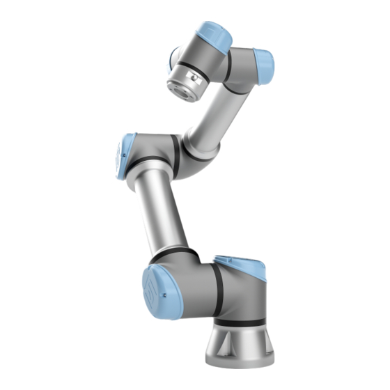
Page 13: Your Robot
2. Your Robot 2. Your Robot Introduction Congratulations on the purchase of your new Universal Robots robot, which consists of the robot arm (manipulator), Control Box and the Teach Pendant. Originally designed to mimic the range of motion of a human arm,... - Page 14 Wrist 1 and Wrist 2: make finer movements. • Wrist 3: where the tool is attached to the Tool Flange. The robot is partly completed machinery, as such a Declaration of Incorporation is provided. A risk assessment is required for each robot application. UR5e User Manual...
- Page 15 Sign into myur.universal-robots.com to access the portal. In the myUR portal, your cases are handled either by your preferred distributor, or escalated to Universal Robots Customer Service teams. You can also subscribe to robot monitoring and manage additional user accounts in your company.
- Page 16 Manuals, guides and handbooks can be read online. We have gathered a large number of documents at https://www.universal-robots.com/manuals • PolyScope Software Handbook with descriptions and instructions for the software • The Service Handbook with instructions for troubleshooting, maintenance and repair • The Script Directory with scripting for in depth programming UR5e User Manual...
-
Page 17: Technical Specifications Ur5E
2. Your Robot 2.1. Technical Specifications UR5e Robot type UR5e Robot weight 20.7 kg / 45.7 lb Maximum payload 5 kg / 11 lb (Mechanical Interface) Reach 850 mm / 33.5 in Unlimited rotation of tool flange, ± 360 ° for all other joints Joint ranges ± 360 ° for all joints Joints: Max 180 °/s . -
Page 18: Maximum Payload
• Payload mass • Center of gravity • Inertia You can use the URSim to evaluate the accelerations and cycle times of the robot motions with a specific payload. 2.3. Stopping Time and Stopping Distance UR5e User Manual... - Page 19 The Y-axis is the distance from where the stop is initiated to the final position. The payload CoG is at the tool flange. Joint 0 (BASE) Stopping distance in meters for 33% of 5kg Stopping distance in meters for 66% of 5kg User Manual UR5e...
- Page 20 Stopping distance in meters for maximum payload of 5kg Joint 0 (BASE) Stopping time in seconds for 33% of 5kg Stopping time in seconds for 66% of 5kg Stopping time in seconds for maximum payload of 5kg UR5e User Manual...
- Page 21 (SHOULDER) Stopping distance in meters for 33% of 5kg Stopping distance in meters for 66% of 5kg Stopping distance in meters for maximum payload of 5kg Joint 1 (SHOULDER) Stopping time in seconds for 33% of 5kg User Manual UR5e...
- Page 22 2. Your Robot Stopping time in seconds for 66% of 5kg Stopping time in seconds for maximum payload of 5kg Joint 2 (ELBOW) Stopping distance in meters for 33% of 5kg Stopping distance in meters for 66% of 5kg UR5e User Manual...
- Page 23 2. Your Robot Stopping distance in meters maximum payload of 5kg Joint 2 (ELBOW) Stopping time in seconds for 33% of 5kg Stopping time in seconds for 66% of 5kg Stopping time in seconds for maximum payload of 5kg User Manual UR5e...
-
Page 24: Polyscope Overview
For best results, use the tip of your finger to make a selection on the screen. In this manual, this is referred to as a "tap". A commercially available stylus may be used to make selections on the screen if desired. UR5e User Manual... -
Page 25: Icons/Tabs On Polyscope
Manual indicates the operational mode of the robot is set to Manual. Tap it to switch to the Automatic operational mode. Remote Control The Local mode and Remote mode icons only become accessible if you enable Remote Control. User Manual UR5e... - Page 26 High Speed High Speed Manual Mode is a hold-to-run function, only available in Manual mode Manual Mode when a Three-Position Enabling Device is configured. High Speed Manual Modeallows both tool speed and elbow speed to temporarily exceed 250mm/s. UR5e User Manual...
-
Page 27: Safety
It is essential to observe and follow all assembly instructions in the following sections of this manual. NOTICE Universal Robots disclaims any and all liability if the robot (arm Control Box with or without Teach Pendant) is damaged, changed or modified in any way. Universal Robots cannot be held responsible for... -
Page 28: Safety Message Types
Indicates a hazardous situation that, if not avoided, can result in injury. GROUND Indicates grounding. PROTECTIVE GROUND Indicates protective grounding. NOTICE Indicates the risk of damage to equipment and/or information to be noted. READ MANUAL Indicates more detailed information that should be consulted in the manual. UR5e User Manual... -
Page 29: General Warnings And Cautions
Adhere to the requirements and guidance in ISO 10218-2. WARNING Handling tools/end effectors with sharp edges and/or pinch points can result in injury. • Make sure tools/end effectors have no sharp edges or pinch points. • Protective gloves and/or protective eyeglasses could be required. User Manual UR5e... - Page 30 • Read the commissioning information. NOTICE Very strong magnetic fields can damage the robot. • Do not expose the robot to permanent magnetic fields. READ MANUAL Verify all mechanical and electrical equipment is installed according to relevant specifications and warnings. UR5e User Manual...
-
Page 31: Integration And Responsibility
*Stop the robot with power available to the drives, while maintaining the trajectory. Drive power is maintained after the robot is stopped. *Universal Robots robots’ Category 2 stops are further described as SS1 or as SS2 type stops according to IEC 61800-5-2. -
Page 32: Risk Assessment
A part of the risk assessment is to determine the safety configuration settings, as well as the need for additional emergency stops and/or other protective measures required for the specific robot application. UR5e User Manual... - Page 33 Stopping Distance Limit: Used to limit the stopping distance of the robot. If either of the above is used, there is no need for manually performed periodic stopping performance testing. The robot safety control does continuous monitoring. User Manual UR5e...
- Page 34 • Likelihood of occurrence • Possibility to avoid the hazardous situation Potential Universal Robots identifies the potential significant hazards listed below for Hazards consideration by the integrator. Other significant hazards can be associated with a specific robot application. • Penetration of skin by sharp edges and sharp points on tool/end effector or tool/end effector connector.
-
Page 35: Pinch Hazard
One area (left) is defined for radial motions when the wrist 1 joint is at least 750 mm from the base of the robot. The other area (right) is within 200 mm of the base of the robot, when moving tangentially. User Manual UR5e... -
Page 36: Lifting And Handling
While in use, all cables are to be coiled and held to prevent tripping hazards. 5.2. Robot Arm Description The robot arm, depending upon weight, can be carried by one or two people unless the sling is provided. If the sling is provided, equipment for lifting and transport is required. UR5e User Manual... -
Page 37: Assembly
Plug in the mains, or main power cable, of the Control Box. WARNING Failure to secure the robot arm to a sturdy surface can lead to injury caused by the robot falling. • Ensure the robot arm is secured to a sturdy surface 6.1. Workspace and Operating Space User Manual UR5e... -
Page 38: Dimensioning The Stand
Do not move the tool close to the cylindrical volume, even when the tool is moving slowly. Workspace The cylindrical volume is both directly above and directly below the robot base. The robot extends 850 mm from the base joint. Front Tilted 6.2. Dimensioning the Stand UR5e User Manual... - Page 39 : Torque around the base z axis. • : Forces along base z axis. • : Tilting torque in any direction of the base xy plane. • : Force in any direction in the base xy plane. Force and moment at base flange definition. User Manual UR5e...
- Page 40 2.5. The actual loads will not exceed these values. Robot Model Mz [Nm] Fz[N] [Nm] UR5e 1090 Maximum joint torques during category 0, 1 and 2 stops. Robot Model Mz [Nm] Fz[N] [Nm] UR5e Maximum joint torques during normal operation.
-
Page 41: Mounting Description
The robot arm's operational loads may cause movable platforms, such as tables or mobile robots, to tip over, resulting in possible accidents. • Prioritize safety by implementing adequate measures to prevent the tipping of movable platforms at all times. 6.3. Mounting Description User Manual UR5e... - Page 42 Mount the robot in an environment suited to the IP rating. The robot must not be operated in environments that exceed those corresponding to the IP ratings of the robot (IP54), Teach Pendant (IP54) and Control Box (IP44) UR5e User Manual...
-
Page 43: Singularity Prevention
Whether the robot arm is fixed (mounted to a stand, wall or floor) or in a movable installation (linear axis, push cart, or mobile robot base), it must be installed securely to ensure stability through all motions. User Manual UR5e... -
Page 44: Securing The Robot Arm
WHOLE WITHOUT THE WRITTEN PERMISSION OF WEIGHT 721.48 g Place the robot arm on the surface on which it is to be To secure the UNIVERSAL ROBOTS IS PROHIBITED TOLERANCE +/- 0,1 m Replace drawing: UL class mounted. The surface must be even and clean. -
Page 45: Control Box Clearance
A wet Control Box can cause fatal injury. • Make sure the Control Box and cables do not come into contact with liquids. • Place the Control Box (IP44) in an environment suited for the IP rating. User Manual UR5e... -
Page 46: Robot Connections: Base Flange Cable
• Do not connect the Base Flange Cable directly to the Control Box. 6.7. Robot Connections: Robot Cable Description This subsection describes the connection for a robot arm configured with a fixed 6 meter Robot Cable. UR5e User Manual... - Page 47 Improper robot connection can result in loss of power to the robot arm. • Do not disconnect the Robot Cable when the robot arm is turned on. • Do not extend or modify the original Robot Cable. User Manual UR5e...
-
Page 48: Mains Connections
A main switch shall be installed to power off all equipment in the robot application as an easy means for lockout. The electrical specifications are shown in the table below. Parameter Unit Input voltage External mains fuse (90-200V) External mains fuse (200-264V) Input frequency Stand-by power <1.5 Nominal operating power UR5e User Manual... - Page 49 • Ensure other equipment shall not supply power to the robot I/O when the robot is locked out. • Ensure all cables are connected correctly before the Control Box is powered. Always use the original power cord. User Manual UR5e...
-
Page 50: First Boot
NOTICE Starting up the robot in lower temperatures can result in lower performance, or stops, due to temperature dependent oil and grease viscosity. • Starting up the robot in low temperatures can require a warm- up phase. UR5e User Manual... - Page 51 When you boot the robot for the first time, please follow these steps: Select the correct robot arm size. Select the correct control box. Add the serial number as it is written on the robot arm. End with the OK button. User Manual UR5e...
- Page 52 Press the power button on the Teach Pendant to turn off the robot. Unplug the mains cable / power cord from the wall socket. Allow 30 seconds for the robot to discharge any stored energy. UR5e User Manual...
-
Page 53: Freedrive
To use the 3PE TP button to freedrive the robot arm: Pendant Rapidly light-press, release, light-press again and keep holding the 3PE button in this position. Now you can pull the robot arm into a desired position, while the light-press is maintained. User Manual UR5e... - Page 54 In some situations, such as when the robot is close to collision, these vibrations are undesirable. Use Backdrive to force specific joints to a desired position without releasing all brakes in the robot arm. UR5e User Manual...
-
Page 55: Freedrive Panel
Icons You can lock one or more of the axes allowing the TCP to move in a particular direction, as defined in the table below. User Manual UR5e... - Page 56 Movement is allowed through all axes, in a spherical motion, around the TCP. Rotation CAUTION Moving the robot arm in some axes when a tool is attached, can present a pinch point. • Use caution when moving the robot arm in any axis. UR5e User Manual...
-
Page 57: Installation
I/O interface signals. • All safety-related signals shall be constructed redundantly (two independent channels). • Keep the two independent channels separate so a single fault cannot lead to loss of the safety function. User Manual UR5e... - Page 58 EMC problems are found to happen usually in welding processes and are normally prompted by error messages in the log. Universal Robots cannot be held responsible for any damages caused by EMC problems. •...
- Page 59 READ MANUAL Some I/Os inside the Control Box can be configured for either normal or safety-related I/O. Read and understand the complete Electrical Interface chapter. User Manual UR5e...
-
Page 60: Safety I/O
Pauses execution Drive power Automatic or Automatic Reset Manual manual or manual Every cycle Frequency of Every cycle Infrequent to infrequent infrequent Requires re- Brake release initialization only Stop Category (IEC 60204-1) Performance level of monitoring function (ISO 13849-1) UR5e User Manual... - Page 61 To enable OSSD for Safety Output In the Header, tap Installation and select Safety. Under Safety, select I/O. On the I/O screen, under Output Signal, select the desired OSSD checkbox. You must assign the output signal to enable the OSSD checkboxes. User Manual UR5e...
- Page 62 Configurable output pair: System emergency stop. The illustration below shows how two UR robots share their emergency stop functions. In this example the configured I/Os used are CI0-CI1 and CO0-CO1. Configurable Inputs Configurable Outputs Configurable Inputs Configurable Outputs UR5e User Manual...
- Page 63 If the safeguard interface is used to interact with a light curtain, a with reset button reset outside the safety perimeter is required. The reset button must be a two channel type. In this example the I/O configured for reset is CI0-CI1 (see below). Safety Configurable7Inputs User Manual UR5e...
- Page 64 8. Installation UR5e User Manual...
-
Page 65: I/O Signals
You can configure the Freedrive input to enable and use Freedrive Freedrive on without pressing the Freedrive button on a standard TP, or without robot having to press-and-hold any of the buttons on the 3PE TP in the light- press position. User Manual UR5e... - Page 66 Similar to the Safeguard Reset, if the default Automatic Mode Safeguard Reset is disabled, the Robot Arm is no longer Safeguard Stop stopped once the Automatic Mode Safeguard Stop input is high. A program paused only by the Automatic Mode Safeguard Stop resumes. UR5e User Manual...
-
Page 67: I/O Setup
Hence, to comply with safety standards, the external machinery must require manual action in order to resume. 8.2.2. I/O Setup User Manual UR5e... - Page 68 Input or Output selector on the Expression Editor screen. I/O Actions and You can use Physical and Fieldbus digital I/Os to trigger actions or react to the status of I/O Tab Control a program. UR5e User Manual...
- Page 69 Low on unscheduled stop unscheduled Program terminated Low on unscheduled stop, otherwise unscheduled High Running, stopped or High paused Running (pause or Alternates stop the program to Continuous Pulse between high maintain the pulse and low state) User Manual UR5e...
- Page 70 Program An unscheduled program termination can occur for any of the reasons listed below: Termination • Robot stop Cause • Fault • Violation • Runtime exception UR5e User Manual...
-
Page 71: Control Box Connection Ports
Plug in the active adapter before powering on the Control Box. • In some cases the external monitor must be powered on before the Control Box. • Use an active adapter that supports revision 1.2 as not all adapters function out- of-the-box. User Manual UR5e... -
Page 72: Ethernet
Replace the cap at the base of the Control Box with an appropriate cable gland to connect the cable to the Ethernet port. The electrical specifications are shown in the table below. Parameter Unit Communication speed 1000 Mb/s UR5e User Manual... -
Page 73: Controller I/O
Configurable for safety Gray with black text General purpose digital I/O Green with black text General purpose analog I/O In the GUI, you can set up configurable I/O as either safety- related I/O or general purpose I/O. User Manual UR5e... - Page 74 (PWR and GND) are 24V and ground from the internal 24V supply. The lower two terminals (24V and 0V) in the block are the 24V input to supply the I/O. The default configuration uses the internal power supply (see below). UR5e User Manual...
- Page 75 Terminals Parameter Unit Internal 24V power supply Voltage [PWR - GND] Current [PWR - GND] External 24V input requirements [24V - 0V] Voltage [24V - 0V] Current *3.5A for 500ms or 33% duty cycle. User Manual UR5e...
-
Page 76: Teach Pendant With 3-Position Enabling Device
OEM Control Box, so enabling device functionality is not provided. Using a UR20, or a UR30, requires an external enabling device or a 3PE Teach Pendant when programming, or teaching, within the reach of the robot application. See ISO 10218-2. UR5e User Manual... - Page 77 Power button Overview of TP Emergency Stop button USB port (comes with a dust cover) 3PE buttons Freedrive A Freedrive robot symbol is located under each 3PE button, as illustrated below. User Manual UR5e...
-
Page 78: 3Pe Teach Pendant Installation
Press in the clips on both sides of the Teach Pendant plug as illustrated, and pull down to disconnect from the Teach Pendant port. Fully open/loosen the plastic grommet at the bottom of the control box and remove the Teach Pendant plug and cable. Gently remove the Teach Pendant cable and Teach Pendant. Clips Plastic grommet UR5e User Manual... - Page 79 There is always a length of cable with the Teach Pendant that can present a tripping hazard if it is not stored properly. • Always store the Teach Pendant and the cable properly to avoid tripping hazards. New Software Installation User Manual UR5e...
-
Page 80: 3Pe Teach Pendant Button Functions
Tap Apply to restart the system. PolyScope continues to run. Tap Confirm Safety Configuration to complete the 3PE Teach Pendant software installation. As the robot restarts and initializes, light-press the 3PE button and tap Start on PolyScope. 8.5.2. 3PE Teach Pendant Button Functions UR5e User Manual... - Page 81 There is full Tight- pressure on the Robot movement is press 3PE button. It stopped in Manual mode. (Grip is pressed all Robot is in 3PE Stop. tightly) the way down. Button Button release press User Manual UR5e...
-
Page 82: Using The 3Pe Buttons
Now, on PolyScope, press and hold Automove for the robot arm to move to the start position. The Play Program screen appears. Maintain a light-press on the 3PE button to run your program. Release the 3PE button to stop your program. UR5e User Manual... -
Page 83: Teach Pendant Storage
Teach Pendant stops the whole installation or only its connected robot. If there could be confusion, store the Teach Pendant such that the e-Stop button is not visible or usable. User Manual UR5e... -
Page 84: Three Position Enabling Device
The UR robot safety system does not support multiple external Three-Position Enabling Devices. Operational Using a Three-Position Enabling device requires the use of an Mode Switch Operational Mode switch. The illustration below shows an Operational Mode switch. Configurable Inputs Operational mode Switch UR5e User Manual... -
Page 85: End Effector Integration
The end effector can also be referred to as the tool and the workpiece in this manual. NOTICE UR provides documentation for the end effector to be integrated with the robot arm. • Refer to the documentation specific to the end effector/tool/workpiece for mounting and connection. User Manual UR5e... -
Page 86: General Purpose Analog I/O
The analog I/O is not galvanically isolated from the Control Box. • Use a shielded cable or twisted pairs. Connect the shield to the GND terminal at the terminal called Power. • Use equipment that works in current mode. Current signals are less sensitive to interferences. UR5e User Manual... - Page 87 Resistance [AOx - AG] Resolution [AOx - AG] Analog Output and Analog Input Analog Analog Power Power This example illustrates This example controlling a illustrates conveyor belt connecting with an an analog analog speed sensor. control input. User Manual UR5e...
-
Page 88: General Purpose Digital I/O
You can use the digital I/O to communicate with other equipment if with other a common GND (0V) is established and if the machine uses PNP machines or technology, see below. PLCs Digital Inputs Digital Outputs Digital Inputs Digital Outputs 8.7.4. Remote ON/OFF control UR5e User Manual... - Page 89 GND] Inactive [ON / OFF] voltage Active voltage [ON / OFF] Input current [ON / OFF] Activation time [ON] Remote Remote This example This example illustrates illustrates connecting a connecting a remote ON remote OFF button. button. User Manual UR5e...
-
Page 90: Securing Tool
CAUTION Very long M8 bolts can press against the bottom of the tool flange and short circuit the robot. • Do not use bolts that extend beyond 10 mm to mount the tool. UR5e User Manual... - Page 91 • Ensure the tool is properly and securely bolted in place. • Ensure the tool is constructed such that it cannot create a hazardous situation by dropping a part unexpectedly. User Manual UR5e...
-
Page 92: Tool I/O Installation Specifications
*** When tool power is enabled, a 400 ms soft start time begins allowing a capacitive load of 8000 uF to be connected to the tool power supply at start-up. Hot-plugging the capacitive load is not allowed. UR5e User Manual... -
Page 93: Tool Power Supply
Tap Tool IO and select Dual Pin Power. Connect the wires Power (gray) to TO0 (blue) and Ground (red) to TO1 (pink). NOTICE Once the robot makes an Emergency Stop, the voltage is set to 0V for both Power Pins (power is off). User Manual UR5e... -
Page 94: Tool Digital Outputs
NOTICE Once the robot makes an Emergency Stop, the Digital Outputs (DO0 and DO1) are deactivated (High Z). CAUTION The Digital Outputs in the tool are not current- limited. Overriding the specified data can cause permanent damage. UR5e User Manual... -
Page 95: Tool Digital Inputs
Parameter Type Unit Input voltage -0.5 Logical low voltage Logical high voltage Input resistance Ω Using the Tool Digital Inputs This example illustrates connecting a simple button. POWER 8.7.10. Tool Analogue Inputs User Manual UR5e... - Page 96 POWER Using Tool This example shows an analog sensor connection with a differential Analog Inputs, output. Connecting the negative output part to GND (0V), works in differential the same way as a non-differential sensor. POWER UR5e User Manual...
-
Page 97: Tool Communication I/O
Once 1000 bytes of data have been received, the message is written on the device. Baud Rates 9.6k, 19.2k, 38.4k, 57.6k, 115.2k, 1M, 2M, 5M Stop Bits 1, 2 Parity None, Odd, Even User Manual UR5e... -
Page 98: Commissioning
• Test the system connected to Robot Moving output, Robot Not Stopping output, Reduced Mode output, or Not Reduced Mode output to verify the output changes are detected. • Determine the commissioning requirements of your robot application. UR5e User Manual... -
Page 99: First Time Use
Tap the Start button, for the robot to release its brake system. The robot vibrates and makes clicking sounds indicating it is ready to be programmed. NOTICE Learn to program your Universal Robots robot on www.universal- robots.com/academy/ User Manual UR5e... -
Page 100: Safety-Related Functions And Interfaces
10. First Time Use 10.2. Safety-related Functions and Interfaces Description Universal Robots robots are equipped with a range of built-in safety functions as well as safety I/O, digital and analog control signals to or from the electrical interface, to connect to other machines and additional protective devices. - Page 101 Emergency Stop circuit is cut or a safety limit is exceeded), then a Stop Category 0 is initiated. NOTICE The end effector is not protected by the UR safety system. The functioning of the end effector and/or connection cable is not monitored User Manual UR5e...
-
Page 102: Configurable Safety Functions
10. First Time Use 10.2.1. Configurable Safety Functions Description Universal Robots robot safety functions, as listed in the table below, are in the robot but are meant to control the robot system i.e. the robot with its attached tool/end effector. The robot safety functions are used to reduce robot system risks determined by the risk assessment. - Page 103 Joint Position Limit 5 ° Joint Speed Limit 1.15 °/s Safety Planes 40 mm Tool Orientation 3 ° Speed Limit 50 mm/s Force Limit 25 N Momentum Limit 3 kg m/s Power Limit 10 W Stopping Time Limit 50 ms Stopping Distance Limit 40 mm Safe Home 1.7 ° User Manual UR5e...
- Page 104 The other area (right) is within 200 mm of the base of the robot, when moving tangentially. Placing the robot in certain areas can create pinching hazards that can lead to injury. UR5e User Manual...
- Page 105 Reduced system to use the Mode Reduced mode limits. Initiates a Stop Category 2 (IEC 60204-1) when the enabling device is fully User Manual UR5e Three- pressed or fully released in Position manual mode only. Three- Enabling Position Enabling Device...
-
Page 106: Safety Functions
Logic high when robot is in the configured Safe Safe Home Home Position. All safety I/O are dual channel, meaning they are safe when low (e.g., the Emergency Stop is active when the signals are low). 10.2.2. Safety Functions UR5e User Manual... - Page 107 3PE Stop (if a 3-Position Enabling device is Stop connected) Category 2 Stop Limit Violation Category 0 Stop Fault Detection Category 0 NOTICE If the safety system detects any fault or violation, all safety outputs re-set to low. User Manual UR5e...
-
Page 108: Safety Parameter Set
This can happen in either of the following circumstances: • Switching from the reduced configuration to normal • Switching from the normal configuration to reduced The robot arm adapts to the new safety limits within the 500 ms. UR5e User Manual... -
Page 109: Software Safety Configuration
• Use caution when moving the robot arm back within the limits, as limits for the joint positions, the safety planes, and the tool/end effector orientation are all disabled in recovery mode. 10.3. Software Safety Configuration User Manual UR5e... - Page 110 All safety configuration settings accessible on this screen and sub-tabs. The integrator must ensure that all changes to the safety configuration settings comply with the risk assessment. See Hardware Installation Manual. UR5e User Manual...
- Page 111 If a Safety password was previously set, enter the password and press Unlock to make settings accessible. Note: Once Safety settings are unlocked, all settings are now active. Press Lock tab or navigate away from the Safety menu to lock all Safety item settings again. User Manual UR5e...
-
Page 112: Setting A Software Safety Password
Password and select Safety. In New password, type a password. Now, in Confirm new password, type the same password and press Apply. In the bottom left of the blue menu, press Exit to return to previous screen. UR5e User Manual... -
Page 113: Changing The Software Safety Configuration
Before working near the robot, make sure that the safety configuration is as expected. This can be verified e.g. by inspecting the Safety Checksum in the top right corner of PolyScope for any changes. (See Safety Checksum). User Manual UR5e... -
Page 114: Applying A New Software Safety Configuration
The Safety Checksum changes if you change the Safety Functions settings, because the Safety Checksum is only generated by the safety settings. You must apply your changes to the Safety Configuration for the Safety Checksum to reflect your changes. UR5e User Manual... -
Page 115: Safety Configuration Without Teach Pendant
In the Side Menu on left tap Safety and select Hardware. Input Safety password and Unlock the screen. Deselect Teach Pendant to use robot without PolyScope interface. Press Save and restart to implement changes. 10.3.5. Software Safety Modes User Manual UR5e... -
Page 116: Software Safety Limits
The robot controller attempts to prevent any violations by making a robot stop or by reducing the speed. Robot Limits Robot stop was previously known as "Protective Stop" for Universal Robots robots. UR5e User Manual... - Page 117 Factory Presets is where you can use the slider to select a predefined safety setting . The values in the table are updated to reflect the preset values ranging from Most Restricted to Least Restricted NOTICE Slider values are only suggestions and do not substitute a proper risk assessment. User Manual UR5e...
- Page 118 The tool speed and force are limited at the tool flange and the center of the two user- defined tool positions, (see Tool Position Restriction). NOTICE You can switch back to Factory Presets for all robot limits to reset to their default settings. UR5e User Manual...
-
Page 119: Joint Limits
Joint limits allow you to restrict individual robot joint movements in joint space i.e. joint rotational position and joint rotational speed. Joint limiting can also be called software based axis limiting. The joint limit options are: Maximum speed and Position range. User Manual UR5e... - Page 120 UR5e User Manual...
-
Page 121: Safe Home Position
In the Side Menu on the left of the screen, under Safety, select I/O. On the I/O screen in the Output Signal, under Function Assignment, in drop- down menu, select Safe Home. Tap Apply and in the dialog box that appears, select Apply and restart. User Manual UR5e... - Page 122 Tap Edit Position and set the new robot arm position and tap OK. In the Side Menu, under Safety, select Safe Home. You need a Safety password to Unlock the Safety Settings (See Setting a Software Safety Password). Under Safe Home, tap Sync from Home UR5e User Manual...
-
Page 123: Software Safety Restrictions
Defining safety planes only limits the defined Tool spheres and elbow, not the overall limit for the robot arm. This means that specifying a safety plane, does not guarantee that other parts of the robot arm will obey this restriction. User Manual UR5e... - Page 124 In the Side Menu on the left of the screen, tap Safety and select Planes. On the top right of the screen, in the Planes field, tap Add plane. On the bottom right of the screen, in the Properties field, set up Name, Copy Feature and Restrictions. UR5e User Manual...
- Page 125 The side of the plane the tool and/or elbow is allowed to be Green Arrow on (For Trigger Planes) The side of the plane the tool and/or elbow is allowed to be Gray Arrow on (For Disabled Planes) User Manual UR5e...
- Page 126 Disable Restrict Elbow for elbow to pass through planes. The diameter of the ball that restricts the elbow is different for each size of robot. UR3e 0.1 m UR5e 0.13 m UR10e / UR16e 0.15 m UR20 / UR30 0.19 m...
- Page 127 When working with an unrestricted tool flange and a defined tool, it is ensured that the dangerous part of the tool can't go above and/or beyond certain area. The unrestricted tool flange can be used for any application where safety planes are needed, like Welding or Assembly. User Manual UR5e...
- Page 128 (TIP: Change the display of rotation from “Rotation Vector [rad]” to “RPY [°]”) If needed it is possible to offset the plane in either positive or negative Z-direction later in the safety settings. When satisfied with the position of the plane, tap OK. UR5e User Manual...
-
Page 129: Tool Direction Restriction
Configuration of the tool direction is based on features. We recommend you create desired feature(s) before editing the safety configuration, as once the Safety Tab has been unlocked, the robot arm powers off making it impossible to define new features. User Manual UR5e... - Page 130 • Pan angle: How much to rotate the tilted Z axis around the original output flange Z axis. Alternatively, the Z axis of an existing TCP can be copied by selecting that TCP from the drop-down menu. UR5e User Manual...
-
Page 131: Tool Position Restriction
These values represent the robot tool flange. Under Copy TCP, you can also select Tool Flange and cause the tool values to go back to 0. A default sphere is defined at the tool flange. User Manual UR5e... - Page 132 You can rename the tool by pressing the pencil tab next to the displayed tool name. You can also determine the Radius with an allowed range of 0-300 mm. The limit appears in the graphics pane as either a point or a sphere depending on radius size. UR5e User Manual...
- Page 133 Tap the edit button to rename Tool_x to something more identifiable. Edit the Radius and Position to match that of the tool you are currently using, or use the Copy TCP drop-down and choose a TCP from the General>TCP settings if such is defined. User Manual UR5e...
- Page 134 DONE. The warning on the Tool Position button indicates a tool is not added under Tool Flange. Tool Position button without the warning indicates a tool (other than the Tool Flange) is added. UR5e User Manual...
-
Page 135: The First Program
Freedrive button at the top of the Teach Pendant. You can create a program can to send I/O signals to other machines at certain points in the robot’s path, and perform commands like if…then and loop, based on variables and I/O signals. User Manual UR5e... -
Page 136: Run Tab
Always conduct a risk assessment before placing the robot into operation. WARNING Keep your head and torso outside the reach (workspace) of the robot. Do not place fingers where they can be caught. 10.5.1. Run Tab UR5e User Manual... - Page 137 Run tab screen and/or other programmers. Variable descriptions (if used) can be up to 120 characters, displayed in the Description column of the variables list on the Run tab screen and the Variables tab screen. User Manual UR5e...
- Page 138 You can also collapse and expand the Description column by using the column buttons shown below. To collapse/expand the Description column 1. Tap to collapse the Description column. 2. Tap to expand the Description column. here UR5e User Manual...
- Page 139 Collapsed Description column Expanded Description column User Manual UR5e...
- Page 140 Tap Stop to stop the running program Stop You cannot resume a stopped program. You can tap Play to restart the program. To pause a program Tap Pause to pause a program at a Pause specific point. You can resume a paused program. UR5e User Manual...
-
Page 141: Move Robot Into Position
Arm can safely perform the movement without colliding with any obstacles. Manual Tap Manual to access the Move screen where the Robot Arm can be moved by using the Move Tool arrows and/or configuring Tool Position and Joint Position coordinates. User Manual UR5e... -
Page 142: Using The Program Tab
You can use Command, Graphics and Variables options. Program Tree The program tree is built as you add program nodes to your program. You can use the Command tab to configure the functionality of the added program nodes. UR5e User Manual... - Page 143 Search Button You can also search for a specific command/program node. This is useful when you have a long program with many different program nodes. User Manual UR5e...
-
Page 144: Program Tree Toolbar
Paste copied. Delete removes a node from the Program Tree. suppresses specific nodes on the Suppress Program Tree. search in the Program Tree. Tap the Search Button icon to exit search. UR5e User Manual... -
Page 145: Using Selected Program Nodes
In the Footer, tap Play. selected node Select Play from Selection to run a program from a node in the program tree. Example You can start a stopped program again from a specific node. User Manual UR5e... -
Page 146: Using Basic Program Nodes
The MoveJ command creates a movement from point A to point B that is optimal for the robot. The movement may not be a direct line between A and B, but optimal for the start position of the joints and the end position of the joints. UR5e User Manual... - Page 147 In your Robot Program, select the place where you wish to add a Move. Add a MoveP command Under Basic, tap Move to add a waypoint to the robot program together with the Move node. Select the move node. Select the MoveP from the drop-down menu. User Manual UR5e...
- Page 148 A mode is used to calculate tool orientation, through the circular arc. The mode can be: • Fixed: only the start point is used to define the tool orientation. • Unconstrained: the start point transforms to the EndPoint to define tool orientation. UR5e User Manual...
-
Page 149: Basic Program Nodes: Waypoints
In your Robot Program, select the place where you wish to add a Move. Add a waypoint to a robot Under Basic, tap Move. program A waypoint is added to the robot program together with the Move node. User Manual UR5e... -
Page 150: Set Payload
TCP from the Move command. The relationship between the feature and the TCP, applied to the current selected feature, achieves the desired TCP location. The robot calculates how to position the arm to allow the current active TCP to reach the desired TCP position. 10.5.9. Set Payload UR5e User Manual... - Page 151 Set Payload when picking up an object. You would update the payload after the gripper closes, but before starting to move. Additionally, you would use the Set Payload after the object has been released. User Manual UR5e...
- Page 152 Setting a transition time larger than zero, prevents the robot from doing a small "jump", when the payload changes. The program continues while the adjustment is taking place. Using the Payload Transition Time is recommended when picking up or releasing heavy objects or using a vacuum gripper. UR5e User Manual...
-
Page 153: Payload
Tap the fields CX, CY and CZ to set the center of gravity. The settings apply to the Center of Gravity selected Payload. Payload This feature allows the robot to help set the correct Payload and Center of Gravity Estimation (CoG). User Manual UR5e... - Page 154 Ensure the TCP positions are as different as possible from each other • Perform the measurements within a short timespan • Avoid pulling on the tool and/or attached payload before and during estimation • Robot mounting and angle must be correctly defined in the installation UR5e User Manual...
- Page 155 The inertia is specified in a coordinate system with the origin at the Center of Gravity (CoG) of the payload and the axes aligned with the tool flange axes. The default inertia is calculated as the inertia of a sphere with the user specified mass, and a mass density of 1g/cm User Manual UR5e...
-
Page 156: Mounting
The buttons on the right side of the screen are for setting the angle of the Robot arm’s mounting. The top three right side buttons set ∘ ∘ ∘ the angle to ceiling (180 ), wall (90 ), floor (0 ). The Tilt buttons set an arbitrary angle. UR5e User Manual... -
Page 157: Using The I/O Tab
The buttons on the lower part of the screen are used to rotate the mounting of the Robot arm to match the actual mounting. WARNING Use the correct installation settings. Save and load the installation files with the program. 10.5.12. Using the I/O Tab User Manual UR5e... - Page 158 Selecting a URCap removes user’s control over tool’s analog I/O. Tool When the Tool Communication Interface TCI is enabled, the tool analog input Communication becomes unavailable. On the I/O screen, the Tool Input field appears as shown. Interface UR5e User Manual...
-
Page 159: Analog Input: Communication Interface
In the drop-down menus under Communication Interface, select required values. Any changes in values are immediately sent to the tool. If any installation values differ from what the tool is using, a warning appears. 10.5.14. Digital Output User Manual UR5e... -
Page 160: Using The Move Tab
Dual Pin Power is used as a source of power for the tool. Enabling Dual Pin Power disables default tool digital outputs. 10.5.15. Using the Move Tab Description Use the Move Tab screen to move (jog) the robot arm directly, either by translating/rotating the robot tool, or by moving robot joints individually. UR5e User Manual... - Page 161 The Home button’s default setting returns the Robo Arm to an upright position . Freedrive The on-screen Freedrive button allows the Robot Arm to be pulled into desired positions/poses. Align The Align button allows the Z axis of the active TCP to align to a selected feature. User Manual UR5e...
- Page 162 Verify the installation settings are correct (e.g. Robot mounting angle, payload mass and payload center of gravity offset) . Save and load the installation files along with the program. • Save and load the installation files along with the program. UR5e User Manual...
-
Page 163: Pose Editor
When the target robot TCP is no longer in proximity of the limit, the 3D representation disappears. If the target TCP is in violation or very close to violating a boundary limit, the visualization of the limit turns red. User Manual UR5e... -
Page 164: I/O Interface Control
Robot Arm moves to the target position using movement type MoveL; or it uses movement type MoveJ if a joint position was specified last. Cancel Button The Cancel button exits the screen discarding all changes. 10.5.17. I/O Interface Control UR5e User Manual... -
Page 165: Ur Connect
10.6. UR Connect Description The URCap UR Connect comes pre-installed with 5.19 PolyScope 5 software. To ensure correct operation, there are some additional prerequisites that must be installed. Please refer to the URCap documentation @[link] for additional information. User Manual UR5e... - Page 166 If you delay or dismiss, the update will only refresh when there is a new version. Follow the update steps Restart PolyScope when the update is complete. NOTICE You can still update UR Connect even if it is NOT installed. UR5e User Manual...
-
Page 167: Cybersecurity Threat Assessment
11.1. General Cybersecurity Description Connecting a Universal Robots robot to a network can introduce cybersecurity risks. These risks can be mitigated by using qualified personnel and implementing specific measures for protecting the robot's cybersecurity. - Page 168 • Disable SSH access when not needed. Prefer key-based authentication over password-based authentication • Set the robot firewall to the most restrictive usable settings and disable all unused interfaces and services, close ports and restrict IP addresses UR5e User Manual...
-
Page 169: Cybersecurity Hardening Guidelines
• To ensure secure removal of highly sensitive data, securely wipe or destroy the SD card. For information about setting an admin password and local port forwarding, see the Hamburger Menu. User Manual UR5e... -
Page 170: Passwords
In the bottom left of the blue menu, press Exit to return to previous screen. You can press the Lock tab to lock all Safety settings again or simply navigate to a screen outside of the Safety menu. UR5e User Manual... -
Page 171: Administrator Password
Creating a strong, secret password obtains the best security for your system. Under Confirm new password, repeat your new password. Tap Apply to confirm your password change. Safety The Safety password prevents unauthorized modification of the Safety settings. User Manual UR5e... -
Page 172: Operational Password
Under Password, tap Mode. Under New password, create a new password. Creating a strong, secret password obtains the best security for your system. Under Confirm new password, repeat your new password. Tap Apply to confirm your password change. UR5e User Manual... -
Page 173: Communication Networks
12. Communication Networks 12.1. Fieldbus Description You can use the Fieldbus options to define and configure the family of industrial computer network protocols used for real-time distributed control accepted by PolyScope: • MODBUS • Ethernet/IP • PROFINET • PROFIsafe User Manual UR5e... -
Page 174: Modbus
Frequency drop-down list. Add signal Push this button to add a signal to the corresponding MODBUS unit. Delete signal Push this button to delete a MODBUS signal from the corresponding MODBUS unit. UR5e User Manual... - Page 175 For output signals, the desired signal value can be set using the button. Again, for a register output, the value to write to the unit must be supplied as an unsigned integer. User Manual UR5e...
- Page 176 SLAVE DEVICE BUSY (0x06) Specialized use in conjunction with programming commands sent to the remote MODBUS unit, the slave (server) is not able to respond now. Show Advanced This check box shows/hides the advanced options for each signal. Options UR5e User Manual...
- Page 177 The average frequency of client (master) signal status updates. This Actual freq. value is recalculated each time the signal receives a response from the server (or slave). All counters count up to 65535, and then wrap back to 0. User Manual UR5e...
-
Page 178: Ethernet/Ip
PolyScope stops the current program. Stop If the PROFINET engineering tool (e.g. TIA portal) emits a DCP Flash signal to the robot's PROFINET or PROFIsafe device, a popup in PolyScope is displayed. 12.5. PROFIsafe UR5e User Manual... - Page 179 Activates the Reduced mode safety limits. mode Activates either manual or automatic operational mode. If the Operational safety configuration "Operational mode selection via mode PROFIsafe" is disabled, this field shall be omitted from the PROFIsafe control message. User Manual UR5e...
- Page 180 The signal follows the safeguard reset semantics. A configured safeguard stop reset functionality shall be used to reset this signal. PROFIsafe implies use of the safeguard reset functionality. UR5e User Manual...
- Page 181 Robot is moving. If any joint moves at a velocity of 0.02 rad/s Robot moving or higher the robot is considered in motion. Safe home Robot is at rest (robot not moving), and in the position defined position as the Safe Home Position. User Manual UR5e...
- Page 182 PROFIsafe is enabled. The robot is now setup to communicate with a safety PLC. You cannot release the robot's brakes if the PLC is not responding or if it is misconfigured. UR5e User Manual...
-
Page 183: Emergency Events
You should feel when the latching is disengaged, indicating the push-button is reset. Verify the situation and whether to reset the emergency stop. After resetting the emergency stop, restore power to the robot and resume operation. User Manual UR5e... -
Page 184: Movement Without Drive Power
Unnecessary moving of the robot arm can lead to property damage. • Do not move the joint more than 160 degrees, to ensure the robot can find its original physical position. • Do not move any joint more than necessary. UR5e User Manual... -
Page 185: Modes
Execute Programs speed** Start program from selected node *Only when no Three-Position Enabling Device is configured. ** If a Three-Position Enabling Device is configured, the robot operates at Manual Reduced Speed unless High Speed Manual Mode is activated. User Manual UR5e... - Page 186 The Three-Position Enabling Device has no effect in Automatic Mode. A 3PE Teach Pendant is recommended for programming. If another person can be within the safeguarded space when in Manual Mode, an additional device can be integrated and configured for the additional person's use. UR5e User Manual...
-
Page 187: Recovery Mode
• Use caution when moving the robot arm back within the limits, as limits for the joint positions, the safety planes, and the tool/end effector orientation are all disabled in recovery. 13.3.2. Backdrive User Manual UR5e... - Page 188 Now you can apply significant pressure to release the brake in a desired joint to move the robot arm. As long as the hold is maintained on the Freedrive on robot, Backdrive is enabled, allowing the arm to move. UR5e User Manual...
- Page 189 Backdrive Inspection Description If the robot is close to colliding with something, you can use Backdrive to move the robot arm to a safe position before initializing. 3PE Teach Pendant User Manual UR5e...
- Page 190 Verify the robot safety settings comply with the robot installation risk assessment. Additional safety Check which safety inputs and outputs are active and that they can be triggered via inputs and PolyScope or external devices. outputs are still functioning UR5e User Manual...
-
Page 191: Transportation
Disclaimer Universal Robots cannot be held responsible for any damage caused by transportation of the equipment. You can see the recommendations for transportation without packaging at: universal-robots.com/manuals User Manual... - Page 192 Secure any attached end effector rigidly in 3 axes. Transport Fold the robot as much as possible. Do not transport extended. (singularity position) Secure the tubes to a solid surface. Secure attached end effector in 3 axes. UR5e User Manual...
-
Page 193: Maintenance And Repair
Service Manual on the documentation website: http://www.universal-robots.com/manuals Repair work should only be done by Universal Robots. Client designated, trained individuals can do repair work, provided they follow the Service Manual. See the Service Manual: Chapter 5 for... -
Page 194: Testing Stopping Performance
The robot does continuous monitoring. 15.2. Robot Arm Cleaning and Inspection Description As part of regular maintenance the robot arm can be cleaned, in accordance with the recommendations in this manual and local requirements. UR5e User Manual... - Page 195 Drying: Finally, the cleaned surface may be left to air dry or dried using towels. WARNING DO NOT USE BLEACH in any diluted cleaning solution. User Manual UR5e...
- Page 196 • inhalation of vapors or ingestion of grease, get medical attention • After grease work • clean contaminated work surfaces. • dispose responsibly of any used rags or paper used for cleaning. • Contact with children and animals is prohibited. UR5e User Manual...
- Page 197 The table below is a checklist of the type of inspections recommended Inspection Plan by Universal Robots. Perform inspections regularly as advised in the table. Any referenced parts found to be in an unacceptable state must be rectified or replaced.
- Page 198 15. Maintenance and Repair Robot Arm NOTICE Inspection Plan Using compressed air to clean the robot arm can damage the robot arm components. • Never use compressed air to clean the robot arm. UR5e User Manual...
- Page 199 3PE button in this position. Power button 3PE button 3. Pull/Push the robot to a horizontally elongated position and release. 4. Verify the robot arm can maintain the position without support and without activating Freedrive. User Manual UR5e...
-
Page 200: Log Tab
The last column shows a short description of the message itself. Some log messages are designed to provide more information that is displayed on the right side, after selecting the log entry. UR5e User Manual... - Page 201 Robot Stop • Unhandled exception in URCap • Violation The exported report contains: a user program, a history log, an installation and a list of running services. Robot stop was previously known as "Protective Stop" for Universal Robots robots. User Manual UR5e...
- Page 202 The export process can take up to 10 minutes depending on USB drive speed and the size of files collected from robot file system. The report is saved as a regular zip file, that is not password protected, and can be edited before sending to technical support. UR5e User Manual...
-
Page 203: Program And Installation Manager
In the Program and Installation Manager, tap Open... and select Program. To load a program On the Load Program screen, select an existing program and tap Open. In the File Path, verify that the desired program name is displayed. User Manual UR5e... - Page 204 In the Program and Installation Manager, tap Save... and select Save Installation As... On the Save Robot Installation screen, assign a file name and tap Save. Select Set Installation to set installation for the current Program. In File Path, verify that the new installation name is displayed. UR5e User Manual...
-
Page 205: Accessing Robot Data
Program is saved, with the existing name and location. 15.5. Accessing Robot Data Description Use the About option to access and display different types of data about the robot. You can display the following types of robot data: • General • Version • Legal User Manual UR5e... - Page 206 For the other data types you can: • Tap Version to display more detailed data about the robot's software version. • Tap Legal to display data about the robot's software license/s. Tap Close to return to your screen. UR5e User Manual...
-
Page 207: Disposal And Environment
16. Disposal and Environment 16. Disposal and Environment Description Universal Robots robots must be disposed of in accordance with the applicable national laws, regulations and standards. this responsibility rests with the owner of the robot. UR robots are produced in compliance with restricted use of hazardous substances to protect the environment;... - Page 208 Wire bundles with copper wires, PCB's, various electronic components, plastic connectors, and minor mechanical components e.g. screws, nuts, spacers (steel, brass, and plastic) • A lithium battery is mounted to a PCB. See the Service Manual for how to remove. UR5e User Manual...
-
Page 209: Declarations And Certificates (Original En)
e-Series 6=UR16e sequential numbering, restarting at 0 each year Universal Robots e-Series (UR3e, UR5e, UR10e and UR16e) shall only be put into service upon being integrated into a final complete machine Incorporation: (robot application or cell), which conforms with the provisions of the Machinery Directive and other applicable Directives. - Page 210 (II) EN 2013 (III) EN 61000-6-1:2019 UR3e & 13732-1:2008 as applicable (I) EN ISO 60529:1991+A1:2000+A2:2013 (I) UR5e ONLY (III) EN 61000-6-2:2019 (III) 13849-1:2015 TÜV Nord Certificate # 44 207 EN 60947-5-5:1997+A1:2005 EN 61000-6-3:2007+A1: 2011 UR3e & 14097610 (I) EN ISO 13849-2:2012 (I) EN...
-
Page 211: Declarations And Certificates
sequential numbering, restarting at 0 each year Incorporation: Universal Robots e-Series (UR3e, UR5e, UR10e and UR16e) shall only be put into service upon being integrated into a final complete machine (robot application or cell), which conforms with the provisions of the Machinery Directive and other applicable Directives. - Page 212 (I) EN ISO 13732-1:2008 as EN 60947-5-5:1997+A1:2005 (III) EN 61000-6-3:2007+A1: 2011 applicable (I) EN ISO 13849- +A11:2013+A2:2017 (I) EN 60947- UR3e & UR5e ONLY (III) EN 61000-6- 1:2015 TÜV Nord Certificate # 5-8:2020 (III) EN 61000-3-2:2019 4:2019 44 207 14097610 (I) EN ISO...
-
Page 213: Safety Functions Table
19. Safety Functions Table 19. Safety Functions Table Description Universal Robots safety functions and safety I/O are PLd Category 3 (ISO 13849-1), where each safety function has a PFH value less than 1.8E-07. The PFH values are updated to include greater design flexibility for supply chain resilience. - Page 214 Emergency Stop input, add the PFH of this safety-related input to the of this safety function’s PFH value (less than 1.8E-07). UR5e User Manual...
- Page 215 ONLY. See the 5-2) Stop Time and Stop Distance Safety Functions . For the functional safety of the complete integrated safety function, add the PFHd of the external protective device to the PFHd of the Safeguard Stop. User Manual UR5e...
- Page 216 User prevent Interface. It is a exceeding means of any limit. safety-rated soft axis limiting and space limiting, according to ISO 10218- 1:2011, 5.12.3. UR5e User Manual...
- Page 217 Exceeding the internal joint torque limit (each joint) results in a Cat Limit . This is not accessible to the user; it is a factory setting. It is NOT shown as an e-Series safety function because there are no user settings and no user configurations. User Manual UR5e...
- Page 218 The to exceed second is the any limit TCP orientation settings. limit, which is entered as an allowed direction and a tolerance. This provides TCP and wrist inclusion/ exclusion zones due to the safety planes. UR5e User Manual...
- Page 219 TCP and exceed any Tol:50 mm/s elbow speed limit. A robot : 1.8E- to prevent stop will be exceeding a initiated to speed limit. prevent exceeding any limit. Will not allow motion to exceed any limit settings. User Manual UR5e...
- Page 220 When a to exceed monitored stop any limit is initiated by settings. the Force Limit SF, the robot will stop, then “back-off” to a position where the force limit was not exceeded. Then it will stop again. UR5e User Manual...
- Page 221 Dynamic Tol: 10W also affects the :1.8E- limiting of the Robot current to the current/torque robot arm as well as the robot speed. This safety function dynamically limits the current/ torque but maintains the speed. User Manual UR5e...
- Page 222 UR output is an input to this external Estop safety function for external equipment. NOTE: If the IMMI (Injection Moulding Machine UR5e User Manual Interface) is used, the UR Robot Estop output is...
- Page 223 UR robot. outputs are equipment The integrated LOW. functional safety • Outputs are performance HIGH when requires adding this PFHd to the movement. PFHd of the external logic (if any) and its components. User Manual UR5e...
- Page 224 The to logic functional safety and/or rating is for what is equipment within the UR robot. The integrated functional safety performance requires adding this PFHd to the PFHd of the external logic (if any) and its components. UR5e User Manual...
- Page 225 External rating is for what is connection within the UR 1.8E- to logic robot. The and/or integrated equipment functional safety performance requires adding this PFHd to the PFHd of the external logic (if any) and its components. User Manual UR5e...
- Page 226 The safety function performs the same calculation of the stopping time for the given motion(s) and initiates a cat 0 stop if the stopping time limit will be or is exceeded. UR5e User Manual...
- Page 227 The safety function performs the same calculation of the stopping distance for the given motion(s) and initiates a cat 0 stop if stopping time limit will be or is exceeded. User Manual UR5e...
- Page 228 “safe home position”. configured equipment A stop cat 0 is “safe home initiated if the position” output is activated when the robot is not in the configured position. UR5e User Manual...
- Page 229 It is recommended to use the UR Stop Time and Stop Distance Safety Functions. These limits should be used for your application stop time/ safety distance values. Robot stop was previously known as "Protective stop" for Universal Robots robots. User Manual UR5e...
- Page 230 19. Safety Functions Table 19.1. Table 1a UR5e User Manual...
- Page 231 Reduced mode is a means of parametrization of safety functions in accordance with ISO 13849-1. All parameter values need to be verified and validated as to whether they are appropriate for the robot application. User Manual UR5e...
- Page 232 Robot • “running mode”, Input to the enabling device will not be active. • “programming mode”, the enabling device will be active. It is possible to use password protection for changing the mode by the User Interface. UR5e User Manual...
- Page 233 TCP speed and elbow speed will be limited to 250mm/s. The speed can manually be increased by using the pendant user interface “speed-slider”, but upon activation of the enabling device, the speed limitation will reset to 250mm/s. User Manual UR5e...
-
Page 234: Table
ISO/TS 15066 is directed towards the integrator and not the robot manufacturer. ISO 10218-1:2011, clause 5.10 collaborative operation details 4 collaborative operation techniques as explained below. It is very important to understand that collaborative operation is of the APPLICATION when in AUTOMATIC mode. UR5e User Manual... - Page 235 “safety-rated safety -rated monitored monitored stop, stop” will not see ISO 10218- be called a 2 and ISO/TS form of 15066 as collaborative resumption shall operation. not cause hazardous conditions. User Manual UR5e...
- Page 236 • a 3-position for programming enabling in manual mode device and not for • a safety- collaborative rated operation in monitored automatic mode. stop function • a settable safety-rated monitored speed function UR5e User Manual...
- Page 237 1) for the stop time above and stop 2. resume distance limits – operation in User Manual UR5e to reduce the the case of 2) above work area and floorspace. In the case of 2) 2),...
- Page 238 The study are used in the performed robot evaluated application to pressures to the thereby lessen ONSET of pain, pressures and not injury. See forces caused Annex A. See by the end- ISO/TR 20218-1 effector and End-effectors. workpiece(s). UR5e User Manual...
-
Page 239: Certifications
Description Third party certification is voluntary. However, to provide the best service to robot integrators, Universal Robots chooses to certify its robots at the recognized test institutes listed below. You can find copies of all certificates in the chapter: Certificates. - Page 240 Universal Robots e-Series robots have KCC Safety been assessed and conform to KCC mark safety standards. The Universal Robots e-Series robots have been evaluated for conformity UR5e User Manual assessment for use in a work Registration environment.
- Page 241 European directives are available on the official homepage: http://eur-lex.europa.eu. According to the Machinery Directive, Universal Robots’ robots are partly completed machines, as such a CE mark is not to be affixed. You can find the Declaration of Incorporation (DOI) according to the Machinery Directive in the chapter: Declarations and Certificates.
-
Page 242: Certificates
21. Certificates 21. Certificates TÜV Rheinland UR5e User Manual... - Page 243 六价 Hexavalent 多溴联苯 多溴二苯醚 Polybrominated Lead (Pb) Mercury (Hg) Cadmium (Cd) Chromium (Cr+6) Polybrominated biphenyls (PBB) diphenyl ethers (PBDE) UR Robots 机器人:基本系统 UR3 / UR5 / UR10 / UR3e / UR5e / UR10e UR16e / UR20 / UR30 O: Indicates that this toxic or hazardous substance contained in all of the homogeneous materials for this part is below the limit requirement in SJ/T11363‐2006. O: 表示该有毒有害物质在该部件所有均质材料中的含量均在SJ/T 11363‐2006规定的限量要求以下。 X: Indicates that this toxic or hazardous substance contained in at least one of the homogeneous materials used for this part is above the limit requirement in SJ/T11363‐2006. X: 表示该有毒有害物质至少在该部件的某一均质材料中的含量超出SJ/T 11363‐2006规定的限量要求。 (企业可在此处,根据实际情况对上表中打“X”的技术原因进行进一步说明。) Items below are wear‐out items and therefore can have useful lives less than environmental use period: 下列项目是损耗品,因而它们的有用环境寿命可能短于基本系统和可选项目的使用时间: Drives, Gaskets, Probes, Filters, Pins, Cables, Stiffener, Interfaces 电子驱动器, 垫圈, 探针, 过滤器, 别针, 缆绳, 加强筋, 接口 Universal Robots encourages that all Electronic Information Products be recycled but does not assume responsibility or liability. Universal Robots 鼓励回收再循环利用所有的电子信息产品, 但 Universal Robots 不负任何责任或义务 Refer to product manual for detailed conditions of use. 详细使用情况请阅读产品手册. To the maximum extent permitted by law, Customer shall be solely responsible for complying with, and shall otherwise assume all liabilities that ...
- Page 244 21. Certificates KC Safety UR5e User Manual...
- Page 245 21. Certificates KC Registration User Manual UR5e...
- Page 246 21. Certificates Climatic and mechanical assessment Client Universal Robots A/S Energivej 25 Force Technology project no. 117-32120 Environment 5260 Odense S Denmark Product identification UR 3 robot arms UR 3 control boxes with attached Teach Pendants. UR 5 robot arms UR5 control boxes with attached Teach Pendants.
- Page 247 21. Certificates User Manual UR5e...
- Page 248 Software Name: PolyScope 5 Software Version: 5.20 Document Version:...
Need help?
Do you have a question about the UR5e and is the answer not in the manual?
Questions and answers