
Subscribe to Our Youtube Channel
Related Manuals for Universal Robots UR3e


Summary of Contents for Universal Robots UR3e
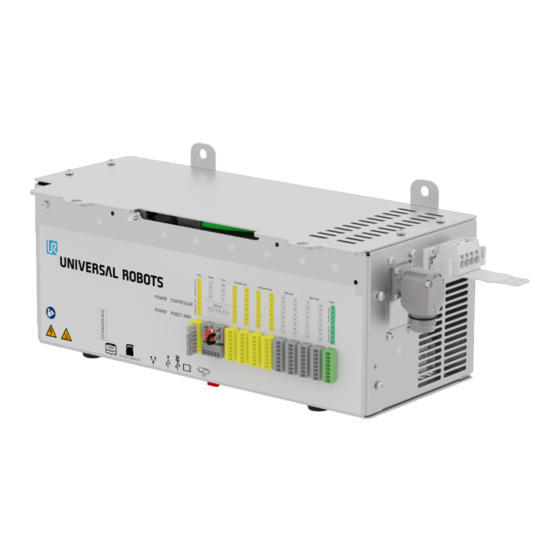
- Page 1 Installation Guide OEM Control Box Original instructions (en) Compatible robots: UR3e, UR5e, UR10e, UR16e, UR20, UR30...
- Page 3 Software Version: 5.16 Document Version:...
- Page 4 The information contained herein is the property of Universal Robots A/S and shall not be reproduced in whole or in part without prior written approval of Universal Robots A/S. The information herein is subject to change without notice and should not be construed as a commitment by Universal Robots A/S.
-
Page 5: Table Of Contents
Contents 1. Introduction 1.1. About this Document 1.2. What the Box Contains 1.3. Company Details 2. Cleaning Your Robot 2.1. Everyday Cleaning 2.2. Additional Cleaning 3. Safety 3.1. Safety Message Types 3.2. General Safety Precautions 4. Electrical Installation: AC variant 4.1. Required Items 4.2. How to Connect Wires to the Connector 4.3. - Page 6 7.4. How to Use Remote Control and Local Control 7.4.1. To Enable Remote Control 7.5. Remote ON/OFF Control and Emergency Stop 7.6. Connecting the ON/OFF control 7.7. Connecting the Remote Emergency Stop 8. OEM Control Box Specifications 8.1. Technical Specifications 8.2. Electrical Specifications 8.3.
-
Page 7: Introduction
1.1. About this Document This guide describes how to install an Universal Robots OEM Control Box with the following Universal Robots robot arm sizes: UR3e, UR5e, UR10e, UR16e, UR20 and UR30. Installation for both the AC variant and the DC variant are described. NOTICE Universal Robots disclaims any liability, even if all guidelines in this document are... -
Page 8: Cleaning Your Robot
2. Cleaning Your Robot 2.1. Everyday Cleaning You can wipe away any dust/dirt/oil observed on the robot arm and/or Teach Pendant using a cloth and one of the following cleaning agents: Water, 70% Isopropyl alcohol, 10% Ethanol alcohol or 10% Naphtha. In rare cases, very small amounts of grease can be visible from the joint. This does not affect the function, use, or lifetime of the joint. -
Page 9: Safety
3. Safety 3.1. Safety Message Types Safety messages are used to emphasize important information. Read all the messages to help ensure safety and to prevent injury to personnel and product damage. The safety message types are defined below. WARNING Indicates a hazardous situation that, if not avoided, can result in death or serious injury. -
Page 10: General Safety Precautions
3.2. General Safety Precautions Read the general safety messages below before installing, or operating the OEM Control Box. For more information on safety, refer to the Safety chapter in the Universal Robots User Manual. WARNING Failure to verify and validate safeguarding and functionality can result in death or serious injury. - Page 11 NOTICE Electrostatic Discharge (ESD) can damage sensitive components in the OEM Control Box. • Always wear an ESD wrist strap when working with the OEM Control Box electrical interfaces. Installation Guide OEM Control Box...
-
Page 12: Electrical Installation: Ac Variant
4. Electrical Installation: AC variant This section describes how to connect the OEM Control Box to an AC power source. WARNING: ELECTRICITY Performing installation or maintenance of equipment connected to a power source can lead to electric shock. • Ensure the equipment is disconnected from the power source before performing installation or maintenance. -
Page 13: How To Connect Wires To The Connector
4.2. How to Connect Wires to the Connector This section describes how to connect wires to a connector with locking levers: 1. Insert the screwdriver into a flat slot next to a connector hole. 2. Push the screwdriver until the clamp inside the hole opens. Keep the screwdriver in the slot, as shown. -
Page 14: Robot Connection
• Do not connect wires to poles without labels. 4.4. Robot Connection The robot arm connector, illustrated below, is next to the power supply connector. For details on connecting the robot arm cable, refer to the Universal Robots User Manual. Robot arm connector OEM CB connector Robot arm connector (e-Series) OEM CB connector (e-Series) -
Page 15: Circuit Breaker Installation
4.5. Circuit Breaker Installation Use a double pole circuit breaker to protect the power input connector, as it can also be used as a switch. If a fuse is used, then a two-pole switch must be installed between the fuse and power input connector. -
Page 16: Electrical Installation: Dc Variant
5. Electrical Installation: DC variant This section describes how to connect the OEM Control Box to a DC power source. WARNING: ELECTRICITY Performing installation or maintenance of equipment connected to a power source can lead to electric shock. • Ensure the equipment is disconnected from the power source before performing installation or maintenance. -
Page 17: How To Connect Wires To The Connector
5.2. How to Connect Wires to the Connector This section describes how to connect wires to a connector with locking levers: 1. Insert the screwdriver into a flat slot next to a connector hole. 2. Push the screwdriver until the clamp inside the hole opens. Keep the screwdriver in the slot, as shown. -
Page 18: Soft Start Circuit
To connect the OEM Control Box to the power source: 1. Connect the following wires to the connector: Neutral, Line and Ground (if supported). 2. Connect the ground wire to the facility ground if the application supports such connection. Connect the negative, and positive wires to the DC source. Ensure that the polarity is correct. 3. -
Page 19: Robot Connection
5.4. Robot Connection The robot arm connector, illustrated below, is next to the power supply connector. For details on connecting the robot arm cable, refer to the Universal Robots User Manual. Robot arm connector OEM CB connector Robot arm connector (e-Series) OEM CB connector (e-Series) - Page 20 The following illustration shows the circuit breaker wiring scheme. OEM power input Circuit breaker CAUTION Failure to install appropriate fuses or circuit breakers can result in equipment damage or personnel injury. • The installation shall comply with the standard IEC 60364. OEM Control Box Installation Guide...
-
Page 21: Mechanical Installation
6. Mechanical Installation 6.1. Working environment guidelines Follow these guidelines to ensure reliable operation of the OEM Control Box: • Keep free from dust and dirt. • Keep away from water, solvents, and chemicals. • Keep ambient air temperatures flowing into the OEM Control Box within 0–50°C. •... -
Page 22: Grounding
Ensure there is enough space for cables and sufficient air circulation around the Control Box. A minimum of 50 mm space around the air intake and outlets is recommended, and consideration should be made to avoid re-circulating air. For more information about the heat dissipation, see 8.3 Control Unit Heat Dissipation on page 27. -
Page 23: Connecting External Devices
7. Connecting External Devices 7.1. External Device Connection Ports The bottom side of the OEM Control Box contains a bracket with ports for connecting external devices. The following illustration shows the bracket. Teach Pendant port SD card slot Ethernet port USB ports Mini Displayport 10 A mini blade fuse The following table describes the ports. -
Page 24: How To Connect A Teach Pendant
7.3. How to Connect a Teach Pendant 7.3.1. To connect a Teach Pendant NOTICE Excessive strain at the port on the OEM Control Box can cause damage to the Teach Pendant connector and affect the functionality of the Teach Pendant. • Avoid pulling and/or exerting lateral forces on the Teach Pendant cable during installation. -
Page 25: How To Use Remote Control And Local Control
7.4. How to Use Remote Control and Local Control 7.4.1. To Enable Remote Control 1. On PolyScope, in the Header, tap the Hamburger Menu. 2. Select Settings, tap System and select Remote Control. 3. On the Remote Control screen, select Enable to activate Remote Control. To activate Local Control, in the Header, tap the Remote Control icon and select Local Control. - Page 26 The following illustration shows the minimum required Emergency Stop installation. For complete, in depth information about the electrical configurations, see the Electrical Interface in the UR User Manual available for download at: myur.universal-robots.com/manuals OEM Control Box Installation Guide...
-
Page 27: Oem Control Box Specifications
Typical Unit Input Voltage 24 - 48 Stand-by Power <7 External fuse Inrush current (200) 8.3. Control Unit Heat Dissipation Robot Type Max. Heat Dissipation UR20 350 W UR16e & UR10e 130 W UR5e & UR3e 100 W Installation Guide OEM Control Box... -
Page 28: Dimensional Drawings [Mm]
8.4. Dimensional drawings [mm] OEM Control Box Installation Guide... -
Page 29: Troubleshooting
9. Troubleshooting 9.1. OEM Control Box AC variant Symptom Possible Solution Check that the power source is wired correctly (see 4.3 Power Control Box does not turn on. Source Wiring: AC on page 13). Control Box turns on for a few Pressing the Power ON button for more than 5 seconds shuts the seconds then shuts down. -
Page 30: Cable Strain Relief Bracket
10. Cable Strain Relief Bracket The bracket provides cable strain relief when the Teach Pendant is in use, under normal operation. 10.1. OEM Control Box AC To install and use the cable strain relief bracket 1. Remove grommet 2. Remove screw 3. Clean area with alcohol solution and allow the 4. Remove protective film from adhesive patch alcohol to evaporate. -
Page 31: Oem Control Box Dc
7. Connect TP cable 8. Secure the TP cable with the included zip ties 10.2. OEM Control Box DC To install and use the cable strain relief bracket 2. Clean area with alcohol solution and allow the 1. Remove grommet alcohol to evaporate. 3. Remove protective film from adhesive patch 4. Align the bracket using the screw hole Installation Guide OEM Control Box... - Page 32 5. Connect TP cable 6. Secure the TP cable with the included zip ties OEM Control Box Installation Guide...
-
Page 33: Certifications
11. Certifications This section contains information about certificates and declarations valid for Universal Robots robots with OEM controllers. 11.1. Shipping materials As stated by our suppliers, Universal Robots robots shipping materials comply with the ISPM-15 requirements for producing wood packaging material and are marked accordingly. 11.2. - Page 34 8=UR20, 9=UR30 series Sequential numbering, restarting at 0 each year Universal Robots UR20 & UR30 with an OEM control box shall only be put into service upon being integrated into a final complete Incorporation machine (robot application or robot cell), which conforms with the provisions of the Machinery Directive and other applicable Directives.
- Page 35 Installation Guide OEM Control Box...
- Page 36 UR3e OEM DC, UR5e OEM DC, UR10e OEM DC, UR16e OEM DC Starting 20215000000 and higher Serial Number year 3 = UR3e, 5 = UR5e, 0 = UR10e (10kg payload), 2 = UR10e (12.5kg e-Series payload), 6 = UR16e Sequential numbering, restarting at 0 each year...
- Page 37 Installation Guide OEM Control Box...
- Page 38 China RoHS OEM Control Box Installation Guide...
- Page 39 OEM Control Box Installation Guide...
- Page 40 Software Name: PolyScope Software Version: 5.16 Document Version:...
Need help?
Do you have a question about the UR3e and is the answer not in the manual?
Questions and answers