Table of Contents
Advertisement
INSTRUCTION MANUAL
Please read carefully
before using the ma-
chine.
Keep for future reference.
This instruction manual/assembly in-
struction is to be considered as part of
the machine. Suppliers of new and sec-
ond-hand machines are required to
document in writing that the instruc-
tion manual/assembly instruction was
Original instructions
delivered with the machine and hand-
d
ed over to the customer.
5902662-
-en-0418
Advertisement
Table of Contents

Subscribe to Our Youtube Channel
Related Manuals for Rauch QUANTRON-A AXIS-M 20 Q


Summary of Contents for Rauch QUANTRON-A AXIS-M 20 Q
- Page 1 INSTRUCTION MANUAL Please read carefully before using the ma- chine. Keep for future reference. This instruction manual/assembly in- struction is to be considered as part of the machine. Suppliers of new and sec- ond-hand machines are required to document in writing that the instruc- tion manual/assembly instruction was Original instructions delivered with the machine and hand-...
-
Page 2: Technical Improvements
This constitutes no obligation to make such improvements or changes on machines that have already been sold. We will be pleased to answer any other questions that you might have. Yours sincerely RAUCH Landmaschinenfabrik GmbH... -
Page 3: Table Of Contents
Table of Contents Preface Technical improvements User instructions About this operator's manual ......... . . 1 Presentation information . - Page 4 Table of Contents Operation QUANTRON-A Control unit activation..........29 Menu navigation .
- Page 5 Table of Contents Spreading operation with the QUANTRON-A control unit TELIMAT ............87 Working with sections (AXIS only).
- Page 6 Table of Contents...
-
Page 7: User Instructions
User instructions User instructions About this operator's manual This operator's manual is an integral part of the control unit QUANTRON-A. The operator's manual contains important instructions for safe, proper and eco- nomic use and maintenance of the control unit. Compliance with it helps to avoid danger, reduce maintenance costs and downtime and to increase the ma- chine's reliability and service life. - Page 8 User instructions Warning severity level The degree of danger is indicated by the signal word. The levels are classified as follows: n DANGER Type and source of danger This warning warns of a danger posing an immediate threat to the health and life of persons.
-
Page 9: Instructions And Procedures
User instructions 1.2.2 Instructions and procedures Steps that the operator must carry out are shown as a numbered list. 1. Instruction for action step 1 2. Instruction for action step 2 Instructions involving only one step are not numbered. The same applies for ac- tion steps that do not have a specific sequence. - Page 10 User instructions...
-
Page 11: Layout And Function
Layout and function Layout and function Overview of supported versions NOTICE Some models are not available in all countries. 2.1.1 Function/options Spreading depending on forward speed MDS 10.1 Q MDS 11.1 Q MDS 12.1 Q MDS 17.1 Q ... -
Page 12: Layout Of The Control Unit - Overview
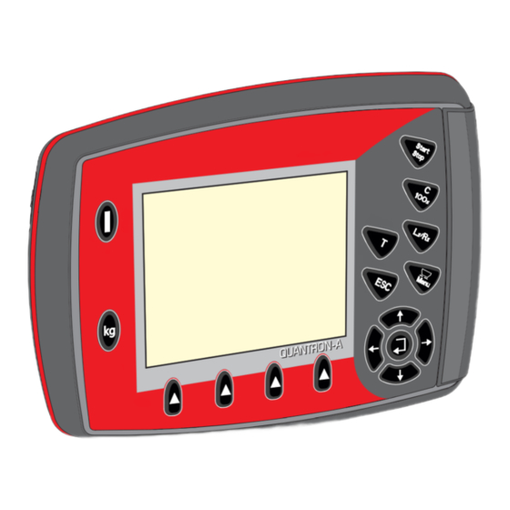
Layout and function Layout of the control unit - overview Figure 2.1: Control unit QUANTRON-A No. Designation Function Control panel Consisting of foil buttons used to operate the device and the display for operating screens. Machine cable plug 39-pin plug connector for connecting the machine connector cable to sensors and actuating cylinders. -
Page 13: Control Elements
Layout and function Control elements The unit is operated by means of 17 foil buttons (13 fixed and 4 freely configur- able foil buttons). Figure 2.2: Control panel at the front of the unit NOTICE The operating manual describes the control unit functions QUANTRON-A as of software version 3.10.00. - Page 14 Layout and function Designation Function Preselected section Toggle key for alternating between 4 states. setting Pre-selection of sections for changing the quan- tity. Page 61 Left Right or Left + Right AXIS only: Section management (VariSpread function) Page 13 Menu Switch between operating screen and main menu.
-
Page 15: Display
Layout and function Display The display shows the current status information and the selection and input op- tions for the control unit. The most important information concerning the operation of the fertiliser spreader is displayed on the operating screen. 2.4.1 Operating screen description NOTICE The exact representation of the operating screen depends on the actual settings... - Page 16 Layout and function Figure 2.5: Control unit display (example MDS operating screen)
- Page 17 Layout and function The icons and displays in the example have the following meaning: No. Icon/display Meaning (in the example shown) Metering slide Current opening position of the left metering slide. scale opening left Operating mode Shows the current operating mode. TELIMAT icon This icon appears on the right for AXIS and on the left for MDS if the TELIMAT sensors are installed and...
-
Page 18: Display Of The Metering Slide Status
Layout and function 2.4.2 Display of the metering slide status Figure 2.6: AXIS metering slide status display Figure 2.7: MDS metering slide status display [A] Spreading operation inactive (STOP) [1] Section deactivated [2] Section activated [B] Machine in spreading operation (START) [3] Section deactivated [4] Section activated... -
Page 19: Section Width Display (Axis Only)
Layout and function 2.4.3 Section width display (AXIS only) Figure 2.8: Display of the section status (example with VariSpread 8) [1] Activated sections with 4 possible spreading width steps [2] The leftsection is reduced by 2 section steps Further display and setting options are explained in chapter 5.2: Working with sections (AXIS only), page... -
Page 20: Library Of Symbols Used
Layout and function Library of symbols used The screen of the QUANTRON-A control unit displays symbols for menus and functions. Symbol Meaning Quantity adjustment + (plus) Quantity adjustment - (minus) Quantity adjustment, left + (plus) Quantity adjustment, left - (minus) Quantity adjustment, right + (plus) Quantity adjustment, right - (minus) Manual change of the metering slide position + (plus) - Page 21 Layout and function Symbol Meaning Reduce section, right (minus) Increase right section (plus) Reduce section, left (minus) Increase left section (plus)
-
Page 22: Structural Overview Of Easy Mode Menu
Layout and function Structural overview of Easy Mode menu Setting the mode is described in section 4.10.3: Mode, page... -
Page 23: Structural Overview Of Expert Mode Menu
Layout and function Structural overview of Expert Mode menu Setting the mode is described in section 4.10.3: Mode, page... - Page 24 Layout and function...
-
Page 25: Attachment And Installation
Attachment and installation Attachment and installation Requirements for the tractor Before installing the control unit, check to make sure your tractor meets the fol- lowing requirements: A minimum voltage of 11 V is essential at all times, even if multiple loads are ... -
Page 26: 7-Pin Plug Connector
Attachment and installation 3.2.2 7-pin plug connector The control unit receives the pulses for the current forward speed via the 7-pin plug connector 9684-1/ISO 11786). For this purpose, the 7-pin to 8-pin cable (ac- cessory) is connected to the forward speed sensor at the plug connector. [1] PIN 1: actual forward speed (radar) [2] PIN 2: theoretical forward speed (e. -
Page 27: Connecting The Control Unit
Attachment and installation Connecting the control unit NOTICE After the control unit has been switched on, QUANTRON-A the display shows the machine number for a short time. NOTICE Note the machine number The control unit QUANTRON-A is factory-calibrated for the fertiliser spreader with which it has been delivered. -
Page 28: Mds And Axis-M
Attachment and installation 3.3.1 MDS and AXIS-M Standard schematic connection diagram: km/h Figure 3.3: Standard schematic connection diagram QUANTRON-A [1] Serial interface RS232, 8-pin plug connector [2] 39-pin machine plug [3] Metering slide actuator left/right [4] Option (level sensor left/right) [5] Option (TELIMAT sensor top/bottom) [6] Battery [7] 3-pin plug connector conforming to DIN 9680 / ISO 12369... - Page 29 Attachment and installation Schematic connection diagram for wheel sensor: km/h Figure 3.4: Schematic connection diagram QUANTRON-A (wheel sensor) [1] Serial interface RS232, 8-pin plug connector [2] 39-pin machine plug [3] Metering slide actuator left/right [4] Option (level sensor left/right) [5] Option (TELIMAT sensor top/bottom) [6] Battery [7] 3-pin plug connector conforming to DIN 9680 / ISO 12369 [8] Option: Y-cable (V24 RS232 interface for storage medium)
- Page 30 Attachment and installation Schematic connection diagram: Power supply via ignition lock km/h km/h Figure 3.5: Schematic connection diagram QUANTRON-A (power supply via ignition lock) [1] Serial interface RS232, 8-pin plug connector [2] 39-pin machine plug [3] Metering slide actuator left/right [4] Option (level sensor left/right) [5] Option (TELIMAT sensor top/bottom) [6] Battery...
-
Page 31: Axis-M Emc
Attachment and installation 3.3.2 AXIS-M EMC Standard schematic connection diagram: Figure 3.6: Schematic connection diagram QUANTRON-A [1] Serial interface RS232, 8-pin plug connector [2] 39-pin machine plug [3] Option: Drop point adjustment (machines with VariSpread) [4] M EMC sensors (left, right, centre) [5] Option: TELIMAT sensor top/bottom [6] Option: Filling level sensor left/right [7] Metering slide actuator left/right... - Page 32 Attachment and installation Schematic connection diagram for wheel sensor: km/h Figure 3.7: Schematic connection diagram QUANTRON-A [1] Serial interface RS232, 8-pin plug connector [2] 39-pin machine plug [3] Option: Drop point adjustment (machines with VariSpread) [4] M EMC sensors (left, right, centre) [5] Option: TELIMAT sensor top/bottom [6] Option: Filling level sensor left/right [7] Metering slide actuator left/right...
- Page 33 Attachment and installation Schematic connection diagram: Power supply via ignition lock km/h km/h Figure 3.8: Schematic connection diagram QUANTRON-A [1] Serial interface RS232, 8-pin plug connector [2] 39-pin machine plug [3] Option: Drop point adjustment (machines with VariSpread) [4] M EMC sensors (left, right, centre) [5] Option: TELIMAT sensor top/bottom [6] Option: Filling level sensor left/right [7] Metering slide actuator left/right...
-
Page 34: Metering Slide Preparation
Attachment and installation Metering slide preparation The fertiliser spreaders AXIS Q, AXIS-M EMC and MDS Q are fitted with an elec- tronic metering slide actuator for setting the spreading volume. n CAUTION Check the position of the metering slides on the AXIS fertil- iser spreader The actuators being operated by the QUANTRON-A can cause damage to the machine’s metering slides if the stop levers are... -
Page 35: Operation Quantron-A
Operation QUANTRON-A Operation QUANTRON-A n CAUTION Risk of injury due to ejected fertiliser In the case of a fault, it is possible that the metering slide will open unexpectedly during road transportation to the spreading location. There is a risk of slipping and personal injury due to ejected fertil- iser. - Page 36 Operation QUANTRON-A Activation: 1. Press the ON/OFF switch [1]. After a few seconds, the control unit start-up screen appears. Shortly after, the control unit will display the activation menu for a few seconds. 2. Press the Enter key. ...
-
Page 37: Menu Navigation
Operation QUANTRON-A Menu navigation NOTICE Important notes regarding the display and navigation between menus are pro- vided in chapter 1.2.5: Menu hierarchy, keys and navigation, page Accessing the main menu Press the Menu key. See 2.3: Control elements, page ... -
Page 38: Weighing Trip Counter
Operation QUANTRON-A Weighing trip counter This menu provides values regarding the spreading work carried out as well as functions for weighing operation. Press the kg key on the control unit. The Weighing/Trip counter menu is displayed. Figure 4.2: Weighing/Trip count menu Sub-menu Meaning... -
Page 39: Trip Counter
Operation QUANTRON-A 4.3.1 Trip counter This menu provides the following values: spread quantity (kg) spread area (ha) spread distance (m) Figure 4.3: Trip counter menu [1] Display showing spread quantity since the last reset [2] Display showing spread area since the last reset [3] Display showing spread distance since the last reset [4] Clearing the trip counter: all values to 0 Clearing the trip counter:... -
Page 40: Displaying The Remaining Quantity
Operation QUANTRON-A 4.3.2 Displaying the remaining quantity In the Rest (kg, ha, m) menu, you can request or input the residual quantity within the hopper. The menu shows the possible area (ha) and distance (m) which can still be spread using the remaining fertiliser quantity. Both displays are calculated based on the following values: Fertiliser settings, ... -
Page 41: Zeroing The Scales (Axis With Weigh Cells Only)
Operation QUANTRON-A Entering the residual quantity when refilling: 1. Open the Weighing trip counter > Rest (kg, ha, m) menu. The residual quantity from the last spreading process is displayed. 2. Fill the hopper. 3. Enter the new total weight for the fertiliser in the hopper. Also see chapter 4.13.2: Entering values with the cursor keys, page 4. -
Page 42: Main Menu
Operation QUANTRON-A Main menu Figure 4.5: Main menu QUANTRON-A The main menu displays the following sub-menus. Sub-menu Meaning Description Fertiliser settings Fertiliser and spreader operation set- Page 39 tings. Machine Settings Tractor and fertiliser spreader settings. Page 54 Fast emptying Direct access to the menu for fast fertil- Page 63 iser spreader emptying. -
Page 43: Fertiliser Settings In Easy Mode
Operation QUANTRON-A Fertiliser settings in easy mode The mode settings are described in section 4.10.3: Mode, page In this menu, the fertiliser and spreading operation settings can be changed. Open the Main menu > Fertiliser settings menu. NOTICE For the M EMC function, the mode is automatically set to Expert NOTICE The Fertiliser settings menu is different for the AXIS and MDS fertiliser spreader. - Page 44 Operation QUANTRON-A Sub-menu Meaning/possible values Description Fertiliser name Selected fertiliser. Appl. rate (kg/ha) Target value entry for the application rate Page 42 in kg/ha. Working width (m) Determination of the working width to be Page 42 spread. Flow factor Entering the flow factor of the fertiliser Page 43 used Drop point...
-
Page 45: Fertiliser Settings In Expert Mode
Operation QUANTRON-A Fertiliser settings in Expert mode The mode settings are described in section 4.10.3: Mode, page 73 NOTICE For the M EMC function, the mode is automatically set to Expert In this menu, the fertiliser and spreading operation settings can be changed. As opposed to in Easy mode, this menu contains further setting pages as well as the fertiliser chart. - Page 46 Operation QUANTRON-A Figure 4.10: Fertiliser settings menu, page 3 (AXIS/MDS) The main menu displays the following sub-menus. Sub-menu Meaning/possible values Description Fertiliser name Fertiliser selected from the fertiliser chart. Page 52 Appl. rate (kg/ha) Target value entry for the application rate Page 42 in kg/ha.
- Page 47 Operation QUANTRON-A Sub-menu Meaning/possible values Description Factory setting: 540 rpm Page 49 Bound. srd. type Selection list: Selection with Arrow keys Boundary Confirmation Border with the Enter TELIMAT bor- Saving the TELIMAT settings for bounda- For fertiliser der/boundary ry fertilisation.
-
Page 48: Application Rate
Operation QUANTRON-A 4.6.1 Application rate In this menu, you can enter the desired target value for the application rate. Entering the application rate: 1. Open the Fertiliser settings > Appl. rate (kg/ha) menu. The currently applied application rate is displayed. 2. -
Page 49: Flow Factor
Operation QUANTRON-A 4.6.3 Flow factor The flow factor ranges between 0.2 and 1.9. The following applies for consistant basic settings (km/h/, working width, kg/ha): If the flow factor is increased, the application rate is decreased. If the flow factor is decreased, the application rate is increased. ... - Page 50 Operation QUANTRON-A Minimum factor In accordance with the entered flow factor value, the machine control unit auto- matically sets the minimum factor to one of the following values: The minimum factor is 0.2 if the input value is smaller than 0.5. ...
-
Page 51: Drop Point
Operation QUANTRON-A 4.6.4 Drop point NOTICE Entering the drop point with the Q M-AXIS is merely informative and does not affect the settings of the fertiliser spreader. In this menu, you can enter the drop point for information purposes. 1. Open the Fertiliser settings > Drop point menu. 2. -
Page 52: Calibration
Operation QUANTRON-A 4.6.6 Calibration NOTICE The Calibration menu is locked for the M EMC function and in the AUTO km/h + AUTO kg operating mode. This menu item is inactive. In this menu, you can determine the flow factor based on a calibration and save it in the control unit. - Page 53 Operation QUANTRON-A Selecting the section: 5. Set the spreader side on which the calibration is to be carried out. Press the F1 function key to select left spreading side. Press the F4 function key to select right spreading side. ...
- Page 54 Operation QUANTRON-A Recalculating the flow factor n WARNING Risk of injury due to rotating machine parts Contact with rotating machine components (universal drive shaft, hubs) may cause bruises, abrasions and crushing injuries. Body parts or objects may be caught or drawn in. ...
-
Page 55: Spreading Disc Type
Operation QUANTRON-A 4.6.7 Spreading disc type NOTICE For optimal idle measurement check the correct entries are in the Fertiliser settings menu. The entries in the Spreading disc and PTO shaft menu items must comply with the actual settings of your machine. The mounted spreading disc type is preset in the control unit at the factory. -
Page 56: Calculate Optipoint (Axis Only)
Operation QUANTRON-A 4.6.9 Calculate OptiPoint (AXIS only) In the Calculate OptiPoint menu, you can enter the parameters to calculate the optimum switch-on and switch-off distances in the headlands. It is very important to enter the distance factor of the fertiliser used to obtain an exact calculation. -
Page 57: Gps Control Information
Operation QUANTRON-A NOTICE On this page, you can manually adjust the parameters. See chapter 5.7: GPS Control, page Changing the values 6. Highlight the selected input. 7. Press the Enter key. 8. Enter the new values. 9. Press the Enter key. 10. -
Page 58: Fertiliser Chart
Operation QUANTRON-A 4.6.11 Fertiliser chart In these menus, you can create and manage your own fertiliser charts. NOTICE The selection of a fertiliser chart has an effect on the fertiliser settings, the con- trol unit and the mineral fertiliser spreader. The set application rate is overwrit- ten by the stored value from the fertiliser chart. - Page 59 Operation QUANTRON-A Selecting a fertiliser chart: 1. Open the Fertiliser settings > Fertiliser chart menu. 2. Select the required fertiliser chart. 3. Press the Enter key. The selection window is displayed. 4. Highlight the Open element... option. 5. Press the Enter key. ...
-
Page 60: Machine Settings
Operation QUANTRON-A Machine settings NOTICE The Machine menu. The Fertiliser settings menu is different for the fertiliser spreader AXIS and MDS. In this menu, the tractor and machine settings can be configured. Open the Machine settings menu. Figure 4.14: Machine settings menu (example) Sub-menu Meaning Description... -
Page 61: Forward Speed Calibration
Operation QUANTRON-A 4.7.1 Forward speed calibration The forward speed calibration is the basic requirement for an exact spreading re- sult. Factors such as tyre size, a different tractor, four-wheel drive, slippage be- tween tyres and ground, ground characteristics and tyre pressure influence the speed measurement and, therefore, the spreading result. - Page 62 Operation QUANTRON-A New calibration of the forward speed signal: You can either overwrite an existing profile or create a profile in an empty memory location. 1. Select the desired memory location in the Tractor calibration menu using the function key below. 2.
- Page 63 Operation QUANTRON-A The number of pulses of the speed signal must still be specified below. If the ex- act pulse count is known, it can be entered directly: 8. Call up the Tractor (km/h) > New calibration > Imp/100m menu item. ...
-
Page 64: Auto/Man Mode
Operation QUANTRON-A 4.7.2 AUTO/MAN mode The default operating mode is AUTO. The control unit automatically controls the actuators based on the speed signal. The manual mode is only applied in the following cases: there is no speed signal (radar or wheel sensor not available or defective), ... - Page 65 Operation QUANTRON-A AUTO km/h: Automatic operation NOTICE In order to achieve an optimum spreading result, a calibration test should be car- ried out before spreading. 1. Switch on the QUANTRON-A control unit. 2. Open the Machine settings > AUTO/MAN mode menu. 3.
- Page 66 Operation QUANTRON-A MAN scale: manual operation with scale value 1. Open the Machine settings > AUTO/MAN mode menu. 2. Select MAN scale in the menu. The display shows the metering slide opening menu. 3. Enter the scale value for the metering slider opening. 4.
-
Page 67: Quantity
Operation QUANTRON-A 4.7.3 +/- Quantity In this menu, an Application rate adjustment percentage for standard spread- ing can be specified. The preset value of the metering slider opening serves as basis (100%). NOTICE During operation, you can use the F2/F3 function keys to change the application rate by the factor of +/- quantity at any time. -
Page 68: Easy Toggle (Axis Only)
Operation QUANTRON-A 4.7.5 Easy Toggle (AXIS only) Here, you can limit the toggle function of the L%/R % key to 2 conditions of the F1 to F4 function keys. By doing so, you can avoid unnecessary toggling action in the operating screen. 1. -
Page 69: Fast Emptying
Operation QUANTRON-A Fast emptying To clean the machine after spreading or to quickly empty residual spreading ma- terial, select the Fast emptying menu. Before storing the machine, it is recommended that you also completely open the metering slides using the fast emptying function and to switch off the QUANTRON- A in this state. - Page 70 Operation QUANTRON-A 2. Press the Function key to select the section for which the fast emptying func- tion is to be carried out. The selected section is shown as an icon in the display. 3. Press the Start/Stop key. ...
-
Page 71: Field Data
Operation QUANTRON-A Field data In this menu, you can create and manage up to 200 field datas. Open the Main menu > Field data menu. Figure 4.20: Field data menu [1] Page number display [2] Display of filled field data [3] Display of active field data [4] Name of field data [5] F4 function key: no function... -
Page 72: Starting The Recording
Operation QUANTRON-A 4.9.2 Starting the recording Figure 4.21: Display of current field data [1] Display of the page number [2] Name field of field data [3] Value fields [4] Display of the start time/date [5] Display of the stop time/date [6] Name field of fertiliser [7] Name field of fertiliser manufacturer [8] Function key Start... - Page 73 Operation QUANTRON-A 3. Press the F1 function key under the start icon. The recording starts. The Field data menu displays the recording icon for the current field da- The operating screen displays the recording symbol. NOTICE If a different field data file is opened, the current field data file is stopped. The active field data file cannot be deleted.
-
Page 74: Stopping The Recording
Operation QUANTRON-A 4.9.3 Stopping the recording 1. Open the 1st page of the active field data in the Field data menu. 2. Press the F2 function key below the stop symbol. The recording is stopped. 4.9.4 Deleting field data The control unit QUANTRON-A facilitates the deletion of recorded field data. -
Page 75: System/Test
Operation QUANTRON-A 4.10 System/test Use this menu for the system and test settings of the control unit. Open the Main menu > System / Test menu. Figure 4.23: System/Test menu Sub-menu Meaning Description Brightness Display settings The settings can be adjust- ed with the function keys + or -. - Page 76 Operation QUANTRON-A Sub-menu Meaning Description Date Setting the current date. Selection and modification of the settings by means of the Arrow keys; confirma- tion using the Enter key Time Setting the current time. Selection and modification of the settings by means of the Arrow keys;...
-
Page 77: Setting The Language
Operation QUANTRON-A 4.10.1 Setting the language In the QUANTRON-A control unit, several languages can be set. The language package for your country is pre-set at the factory. 1. Open the System/Test > Language menu. The display shows the first of four pages. Figure 4.24: Language sub-menu, page 1 2. -
Page 78: Display Configuration
Operation QUANTRON-A 4.10.2 Display configuration The display fields in the operating screen of the control unit can be configured as desired. You can assign the three display fields with the following values if de- sired: Forward speed Flow factor (FF) ... -
Page 79: Mode
Operation QUANTRON-A 4.10.3 Mode In the QUANTRON-A control unit, 2 different modes are possible: The Easy mode or the Expert mode. NOTICE For the M EMC function, the mode is automatically set to Expert In the Easy mode, only the parameters of the fertiliser settings required for ... -
Page 80: Test/Diagnosis
Operation QUANTRON-A 4.10.4 Test/diagnosis The Test/diagnosis menu enables function monitoring and checking of specific sensors/actuators. NOTICE This menu is for information purposes only. The list of sensors depends on the equipment of the machine. Sub-menu Meaning Description Slide test points Test for approaching the various posi- Checking the cali- tion points of the sliders. - Page 81 Operation QUANTRON-A Example metering slide n CAUTION Risk of injury due to moving machine parts. During the tests, machine parts may start to move automatically. Before carrying out the test, ensure that nobody is present in the danger zone of the machine. 1.
- Page 82 Operation QUANTRON-A LIN bus example 1. Open the System / Test > Test/diagnosis menu. 2. Highlight the Linbus menu item. 3. Press the Enter key. The actuator/sensor status is displayed. Figure 4.27: Test/diagnosis, example: Linbus [1] Status display [2] Start self-test [3] Connected actuators LIN bus participant status notification The actuators are in different states:...
-
Page 83: Data Transmission
Operation QUANTRON-A 4.10.5 Data transmission Data transmission is carried out using various data protocols. Sub-menu Meaning Automatic field documentation; transmission of field data to a PDA and/or Pocket PC via Bluetooth LH5000 Serial communication e.g. spreading using application cards GPS Control Protocol for the automatic section control with an external ter- minal VRA GPS con-... -
Page 84: Total Data Counter
Operation QUANTRON-A 4.10.6 Total data counter In this menu, all of the spreader's counter readings are displayed. spread quantity in kg spread area in ha spread time in h distance travelled in km NOTICE This menu is for information purposes only. -
Page 85: Change Unit System
Operation QUANTRON-A 4.10.7 Change unit system The system of units has been preset at the factory. However, the system can be changed from metric to imperial units at any time. 1. Open System/test menu. 2. Select the Unit menu. 3. Press the enter key to switch between imperial and metric. ... -
Page 86: Hopper Cover (Axis Only, Optional Equipment)
Operation QUANTRON-A 4.12 Hopper cover (AXIS only, optional equipment) n WARNING Danger of crushing and shearing due to components operat- ed by an external force The hopper cover will move without warning and can cause per- sonal injury. Ensure that nobody is present in the hazard zone. The AXIS-H EMC machine is equipped with an electrically operated hopper cov- er. - Page 87 Operation QUANTRON-A n CAUTION Material damage due to insufficient clearance Opening and closing the hopper cover requires a sufficient clear- ance above the hopper. If the clearance is insufficient, the hopper cover may tear. The hopper cover lever may be damaged and the hopper cover may damage the environment.
-
Page 88: Special Functions
Operation QUANTRON-A 4.13 Special functions 4.13.1 Text input In some menus, freely editable text can be entered. Figure 4.29: Text input menu [1] Input field [2] Character field, display of available characters (language-dependent) [3] Function keys for navigation within the input field Entering text: 1. - Page 89 Operation QUANTRON-A Overwriting characters: A single character can be overwritten by another character. 1. Use the Function keys to move the cursor to the position of the character to be deleted first in the input field. 2. Use the arrow keys to select the character to be written in the character field. 3.
-
Page 90: Entering Values With The Cursor Keys
Operation QUANTRON-A 4.13.2 Entering values with the cursor keys In some menus, numerical values can be entered. Figure 4.30: Entering numerical value (example application rate) [1] Input field Precondition: You are already in the menu in which you can enter numerical values. 1. -
Page 91: Creating Screenshots
Operation QUANTRON-A 4.13.3 Creating screenshots With every software update, data will be overwritten. We recommend always stor- ing your settings as screenshots (screen copy) on a USB stick before implement- ing a software update. Use a USB stick with an illuminated status indicator (LED). ... - Page 92 Operation QUANTRON-A...
-
Page 93: Spreading Operation With The Quantron-A Control Unit
Spreading operation with the QUANTRON-A control unit Spreading operation with the QUANTRON-A control unit The control unit QUANTRON-A supports you in setting up your machine before you start your work. During spreading, control unit functions are also active in the background. -
Page 94: Working With Sections (Axis Only)
Spreading operation with the QUANTRON-A control unit Working with sections (AXIS only) 5.2.1 Spreading with reduced sections Spreading can be realized with sections on one or both sides to adapt the full spreading width to the field requirements. Each spreading side can be adjusted in 4 (VariSpread Dynamic) or 2 (VariSpread 4) steps. -
Page 95: Spreading Operation With One Section And In Boundary Spreading Mode
Spreading operation with the QUANTRON-A control unit 5.2.2 Spreading operation with one section and in boundary spreading mode During the spreading operation, the sections can be changed gradually and the limited border spreading can be activated. The figure below shows the operating screen with activated limited border spreading and activated sections. -
Page 96: Spreading With Automatic Operating Mode (Auto Km/H + Auto Kg)
Spreading operation with the QUANTRON-A control unit Spreading with automatic operating mode (AUTO km/h + AUTO kg) Mass flow control with the M EMC function Mass flow is measured separately on both spreading disc sides. Thus deviations to the specified application rate can be immediately corrected. The M EMC function requires the following machine data for mass flow control: PTO speed ... - Page 97 Spreading operation with the QUANTRON-A control unit 8. Press the Start/Stop key. The spreading starts. As long as the PTO shaft is operating, a new idle measurement will automatically start after the expiration of the idle time every 20 minutes. Under certain conditions, idle measurement is required to capture new reference data before you continue spreading.
-
Page 98: Spreading In The Auto Km/H Operating Mode
Spreading operation with the QUANTRON-A control unit Spreading in the AUTO km/h operating mode In AUTO km/h operating mode, the control unit automatically controls the actua- tor depending on the speed signal. 1. Configure the fertiliser settings: Application rate (kg/ha) ... -
Page 99: Spreading In The Man Km/H Operating Mode
Spreading operation with the QUANTRON-A control unit Spreading in the MAN km/h operating mode If there is no forward speed signal, the MAN km/h operating mode is active. 1. Switch on the QUANTRON-A control unit. 2. Open the Machine settings > AUTO/MAN mode menu. 3. -
Page 100: Spreading In The Man Scale Operating Mode
Spreading operation with the QUANTRON-A control unit Spreading in the MAN scale operating mode The MAN scale operating mode enables manual adjustment of the metering slide opening during the spreading operation. Precondition: The metering slides are open (activation with the Start/Stop key). ... -
Page 101: Gps Control
Spreading operation with the QUANTRON-A control unit GPS Control The QUANTRON-A control unit can be combined with GPS-compatible devices. Various data is exchanged between both devices to automate control. NOTICE We recommend using our QUANTRON-Guide control unit in combination with QUANTRON-A. - Page 102 Spreading operation with the QUANTRON-A control unit Switch-on distance (m) Switch-on distance refers to the switch-on distance (figure 5.6 [A]) relating to the field border (figure 5.6 [C]). At this position in the field, the metering slides start to open. This distance depends on the type of fertiliser and represents the ideal switch-on distance for optimised fertiliser distribution.
- Page 103 Spreading operation with the QUANTRON-A control unit Switch-off distance (m) Switch-off distance refers to the switch-off distance (figure 5.7 [B]) relating to the field border (figure 5.7 [C]). At this position in the field, the metering slides start to close. Figure 5.7: Switch-off distance (relating to field border) [B] Switch-off distance...
- Page 104 Spreading operation with the QUANTRON-A control unit...
-
Page 105: Alarm Messages And Possible Causes
Alarm messages and possible causes Alarm messages and possible causes Various alarm messages can be displayed on the control unit display. Alarm message meanings No. Message on display Meaning Possible cause Fault in dosing system. Stop! The metering system actuator cannot reach the target value. - Page 106 Alarm messages and possible causes No. Message on display Meaning Possible cause Transmission fault. No An error has occurred during data transmis- RS232 connection sion to the control unit. The data have not been transmitted. Error by setting TELIMAT. Alarm for the TELIMAT sensor.
- Page 107 Alarm messages and possible causes No. Message on display Meaning Possible cause The spreader ist set to re- The flow factor must lie within a range of duced disc speed. The idle 0.50 - 1.80. measurement cannot be The newly calculated or entered flow ...
-
Page 108: Clearing An Error/Alarm
Alarm messages and possible causes Clearing an error/alarm 6.2.1 Acknowledging an alarm message Alarm messages are highlighted on the display and displayed with a warning symbol. Figure 6.1: Alarm message (e.g. metering device) Acknowledging an alarm message: 1. Rectify the cause of the alarm message. See the operating manual for the fertiliser spreader and section 6.1: Alarm message meanings, page... -
Page 109: Special Equipment
Special equipment Special equipment No. Illustration Designation Level sensor for AXIS/MDS Forward speed sensor for QUANTRON-A Y cable RS232 for data exchange (e.g. GPS, N sensor, etc.) System tractor cable set for QUANTRON-A 12m AXIS... - Page 110 Special equipment No. Illustration Designation GPS cable and receiver TELIMAT sensor AXIS Universal holder for QUANTRON-A...
-
Page 111: Index
Index Index Fertiliser settings 29, 36 Application rate 42 Application rate 11, 42 Calibration 46–48 Composition 41 Fertilisation method 41 Brightness Fertiliser chart 41, 53 GPS control 41 Calibration Limited border spreading 41 46–48, 55 Manufacturer 41 Speed 46 Mounting height 41 Composition OptiPoint 41, 50 Connection... - Page 112 Index Language Operating mode 69, 71 AUTO km/h 59, 92 Late fertilising AUTO km/h + AUTO kg 58, 90 TELIMAT 41 MAN km/h 59, 93 Limited border spreading 41, 89 MAN scale 60, 94 Operating screen M EMC function 29, 43, 49, 58, 90 Operation 29–84 Idle measurement 90...
- Page 113 Index System/test 36, 69–72, 74 Brightness 69 Unit Data transmission 70 imperial 79 Date 70 metric 79 Display configuration 69 Language 69 Mode 69 Weighing trip counter Service 70 Test/diagnosis 69 Time 70 Zero the Total data counter 70 scales 32, 35 TELIMAT 11, 87 Sensor 104...
- Page 114 Index...
-
Page 115: Terms/Conditions Of Warranty
Warranty claims are rendered void if RAUCH original spare parts were not used. Therefore, the directions in the operating manual must be observed. In all cases of doubt contact our sales representatives or the factory directly.
Need help?
Do you have a question about the QUANTRON-A AXIS-M 20 Q and is the answer not in the manual?
Questions and answers