Icom IC-V8000 Instruction Manual
Vhf fm transceiver
Hide thumbs
Also See for IC-V8000:
- Instruction manual (88 pages) ,
- Service manual (35 pages) ,
- Optional instructions (12 pages)
Table of Contents
Advertisement
Quick Links
INSTRUCTION MANUAL
VHF FM TRANSCEIVER
iV8000
This device complies with Part 15 of the FCC rules. Operation is sub-
ject to the following two conditions: (1) This device may not cause
harmful interference, and (2) this device must accept any interference
received, including interference that may cause undesired operation.
Advertisement
Table of Contents

Subscribe to Our Youtube Channel
Related Manuals for Icom IC-V8000


Summary of Contents for Icom IC-V8000
- Page 1 INSTRUCTION MANUAL VHF FM TRANSCEIVER iV8000 This device complies with Part 15 of the FCC rules. Operation is sub- ject to the following two conditions: (1) This device may not cause harmful interference, and (2) this device must accept any interference received, including interference that may cause undesired operation.
-
Page 2: Explicit Definitions
We understand making you have a choice of many different the IC-V8000. radios in the market place. I want to take a couple of mo- ments of your time to thank you for making your IC-V8000 your radio of choice, and hope you agree with ICOM’s philos- EXPLICIT DEFINITIONS ophy of “technology first.”... - Page 3 DC power cable between the DC plug and fuse holder. If an incorrect connection is made after cutting, the Icom microphones only (supplied or optional). Other man- transceiver may be damaged. ufacturer’s microphones have different pin assignments and may damage the transceiver if attached.
-
Page 4: Panel Description
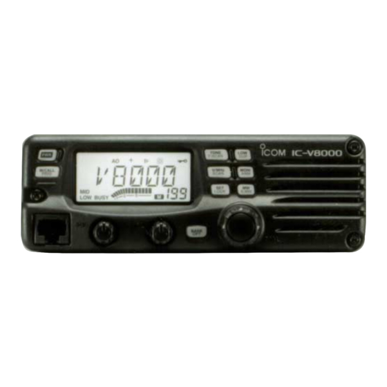
PANEL DESCRIPTION I Front panel Function display (p. 00) TONE T-SCAN V/MHz M/CALL MONI SCAN PRIO LOCK S.MW BANK Speaker q POWER SWITCH [PWR] e MICROPHONE CONNECTOR Turns power ON and OFF when pushed for 1 sec. Connects the supplied microphone. (p. 00) w MEMORY/CALL•PRIORITY SWITCH [M/CALL(PRIO)] r SQUELCH CONTROL [SQL] (p. - Page 5 PANEL DESCRIPTION y BANK•OPTION SWITCH [BANK(OPT)] !2 TONE/TONE SCAN SWITCH [TONE(T-SCAN)] ➥ Selects memory memory bank when pushed. (p. 00) ➥ Each push selects a tone function. (p. 00) ➥ Push for 1 sec. to turn the DTMF decoder ON and OFF •...
-
Page 6: I Function Display
PANEL DESCRIPTION I Function display q TRANSMIT INDICATOR e OUTPUT POWER INDICATORS (p. 00) ➥ Appears while transmitting. (p. 00) “LOW” appears when low output power; “LOW” and “MID” ➥ Flashes while transmitting with the one-touch PTT func- appear when low mid output power; “MID” appears when tion. - Page 7 PANEL DESCRIPTION y S/RF INDICATORS !3 DUPLEX INDICATORS (p. 00) ➥ Show the relative signal strength while receiving sig- “+” appears when positive duplex, “–” appears when neg- nals. (p. 00) ative duplex operation is selected. ➥ Show the output power level while transmitting. (p. 00) !4 AUTO POWER-OFF INDICATOR (p.
-
Page 8: I Rear Panel
PANEL DESCRIPTION I Rear panel q SPEAKER JACK [SP] e COOLING FAN Accepts an 8 Ω speaker. • Audio output power is more than 2.0 W. r ANTENNA CONNECTOR [ANT] w POWER RECEPTACLE [DC13.8V] Connects a 50 Ω antenna with a PL-259 connector and a 50 Ω... - Page 9 PANEL DESCRIPTION I Microphone (HM-133V*) r ACTIVITY INDICATOR ➥ Lights red while any key, except [FUNC] and [DTMF-S], is pushed, or while transmitting. ➥ Lights green while the one-touch PTT function is in use. t KEYPAD (p. 00) y FUNCTION INDICATOR ➥...
-
Page 10: I Microphone Keypad
PANEL DESCRIPTION I Microphone keypad FUNCTION SECONDARY FUNCTION (after OTHER FUNCTIONS Switches between opening and closing the Switches between frequency indication and squelch. memory names indication. (p. 00) Starts and stops scanning. (p. 00) Starts and stops tone scanning. (p. 00) Starts and stops priority watch. - Page 11 PANEL DESCRIPTION FUNCTION SECONDARY FUNCTION (after OTHER FUNCTIONS ➥ Clears a digit before entry. ➥ Writes memory contents into the call (p. 00) ➥ Cancels the scan, priority watch or channel. (p. 00) ➥ Advances the memory channel number DTMF memory function. (pgs.
-
Page 12: Using The Mounting Bracket
INSTALLATION I Location I Using the mounting bracket ➀ Select a location which can support the weight of the trans- Drill 4 holes where the mounting bracket is to be installed. ″) when using nuts; approx. 2–3 mm ( ″) •... -
Page 13: I Battery Connection
INSTALLATION I Battery connection I DC power supply connection NEVER connect the transceiver directly to a 24 V battery. Use a 13.8 V DC power supply with more than 12 A capacity. DO NOT use the cigarette lighter socket for power con- Make sure the ground terminal of the DC power supply is nections. -
Page 14: I Antenna Installation
INSTALLATION I Antenna installation D Antenna location D Antenna connector To obtain maximum performance from the transceiver, select The antenna uses a PL-259 connector. a high-quality antenna and mount it in a good location. A non- radial antenna should be used when using a magnetic mount. •... -
Page 15: Setting A Frequency
SETTING A FREQUENCY I Preparation I Using the tuning dial D Turning power ON/OFF qRotate the tuning dial to set the frequency. ➥ Push [PWR] for 1 sec. to • If VFO mode is not selected, push [V/MHz(SCAN)] to select turn power ON or OFF. -
Page 16: I Using The Keypad
SETTING A FREQUENCY I Using the keypad I Using the [Y]/[Z] keys ➥ Push [Y] or [Z] to select the desired frequency. The frequency can be directly set via numeral keys on the mi- crophone. • Pushing [Y] or [Z] for more than 0.5 sec. activates a scan. -
Page 17: I Tuning Step Selection
SETTING A FREQUENCY I Tuning step selection SET MODE USING Tuning steps are the minimum frequency change increments 1 Push [VFO/LOCK] to select VFO mode, if VFO/LOCK when you rotate the tuning dial or push [Y]/[Z] on the micro- necessary. phone. -
Page 18: I Lock Functions
SETTING A FREQUENCY I Lock functions D Microphone keypad lock To prevent accidental channel changes and unnecessary function access, use the lock function. The transceiver has 2 This function locks the microphone keypad. different lock functions. ➥ Push [FUNC] then [ D(16KEY-L)] to D Frequency lock 16KEY-L... -
Page 19: Basic Operation
BASIC OPERATION I Receiving I Monitor function q Push [PWR] for 1 sec. to turn power ON. This function is used to listen to weak signals without disturb- w Set the audio level. ing the squelch setting or to open the squelch manually even ➥... -
Page 20: I Audio Mute Function
BASIC OPERATION I Audio mute function I Transmitting CAUTION: Transmitting without an antenna will damage This function temporarily mutes the audio without disturbing the transceiver. the volume setting. z Push [FUNC] then [ D(MUTE)] to mute NOTE: To prevent interference, listen on the channel be- MUTE audio signals. -
Page 21: I Selecting Output Power
BASIC OPERATION I Selecting output power I One-touch PTT function The transceiver has 4* output power levels to suit your oper- The PTT switch can be operated as a one-touch PTT switch ating requirements. Low output powers during short-distance (each push switches transmit/receive). Using this function you communications may reduce the possibility of interference to can transmit without pushing and holding the PTT switch. -
Page 22: Repeater Operation
REPEATER OPERATION I Accessing a repeater q Set the receive frequency iTo turn OFF the subaudible tone encoder, push [TONE(T- (repeater output frequency) (pgs. 00–00) SCAN)] several times until no tone indicators appear. Push [LOW(DUP)] for 1 sec., one or two times, to select z Set the receive frequency (repeater output fre- minus duplex or plus duplex. -
Page 23: Subaudible Tones
REPEATER OPERATION I Subaudible tones z Set the mode/channel you wish to set the sub- SET MODE USING audible tone encoder frequency to, such as (Encoder function) VFO mode or memory/call channel. • The subaudible tone frequency is independently pro- The display shows that an grammed into each mode or channel. - Page 24 REPEATER OPERATION I Offset frequency D DTMF tones SET MODE USING ➥ Push [DTMF-S], then push the keys of the de- When communicating thorough a repeater, the transmit fre- DTMF-S sired DTMF digits. quency is shifted from the receive frequency by an amount •...
-
Page 25: D Frequency Range And Offset Direction
REPEATER OPERATION I Auto repeater INITIAL SET MODE USING (USA version only) r Rotate the tuning dial to turn the repeater lockout function The USA version automatically activates the repeater settings to “R1,” “R2” or OFF. when the operating (DUP– or DUP+ and tone encoder ON/OFF) frequency falls within the general repeater output frequency range and deactivates them when outside of the range. -
Page 26: Repeater Lockout
REPEATER OPERATION I Repeater lockout I Reversed duplex mode INITIAL SET MODE USING SET MODE USING This function helps prevent interference to other stations by When the reversed duplex mode is selected, the receive fre- inhibiting your transmission when a signal is received. The quency shifts. - Page 27 MEMORY OPERATION I General description D Using the [Y]/[Z] keys The transceiver has 207 memory channels including 6 scan edge memory channels (3 pairs), and 1 call channel. Each of z Push [MR/CALL] to select memory mode. these channels can be individually programmed with operat- MR/CALL x Push [Y] or [Z] to select and set the desired ing frequency (p.
-
Page 28: I Programming A Memory Channel
MEMORY OPERATION I Programming a memory channel e Rotate the tuning dial to select the memory channel to be VFO settings, including the set mode contents such as sub- audible tone frequency, etc., can programmed into a memory programmed. channel. •... -
Page 29: I Programming A Memory Channel Via The Microphone
MEMORY OPERATION I Programming a memory channel via the microphone c Select the memory channel to be programmed. The microphone can also be used to program mem- ➥ Push [Y] or [Z] to select the memory channel ory channels. (direct nu- meral input cannot be used) v Push [FUNC] then [ A(MW)] for 1 sec. -
Page 30: I Transferring Memory Contents
MEMORY OPERATION I Transferring memory contents This function transfers a memory channel’s contents to VFO (or another memory/call channel). This is useful when search- ing for signals around a memory channel frequency and for recalling the offset frequency, subaudible tone frequency etc. z Select the memory/call channel to be D Memory/call➪VFO MR/CALL... - Page 31 MEMORY OPERATION z Select the memory/call channel to be trans- D Memory/call➪call/memory MR/CALL ferred. q Select the memory/call channel to be transferred. ➥ Push [MR/CALL] to select memory mode, ➥ Push [M/CALL(PRIO)] to select memory mode, then ro- then select the desired memory channel tate the tuning dial to select the desired memory channel.
-
Page 32: I Memory Clearing
MEMORY OPERATION I Memory clearing r Push [MW(S.MW)] briefly, then push [MW(S.MW)] again Contents of programmed memories can be cleared (blanked), if desired. for 1 sec. • 3 beeps sound, then the frequency is cleared. q Push [V/MHz(SCAN)] to select VFO mode. •... - Page 33 MEMORY OPERATION I Channel names programming q Push [M/CALL(PRIO)] to select memory mode. Each memory channel and the call channel can be pro- w Rotate the tuning dial to select the desired memory channel. grammed with an alphanumeric channel names for easy e Push [MONI(ANM)] for 1 sec.
- Page 34 MEMORY OPERATION Channel names can also be programmed via the mi- crophone. z Select the memory/call channel to be assigned memory b Push [ B(D-OFF)] or [ C(T-OFF)] to move the cur- names. sor to left or right, respectively. ➥ Push [MR/CALL] to select memory mode, then select n Repeat steps b and n until the desired channel names the desired memory channel via [Y]/[Z] or keypad.
-
Page 35: I Memory Bank Selection
MEMORY OPERATION I Memory bank selection q Push [M/CALL(PRIO)] to z Push [MR/CALL] to select memory mode, BANK/OPTION select memory mode, if de- if desired. ➥ Push [MR/CALL] for 1 sec. to select the sired. w Push [BANK(OPT)] to se- call channel. -
Page 36: I Memory Bank Setting
MEMORY OPERATION I Memory bank setting q Push [MR/CALL] to select memory mode, then select the z Push [MR/CALL] then select the desired BANK/OPTION desired memory channel via the tuning dial. memory channel via [Y]/[Z] or keypad. w Push [BANK(OPT)]. x Push [BANK/OPTION]. - Page 37 MEMORY OPERATION I Transferring bank contnts bank contents. For erasing contents from bank or transferring contents to an another bank, bank contents transfer is available. q Select the desired bank contents to be transferred or z Select the desired bank contents. erased.
-
Page 38: Call Channel Operation
CALL CHANNEL OPERATION I Call channel selection I Call channel transferring ➥ Push [M/CALL(PRIO)] sev- q Push [M/CALL(PRIO)] several times to select the call eral times to select the call channel. • Large “C” appears. channel. w Push [MW(S.MW)] momentarily, then rotate the tuning dial •... -
Page 39: I Programming A Call Channel
CALL CHANNEL OPERATION I Programming a call channel r Push [MW(S.MW)] for 1 sec. to program. • 3 beeps sound and return to VFO mode automatically. In addition to an operating frequency, duplex information, sub- z Set the desired frequency in VFO mode. audible to information (ton encoder or tone squelch ON/OFF MR/CALL ➥... -
Page 40: Scan Operation
SCAN OPERATION I Scan types Scanning searches for signals automatically and makes it There are 3 scan types and 5 resume conditions to suit your easier to locate new stations for contact or listening purposes. operating needs. FULL SCAN Repeatedly scans all frequen- PROGRAMMED SCAN Repeatedly scans between (p. - Page 41 SCAN OPERATION I Scan start/stop D Preparation r Push [SET(LOCK)] to switch full and programmed scan. t To stop the scan, push [V/MHz(SCAN)]. Scan resume condition (p. 00); program the scan edges (p. 00); program 2 or more memory channels (p. 00); set skip z Push [VFO/LOCK] to select VFO mode for settings, if desired (p.
-
Page 42: I Scan Edges Programming
SCAN OPERATION I Scan edges programming r Push [MW(S.MW)] for 1 sec. to program. Scan edges can be programmed in the same manner as • 3 beeps sound and the frequency is programmed. memory channels. Scan edges are programmed into scan •... - Page 43 SCAN OPERATION I Scan edges programming via microphone z Set the desired frequency in VFO mode. b To program a frequency for the other scan edge channel, ➥ Push [VFO/LOCK] to select VFO mode. repeat steps z to v. ➥ Set the frequency via the keypad or [Y]/[Z]. x Push [FUNC] then [ A(MW)] momentarily.
-
Page 44: I Skip Channel Setting
SCAN OPERATION I Skip channel setting SET MODE USING z Select a memory channel. The memory skip function speeds up scanning by checking ➥ Select memory mode by pushing [MR/CALL]. only those memory channels not set as skip channels. Set ➥... -
Page 45: I Scan Resume Condition
SCAN OPERATION I Scan resume condition SET MODE USING z Push [ The scan resume condition can be selected as timer, pause B(D-OFF)] to enter set mode. x Push [ or empty pause scan. The empty pause scan is useful for B(D-OFF)] or [ C(T-OFF)] several finding unused channels. -
Page 46: Priority Watch
PRIORITY WATCH I Priority watch types Priority watch checks for signals on a call channel every MEMORY CHANNEL WATCH 5 sec. while operating on a memory channel. The transceiver While operating on a VFO fre- 5 sec. has 2 priority watch types to suit your needs. You can transmit quency, priority watch checks for 125 msec. -
Page 47: I Priority Watch Operation
PRIORITY WATCH I Priority watch operation q Select memory mode; then, set an operating frequency. z Select memory mode; then, set an operating fre- PRIO w Set the watching channel(s). quency. x Set the watching channel(s). For memory channel watch: Select the desired memory channel. -
Page 48: Dtmf Memory Encoder
DTMF MEMORY ENCODER I Programming a DTMF code v Push the desired digit keys. DTMF codes are used for autopatching, controlling other equipment, etc. The transceiver has 10 DTMF memory chan- • When the first digit is input, previous memory contents are cleared automatically. -
Page 49: Transmitting A Dtmf Code
DTMF MEMORY ENCODER I Transmitting a DTMF code D Automatic transmission (DTMF memory) D Manual transmission z Push [FUNC] then [ z Push [DTMF-S] to turn the DTMF memory di- 6(DTMF)] to turn the DTMF DTMF-S DTMF encoder ON. rect selection ON. •... -
Page 50: I Dtmf Speed
DTMF MEMORY ENCODER I DTMF speed INITIAL SET MODE USING The rate at which DTMF memories send individual DTMF characters can be set to accommodate operating needs. The display shows the fast- est DTMF speed is select- q Push [PWR] for 1 sec. to turn power OFF. w While pushing [SET(LOCK)], push [PWR] for 1 sec. -
Page 51: Pocket Beep And Tone Squelch
POCKET BEEP AND TONE SQUELCH I Pocket beep operation tion. z Set the operating frequency. x Program the CTCSS tone frequency or DTCS code in set This function uses subaudible tones for calling and can be used as a “common pager” to inform you that someone has mode. -
Page 52: Tone Scan
POCKET BEEP AND TONE SQUELCH I Tone scan q Set the operating frequency. w Program the CTCSS tone frequency or DTCS code in set By monitoring a signal that is being operated with pocket mode. beep or tone squelch function, you can determine the tone •... - Page 53 A-6115D-1EX Printed in Japan 1-1-32 Kamiminami, Hirano-ku, Osaka 547-0003 Japan 2001 Icom Inc. ©...
Need help?
Do you have a question about the IC-V8000 and is the answer not in the manual?
Questions and answers