Icom iC-v8 Service Manual
Hide thumbs
Also See for iC-v8:
- Instruction manual (68 pages) ,
- Service manual (31 pages) ,
- Instruction manual (80 pages)
Advertisement
Quick Links
Advertisement

Subscribe to Our Youtube Channel
Related Manuals for Icom iC-v8


Summary of Contents for Icom iC-v8
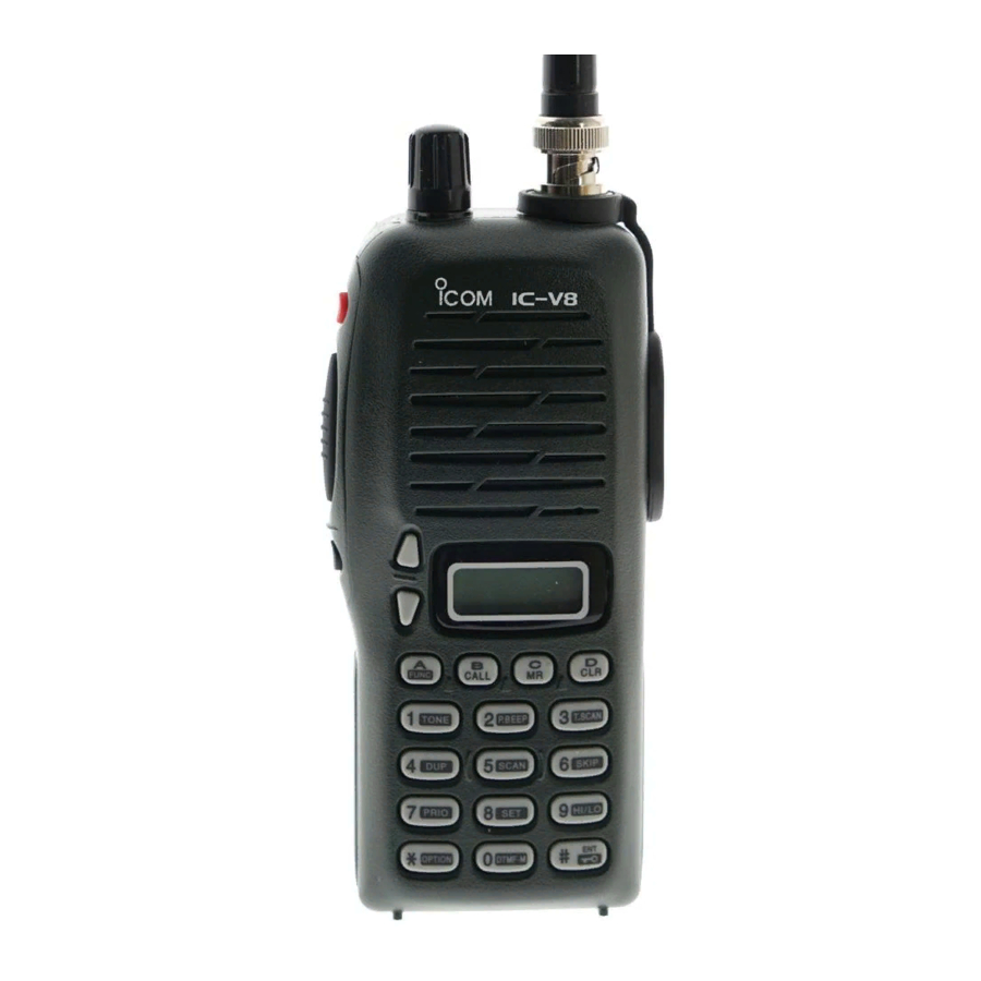
- Page 1 VHF TRANSCEIVER iC-v8...
- Page 2 INTRODUCTION This service manual describes the latest service information for the IC-V8 at the time of publication. To upgrade quality, all electrical or mechanical parts and internal circuits are subject to change without notice or oblig- ation. DANGER NEVER connect the transceiver to an AC outlet or to a DC power supply that uses more than 10.3 V.
- Page 3 TABLE OF CONTENTS SECTION 1 SPECIFICATIONS SECTION 2 INSIDE VIEWS SECTION 3 DISASSEMBLY INSTRUCTIONS SECTION 4 CIRCUIT DESCRIPTION 4 - 1 RECEIVER CIRCUITS ....................4 - 1 4 - 2 TRANSMITTER CIRCUITS .................... 4 - 2 4 - 3 PLL CIRCUIT ........................4 - 3 4 - 4 OTHER CIRCUITS ......................
- Page 4 SECTION 1 SPECIFICATIONS ‘ ‘ GENERAL • Frequency coverage Version Receive Transmit [USA] 144.000–148.000 MHz 136.000–174.000 MHz* [GEN] 136.000–174.000 MHz* *Specifications Guaranteed: 144–148 MHz only • Type of emission : F2D/ F3E • Frequency stability : ± 10 ppm (–10˚C to +60˚C; +14˚F to +140˚F) •...
- Page 5 SECTION 2 INSIDE VIEWS TOP VIEW BOTTOM VIEW Antenna swtching circuit (D2, D8: MA77) Power amplifier (Q1: 2SK3476) Antenna swtching circuit (D1: MA77) RF amplifier (Q12: 3SK274) 1st mixer IC3A: NJM12902V (Q13: 3SK274) Q37: DTA144EU FM IF IC (IC2: TA31136FN) Crystal filter FI1, Fl3: FL-298 IF amplifier...
- Page 6 Count on us! S-13802MZ-C1 1-1-32, Kamiminami, Hirano-ku, Osaka 547-0003, Japan © 2001 Icom Inc.
Need help?
Do you have a question about the iC-v8 and is the answer not in the manual?
Questions and answers