Sign In
Upload
Download
Table of Contents
Contents
Add to my manuals
Delete from my manuals
Share
URL of this page:
HTML Link:
Bookmark this page
Add
Manual will be automatically added to "My Manuals"
Print this page
×
Bookmark added
×
Added to my manuals
Manuals
Brands
Conair Manuals
Temperature Controller
Thermolator TW-S
User manual
Conair Thermolator TW-S User Manual
Hide thumbs
1
2
3
4
5
6
7
8
9
10
11
12
13
14
15
16
17
18
19
20
21
22
23
24
25
26
27
28
29
30
31
32
33
34
35
36
37
38
39
40
41
42
43
44
45
46
47
48
49
50
51
52
53
54
55
56
57
58
59
60
61
62
63
64
65
66
67
68
69
70
71
72
73
74
75
76
77
78
79
80
81
82
83
84
85
86
87
88
89
90
91
92
93
94
95
96
97
98
99
100
101
102
103
104
105
106
107
108
109
110
111
112
113
114
115
116
117
118
119
120
121
122
123
124
125
126
127
128
129
130
131
132
133
134
135
136
page
of
136
Go
/
136
Contents
Table of Contents
Troubleshooting
Bookmarks
Table of Contents
Ta B Le of C Onte NT S
Table of Contents
I N T R O D U C Ti O N
Purpose of the User Guide
How the Guide Is Organized
Your Responsibilities as a User
How to Use the Lockout Device
Des Crip T IO N
Ty Pic al a Pp L IC a T Io N S
Typical Applications
Wha T I S the T He Rmo la to R T W-S a Nd T W- P
H Ow Th E TW- S a Nd TW- P S E Ri E S D I Rec T in Jec T I on wo R Ks
H O W Th E C L O S E D C Ir C U It wo R K S
How the Closed Circuit Works
H O W Th E C L O S E D C Ir C U It S E P a R a T E so U R C E wo R K S
How the Closed Circuit Separate Source Works
TW-S Contr Ol Fe Atur es Vs TW-V a Nd T W-P
TW-P C on T R O L Fe a T U R E S V S T W-V a N D TW-S
TW-P Control Features Vs TW-V and TW-S
Sp Ecif Ications: T W-S
S Pe C if IC a Ti O Ns : T W- P
Specifications: TW-P
Options
TW-P Features and Options
I Nst a Llati on
U Np Ac King T H E B O X es
Unpacking the Boxes
Pr Epar in G F O R in S T a Ll a T Io N
Preparing for Installation
Fl Uid Distrib U Tio N Pip Ing
Rig Gin G
Ins Talla T Ion - E Le C T R I C a L
C Onn Ec Tin G P R O C E S S a Nd Wa T E R S Uppl y L I N E S
Connecting Process and Water Supply Lines Without Purge
Mold Purge Valve Connections
O Ptio N al M Ol D Pu R Ge Va L Ve C O Nnec T Ion S
C Onn Ec Tin G T H E M a in Po W E R so Ur C E
Connecting the Main Power Source
Te St in G T He in S T a Ll a Ti O N
Testing the Installation
Init Ial Set U P
Initial Setup
Operating Mode
Te Mp er a T U R E un It S
Temperature Units
S Et Poin T
Setpoint
A Lar M Point S
Alarm Points
O Peratio N
T He TW-S Co Ntro L
Th E T W- P C on T R O L
The TW-P Control
C Ont Ro L Le R Op Era Tin G Button S
Te Mpe Ra Tu R E DI S Pl Ays
D Ef Ault D Is P L a y
Default Display
O Perating L Igh Ts
S T a Rt in G T He T H E R M O L a to R
Starting the Thermolator
S T O P P Ing T He Th E R M O L a T O R
Stopping the Thermolator
Pr Ogr am M en U
Pr Ogr am M en U It E M S
Pr Oce Ss Cool D O Wn Seq Uenc E I ni Tia Tio N
Pu Mp Runn Ing Ho Ur D Is Pla y
SPI Comm un Ica T Ion S (Op Tio Na L)
SPI O P Tion Pa R am Et E Rs
M Odb Us Op Tio N Pa Ra M Et Ers
M Odb Us RTU (Opti Ona L )
Mod Bu S R Eg I S T er S
Using the Optional Mold Purge Option
C Onair TW- P T H E R M O L a T O R
Conair TW-P Thermolator
Ma Inten Anc E
Maint Enanc E O F y O U R T H E R M O L a T O R
Maintenance of Your Thermolator
Pr Even Ta Tive M a in T E Na N C E Sc He Dul E
Preventative Maintenance Schedule
A Cce Ss Ing T H E T He R M O la T O R Encl O S U R E
Accessing the Thermolator Enclosure
R Em Ovin G T H E P U M P M O T O R a N D Se a L (1/2 to 2 Hp, any Frequency and 3 HP, 60 Hz Units)
(1/2 to 2 Hp, any Frequency and 3 HP, 60 Hz Units)
Re Mo Vin G T He Pu Mp Mot or a Nd S Eal ( 3 H P, 50H Z and 5 to 10 Hp, an y Fr Equency Units)
Re as Semb Li N G P um P M Ot or a Nd Seal ( 3 H P, 50H Z and 5 to 10 Hp, an y Fr Equency Units)
Reassembling Pump Motor and Seal
Re Pl Aci N G Th E C on Tr O L L E R Boa Rd S
Tro Uble S H Oot I N G
Tr O U B L E Sh O O T I N G
Before Beginning
B Ef or E B Eg I N ni N G
A few Words of Caution
A few Wor D S O F C a U Ti O N
Identifying the Cause of a Problem
Ide Ntif y Ing T H E C a U S E O F a P R O Bl E M
Controller Alarms
C Ont R Oller al a R M S
Controller Control Fault Logic
C Ont R Oller C O N Tr O L Fa U L T L O G I C
Unit Faults
U Nit Fau Lt S
Unit will Not Power up
U Nit W Ill N O T Po W E R U P
Troubleshooting
Tr Ou B Les H Oo T in G
Replacing the Heater Contactor
R Eplac in G T He H E a te R C O Nt a C T O R
Checking the RTD
C Hec Kin G Th E RT D
Repairing Cooling Valves
R Epair in G C O Ol in G Va L V es
Va Lv es
Disassembly of Alternate Direct Acting Solenoid Valves
Alternate Pilot Operated Solenoid Valves
A Lt er N a T E P Il O T O P E R a T E D S O L E N O I D Va L V E S
Replacing Immersion Heaters
R Eplac in G IM M er S Io N H E a T E R S
Removing the Pump
R Em Ovin G T H E P U M P
Appendix
Appendix
PID Parameters
Setting the Security Passcode
Appendix
Plumbing Diagram
Plumbing Curves
Appendix
Service Parts
Appendix
External Interfaces
Appendix
Pressure Switch Settings
Appendix
Mold Purge Installa Tion Instructions
Appendix
Flo Wmeter Installa Tion Instructions
Advertisement
Quick Links
1
Alarm Points
2
Controller Alarms
Download this manual
www.conairgroup.com
U S E R G U I D E
UGH056-0917
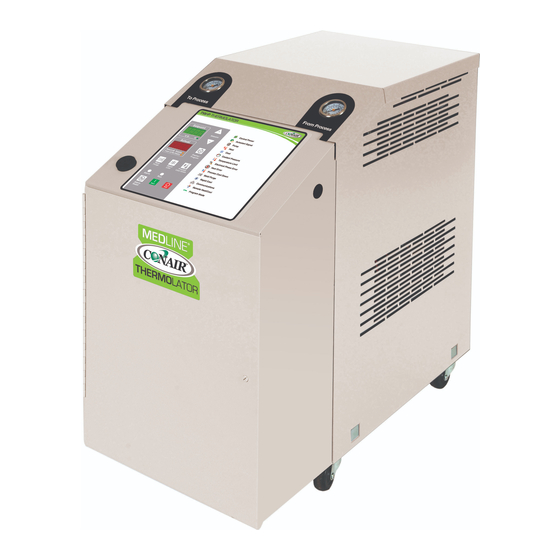
Thermolator
TW-S and TW-P
®
Temperature Control Units
TW-S
TW-P
Corporate Office: 724.584.5500 l Instant Access 24/7 (Parts and Service): 800.458.1960 l Parts and Service: 814.437.6861
Table of
Contents
Previous
Page
Next
Page
1
2
3
4
5
Advertisement
Chapters
Ta B Le of C Onte NT S
3
Des Crip T IO N
13
I Nst a Llati On
23
O Peratio N
37
Ma Inten Anc E
59
Tro Uble S H Oot I N G
73
Table of Contents
Need help?
Do you have a question about the Thermolator TW-S and is the answer not in the manual?
Ask a question
Questions and answers
Related Manuals for Conair Thermolator TW-S
Temperature Controller Conair Thermolator TW-P User Manual
(136 pages)
Temperature Controller Conair UGD031/0106 User Manual
For process air heater, 30 to 270 kw. (97 pages)
This manual is also suitable for:
Thermolator tw-p
Table of Contents
Save PDF
Print
Rename the bookmark
Delete bookmark?
Delete from my manuals?
Login
Sign In
OR
Sign in with Facebook
Sign in with Google
Upload manual
Upload from disk
Upload from URL


Need help?
Do you have a question about the Thermolator TW-S and is the answer not in the manual?
Questions and answers