Table of Contents
Advertisement
I
NSTALLATION
NSW (Head Office)
7 Columbia Court
Norwest Business Park
Baulkham Hills NSW 2153
Ph:
(02) 9899-4155
Fax:
(02) 9899-4156
Notifier Inertia Pty Ltd (A.C.N 002 692 962)
A PITTWAY COMPANY
A PITTWAY COMPANY
www.inertia.com.au
A
P
ND
ROGRAMMING
QLD
16 Lucy St
Moorooka
Qld 4104
Ph:
(07) 3892-6444
Fax:
(07) 3892-6455
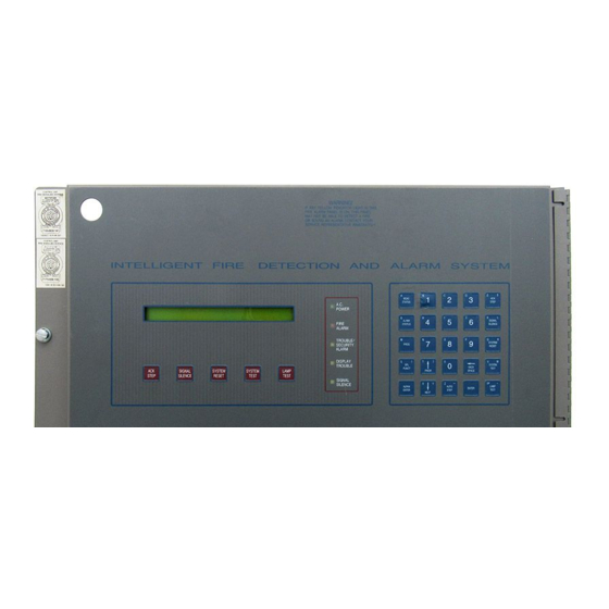
1010
2020
I
NTELLIGENT
D
ETECTION AND
A
LARM
S
OFTWARE
R
EVISION
VIC
Unit 2 297 Ingles St
Port Melbourne
Vic 3207
Ph:
(03) 9681-9929
Fax:
(03) 9681-9930
M
ANUAL
F
IRE
S
YSTEM
V
3.0
ERSION
AUS 1
Advertisement
Table of Contents


Need help?
Do you have a question about the 1010 and is the answer not in the manual?
Questions and answers