Notifier AFP-200 Instruction Manual
Intelligent fire detection and alarm system
Hide thumbs
Also See for AFP-200:
- Installation manual (196 pages) ,
- Manual (12 pages) ,
- Manual (2 pages)

Related Manuals for Notifier AFP-200


Summary of Contents for Notifier AFP-200
- Page 1 One Fire-lite Place Northford, CT 06472 (203) 484-7161 Fax: (203) 484-7118 Document 15511 10/11/99 Revision: PN 15511:F2 ECN 99-453...
-
Page 3: Table Of Contents
VERVIEW 1.1 Agency Standards and Compliance ..........6 1.2 Related Documentation ..............7 1.3 General Description ................7 1.4 AFP-200 Features ................8 1.5 Controls and Indicators ..............9 1.5.1 Membrane Panel ................. 9 1.5.2 Local Sounder ................9 1.5.3 Output Circuits ................9 1.5.4 Relays .................. - Page 4 4.12 Intelligent Detector Functions ............63 4.13 Time Functions ................65 4.14 Coding Operation (NAC only) ............65 4.15 Pre-signal/PAS Operation .............. 65 4.16 Special System Timers ..............66 4.17 Style 6 Operation ................66 AFP-200 Instruction PN 15511:F2 10/11/99...
- Page 5 A – S ........71 PPENDIX UPPLY ALCULATIONS The Main Power Supply ................. 72 Calculating the AFP-200 System Current Draw ........73 Calculating the Battery Size ..............75 B – NFPA S ..........77 PPENDIX TANDARDS Specific Requirements ................77 Mounting Instructions ................
- Page 6 Notifier DACT). NFPA 72-1993 Local Fire Alarm Systems. NFPA 72-1993 Auxiliary Fire Alarm Systems (requires 4XTM or RTM-8). NFPA 72-1993 Remote Station Fire Alarm Systems (requires 4XTM or Notifier 911ACDACT). NFPA 72-1993 Proprietary Fire Alarm Systems (Protected Premises Unit). Marine Approvals...
- Page 7 To obtain a complete understanding of AFP-200 specific features or to become familiar with related functions in general, refer to the documentation listed in Table 1.2-1 below. The Notifier document (DOC-NOT) chart provides the current document revisions. t t i...
- Page 8 • Abort – four options • Marine cabinet option (CAB-AM) Note: Unless otherwise notated, general terms are used throughout this manual to reference the specific part numbers shown in the table below: AFP-200 Instruction PN 15511:F2 10/11/99...
-
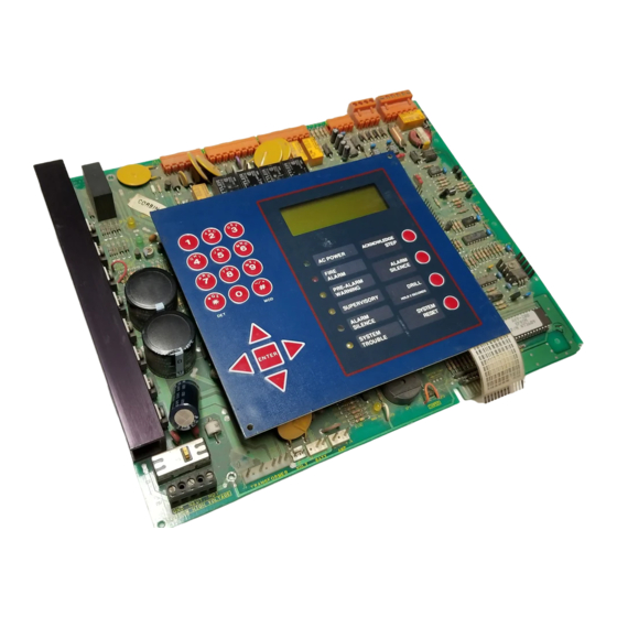
Page 9: Membrane Panel
The AFP-200 membrane panel includes windows for the Liquid Crystal Display (LCD) and six LEDs. The control panel has 21 keys, including a 12-key alphanumeric pad, similar to a telephone keypad. Slide-in labels for the six LEDs and the four main operator switches are included. Refer to Figure 1 for the location of switches and LEDs. - Page 10 (shown with dress panel removed) AFP-200 Instruction PN 15511:F2 10/11/99...
-
Page 11: Components
At the heart of the AFP-200 control panel, the circuit board contains the system’s central processing unit (CPU), power supply, and other primary components. It is delivered pre-mounted in the cabinet (see below). The circuit board mounts in a compact (16.125" x 14.5" x 5.5") ®... - Page 12 Slide-in labels are provided for switch and LED description. Two 100 VA transformers and connector. The cabinet provides space for 7 AH or 12 AH batteries (for 17 AH batteries use the BB-17 battery box). Batteries must be ordered separately. AFP-200 Instruction PN 15511:F2 10/11/99...
-
Page 13: Udact
24 VDC (nominal) connections are required. The UDACT is capable of reporting the status of 89 zones when used with the AFP-200. The AFP-200 requires software PN 73609 or higher when using a UDACT. Refer to Appendix B of this manual and the UDACT Manual for additional information. - Page 14 The CMX Series Control Modules and the MMX Series Monitor Modules provide an interface between the AFP-200 control panel and conventional initiating and notification devices. All module types respond to an address that is set by the installer with built-in rotary decimal switches. A flashing LED indicates power is applied.
- Page 15 The N-ELR Resistor Assortment is required for use in Canada. Resistors can be used for the supervision of an MMX Monitor Module or CMX Control Module circuit. Refer to Document 15453 for more information. Polarizing devices used in conjunction with releasing circuits. AFP-200 Instruction PN 15511:F2 10/11/99...
- Page 16 This section contains brief descriptions of annunciators that can be used with the AFP-200. For detailed information, refer to Appendix C and appropriate annunciator manuals for detailed wiring requirements. The Annunciator Control Module- The Annunciator Control 16AT or AFM-16AT contains 16...
- Page 17 Signal Silence and System Reset, a Time/Date display field, and a local piezo sounder with alarm/trouble resound. The LCD-80 can be mounted up to 6,000 feet from the AFP-200 control panel in an ABF-1 package. Up to four of these annunciators can be installed on a system (observe power limitations).
- Page 18 • For the AFP-200: 120 VAC, 50/60 Hz, 3.0 A. • For the AFP-200E: 220/240 VAC, 50/60 Hz, 1.5 A. • Wire size: minimum 14 AWG with 600 VAC insulation. • Maximum Charging Circuit – Dual Rate High Charge is 29.1 V @ 0.7 A; Normal Flat Charge is 27.6 V @ 0.5 A.
- Page 19 Follow instructions supplied with ring for mounting. AFP-200 Instruction PN 15511:F2 10/11/99...
- Page 20 AFP-200 Instruction PN 15511:F2 10/11/99...
- Page 21 The area should be readily accessible with sufficient room to easily install and maintain the control panel. Locate the top of the AFP-200 cabinet approxi- mately 60 inches above the floor with the hinge mounting on the left. Determine the number of conductors required for the devices to be installed.
- Page 22 (All DC power outputs are power-limited) Primary power required for the AFP-200 is 120 VAC, 50/60 Hz, 3 A and primary power required for the AFP-200E is 220/240 VAC, 50/60 Hz, 1.5 A. Overcurrent protection for this circuit must comply with Article 760 of the National Electrical Code (NEC) and/or local codes.
- Page 23 (supervised and power-limited) The AFP-200 control panel provides a set of Form-C alarm and a set of Form-C trouble contacts rated for 2.0 A @ 30 VDC (resistive). The control panel also provides a Form-A supervisory contact rated for 2.0 A @ 30 VDC (resistive).
- Page 24 Note: If also using a DB-9 connector for upload/downlload connect a jumper between pin 4 and pin 6. Note: The EIA-232 printer interface may also be used with EDP-listed equipment, such as personal computers, to monitor the control panel for supplementary purposes. AFP-200 Instruction PN 15511:F2 10/11/99...
- Page 25 4) Set the DIP switches as follows: SP1-1: OFF SP1-2: ON SP1-3: OFF SP1-4: ON SP1-5: OFF SP1-7: ON SP1-8: OFF SP2-1: OFF SP2-2: OFF SP2-3: OFF SP2-4: OFF SP2-5: OFF SP2-7: ON SP2-8: OFF AFP-200 Instruction PN 15511:F2 10/11/99...
- Page 26 Connect RX (Pin 2) to TB4 terminal 3 Note: This configuration requires that the copy parameter of the CRT setup be changed to BCOPY (Refer to CRT configuration in Appendix I.) Note: For terminal interface and protocol information, refer to Appendix I. AFP-200 Instruction PN 15511:F2 10/11/99...
-
Page 27: Specifications
Through the communications loop, the control panel communicates with intelligent ionization, photoelectric, and thermal detectors. AFP-200 capacity includes up to 99 intelligent detectors and an additional combination of up to 99 addressable pull stations, control modules, and Monitor Modules. In addition, the control panel also supports four Notifica- tion Appliance Circuits and up to 99 programmable relays. - Page 28 Measure by disconnecting loop out and return at the control panel, shorting the two leads of communications loop return, and metering loop out. For detailed wiring requirements, refer to Appendix F. Total length of the communications loop pair cannot exceed 10,000 feet (12 AWG). AFP-200 Instruction PN 15511:F2 10/11/99...
-
Page 29: Power
Connect (–) to TB 6-5 (Supervised and power-limited – meets NFPA 72-1993 Style 4 requirements) Note: The maximum number of devices between isolator modules is 25. ISO-X devices are not required to meet NFPA Style 4. AFP-200 Instruction PN 15511:F2 10/11/99... - Page 30 Connect Loop Return to TB 6-4 (+) and 6-6 (–). (Supervised and power-limited – meets NFPA 72-1993 Style 6 requirements) Note: The maximum number of devices between isolator modules is 25. ISO-X devices are not required to meet NFPA Style 4. AFP-200 Instruction PN 15511:F2 10/11/99...
-
Page 31: The Isolator Module
Zone 2, a trouble signal(s) will be generated for that device. No T–tapping or branching is allowed on this circuit. The ratings and characteristics are the same as for a four- wire circuit meeting NFPA Style 6 requirements. AFP-200 Instruction PN 15511:F2 10/11/99... - Page 32 Do not allow the shield drain wire to enter the system cabinet or the conduit. Connect the drain wire to the termination point of the conduit run. Note: The conduit cannot be longer than 20 feet. Must employ metal conduit and a metal box. Cabinet AFP-200 Instruction PN 15511:F2 10/11/99...
- Page 33 Connect as shown in Figure 2-22 and 2-23. Connect as shown in Figure 2-24 and 2-25. The MMX-2 requires the additional connection of 24 VDC filtered, regulated and resettable power on MMX-2 terminals 3 (–) and 4 (+). AFP-200 Instruction PN 15511:F2 10/11/99...
- Page 34 The MMX-2 Monitor Module is an addressable module used to monitor a single Initiating Device Circuit of two-wire smoke detectors. The monitored circuit may be wired an NFPA Style B (Class B) or Style D (Class Reference the Device Compatibility Document for compatible two-wire smoke detectors. AFP-200 Instruction PN 15511:F2 10/11/99...
- Page 35 Heat Detector Four-wire detector power Note: Maximum initiating device circuit Loop Out resistance is 20 ohms. 24 V (+) TB1-5 SLC (+) TB 6-3 24 V (–) TB 1-6 SLC (–) TB 6-5 (supervised and power-limited) AFP-200 Instruction PN 15511:F2 10/11/99...
- Page 36 24 V (–) TB 1-6 SLC (–) TB 6-5 Supervised and Power-limited Note: For more information, refer to the MMX-2 Installation Instructions, Document M500-03-00. For a list of compatible devices, reference the Device Compatibility Document. AFP-200 Instruction PN 15511:F2 10/11/99...
- Page 37 Note: Maximum initiating device circuit filtered, resistance is 20 ohms. regulated and LOOP resettable power 24 V (+) TB1-5 SLC (+) TB 6-3 24 V (–) TB 1-6 SLC (–) TB 6-5 (supervised and power-limited) AFP-200 Instruction PN 15511:F2 10/11/99...
- Page 38 SLC (+) TB 6-3 24 V (–) TB 1-6 SLC (–) TB 6-5 (supervised and power-limited) Note: For more information, refer to the MMX-2 Installation Instructions, Document M500-03-00. For compatible devices, reference the Device Compatibility Document. AFP-200 Instruction PN 15511:F2 10/11/99...
- Page 39 UL-listed power supervision relay, wired as shown in Figure 2-28 and 2-29. The CMX includes a magnetic test switch located near the center front of the module. Activation of this switch will cause a short circuit indication for the Style B/D loop. AFP-200 Instruction PN 15511:F2 10/11/99...
- Page 40 2 A @ 30 VDC Inductive: 1 A @ 30 VDC (0.6 pf) 1 A @ 30 VDC (0.6 pf) 0.3 A @ 120 VDC (0.35 pf) Pilot Duty: 0.6 A @ 30 VDC (0.35 pf) AFP-200 Instruction PN 15511:F2 10/11/99...
- Page 41 : Do not loop wiring under any terminals. Break wire run to maintain supervision. 24 V (+) TB1-1 SLC (+) TB 6-3 SLC (–) TB 6-5 24 V (–) TB 1-2 (All circuits are supervised and power-limited.) AFP-200 Instruction PN 15511:F2 10/11/99...
- Page 42 Note: Do not loop wiring under any terminals. Break wire run to maintain supervision. 24 V (+) TB1-1 SLC (+) TB 6-3 24 V (–) TB 1-2 SLC (–) TB 6-5 (All circuits are supervised and power-limited.) AFP-200 Instruction PN 15511:F2 10/11/99...
- Page 43 2. The BGX-101L is factory preset with address 00. Set the address for the BGX-1010L by using a screw- driver to turn the rotary address switches on the MMX-101 to the desired address settings. BGX-101L (back view) SLC (+) TB 6-3 SLC (–) TB 6-5 AFP-200 Instruction PN 15511:F2 10/11/99...
- Page 44 3. Before installing the appropriate intelligent detector head, set the detector's address on the detector head with a small slotted screwdriver. Mark this address on the detector base and on the detector head. BX-501 Detector Base RA400Z Remote LED Annunciator AFP-200 Instruction PN 15511:F2 10/11/99...
-
Page 45: Optional Modules
The AFP-200 control panel has an option module slot, using locations J6, J7, and J8 on the circuit board. There are two optional modules available for the control panel, the 4XTM Transmitter Module and the RTM-8 Relay Module. Jumper JP5 must be cut before installation of an optional module to enable module supervision. - Page 46 RTM-8 (when the board is in place for installation) and the corresponding hole on the main circuit board. Standoffs 4XTM Option Board Main Board Insert screw here Standoffs Main Board RTM-8 Option Board Use metal screw and standoff here AFP-200 Instruction PN 15511:F2 10/11/99...
- Page 47 During trouble conditions, it is possible to obtain the circuit condition on the alarm reverse- polarity output. If this operation is desired, cut the TBL jumper (shown in Figure 2-34). (Polarities are shown in activated positions.) AFP-200 Instruction PN 15511:F2 10/11/99...
- Page 48 VAC. 1/8HP @120/240 VAC (100,000 CYC)1.5/0.8 A at 120/240 VAC, Pilot Duty 30,000 CYC. Contact Material: Silver Nickel, gold-plated 2. Refer to the power-limited label located on the AFP-200 cabinet door. Make a notation on the label for each circuit used as a nonpower-limited circuit. (Refer to the example on the label).
- Page 49 The AFP-200 control panel is completely field-programmable and requires no special software skills. Program- ming may be done in one of two ways: 1. Using the Autoprogram feature and the control panel keypad. is a convenient way to quickly bring the system on-line and to make changes to an existing system program.
-
Page 50: Clear
R, press the 7 key to step through 7, P, R and S. Stop on R and then press the right cursor key (not Enter). The custom labels are 19 characters long (the last character is forced to blank). AFP-200 Instruction PN 15511:F2... - Page 51 ) t l e i l e l i l a i l a i l a i e l i c t i c t i l l i r c t i y t i AFP-200 Instruction PN 15511:F2 10/11/99...
-
Page 52: Point Programming
@ @ @ @ @ @ @ @ @ @ @ @ S W @ B O 1 Program Change mode (refer to Section 3.2.3), so you can select zoning, silencing, type code, and Walk Test features. AFP-200 Instruction PN 15511:F2 10/11/99... - Page 53 Note: Rather than reentering the next point number, you can press the up or down key to display the next lower or higher existing point. The point display format and the method of editing are described in Section 3.2.2, Autoprogramming. AFP-200 Instruction PN 15511:F2 10/11/99...
-
Page 54: Password Change
Change Zone Label screen. If the zone is out of range, the software ignores the Enter key. Pressing the left cursor key returns to the Program Change screen. AFP-200 Instruction PN 15511:F2... -
Page 55: Zone Change
M A R C H @ T I M E If selecting Software Zone 99, you can program the Alert and Action Pre-Alarm. Refer to Appendix G for a detailed explanation of the Pre-Alarm function. AFP-200 Instruction PN 15511:F2 10/11/99... -
Page 56: Upload/Download
RELEASE CKT but no input device mapped to them. Note: If multiple devices fail the check, use the up/down keys to step through the devices. To correct any errors detected by the Check routing, return to point programming and correct the program errors. AFP-200 Instruction PN 15511:F2 10/11/99... -
Page 57: Status Change Operation
O R @ B A C K S P A C E @ T O the screen to the right. E S C A P E Press Enter to clear all verification tally counters. Backspace returns to the Status Change screen. AFP-200 Instruction PN 15511:F2 10/11/99... -
Page 58: Walk Test
"TEST 02" will be reported for that address. The installer should verify that no "TEST 02" or higher entries exist in the history file. AFP-200 Instruction PN 15511:F2 10/11/99... -
Page 59: Acknowledge/Step
It also turns on all LEDs, piezo, and LCD display segments for as long as the System Reset is held (lamp test). Any alarm or trouble that exists after System Reset will resound the system. AFP-200 Instruction PN 15511:F2... - Page 60 Sends a supervisory query on the LCD-80 interface and verifying proper response. • Refreshes the LCD and LCD-80 display and updating time. • Scans the keypad for System Reset or Enter. • Auto tests detectors. • Tests system memory. AFP-200 Instruction PN 15511:F2 10/11/99...
-
Page 61: Normal Operation
Alarms activate the general alarm relay and zone Z00. FLR@05@MAIN@BUILDING A typical alarm display is shown in the screen to the 1 1 : 1 3 A @ 1 2 / 2 5 / 9 7 @ M 3 7 right. AFP-200 Instruction PN 15511:F2 10/11/99... -
Page 62: Trouble Operation
Trouble monitor-type MMX modules monitor remote power supplies or other external equipment. Operation is similar to trouble operation but with the following differences: • The display status banner is ACTIVE. • The type code is TROUBLE MON. • The modules latch. • The modules may have control-by-event. AFP-200 Instruction PN 15511:F2 10/11/99... -
Page 63: Releasing Functions
Ionization detectors used in duct applications must be set to high sensitivity. The system can be programmed to automatically force the smoke detectors to their minimum sensitivity (2.0%) during the “day.” For more information, refer to Section 4.13, Time Functions. AFP-200 Instruction PN 15511:F2 10/11/99... - Page 64 1.00% per foot of obscuration (High level), and has now reached the Alert level programmed for 50% of that, or 0.50% per foot. The 50% is a real-time display and may change. Alert Pre- Alarms automatically restore. AFP-200 Instruction PN 15511:F2 10/11/99...
-
Page 65: Time Functions
If signal silence occurs, the timer is frozen. If the timer expires, Zone 90 goes false. The alarm relay and transmitter are delayed if PAS is selected, but are not delayed for pre-signal operations. AFP-200 Instruction PN 15511:F2... - Page 66 The control panel latches the trouble and displays it until System Reset. The LCD display shows STYLE 6 trouble type. Style 7 requires use of the ISO-X isolator modules (refer to Chapter 2). AFP-200 Instruction PN 15511:F2 10/11/99...
- Page 67 The sequence of points is detector points 01-99, module points 01-99, Notification Appliance Circuits 01-04, system parameters, and then software zones 01-99. Refer to the follow- ing pages for examples of the Read Status display. AFP-200 Instruction PN 15511:F2 10/11/99...
- Page 68 P R E S I G N A L @ D E L A Y • PAS=YES (could be NO) indicates that Positive D E L A Y = 1 8 0 Alarm Sequence operation is selected in the pro- PAS=YES @@@@@@@Z90 gram. AFP-200 Instruction PN 15511:F2 10/11/99...
- Page 69 A C T I O N = 7 0 % @ O F @ A L A R M reaches it's Pre-Alarm threshold to indicate an incipient alarm, or the need for detector maintenance. @@@@@Z99 Zone 99 can be mapped to any control point. AFP-200 Instruction PN 15511:F2 10/11/99...
- Page 70 The control panel also has a non-erasable "shadow history" file that always contains the last 650 events in time. To read this file: press 8; then, press Enter. To print this file: press 9; then, press Enter. AFP-200 Instruction PN 15511:F2...
- Page 71 4) Selecting the proper batteries for your system. The control panel requires connection to a separate, dedicated AC branch circuit (120 VAC for AFP-200 and 220/240 VAC for AFP-200E), which must be labeled FIRE ALARM. This branch circuit must connect to the line side of the main power feed of the protected premises.
- Page 72 5. The total power supply load is limited to 5.0 A. Using Table A-3, verify that the subtotal for Calculation Column 2 is less than 5.0 A. 5.0 A Total System 0.5 A 2.5 A combined combined 1.5 A 2.5 A AFP-200 Instruction PN 15511:F2 10/11/99...
- Page 73 Use Table A-3 to calculate current draws as follows. 1) Enter the quantity of devices in all three columns. 2) Enter the current draw where required. Refer to the Notifier Device Compatibility Document for compatible devices and their current draw.
- Page 74 Table A-3 contains three columns for calculating current draws. For each column, calculate the current and enter the total (in amps) in the bottom row. When finished, copy the totals from Calculation Column 2 and Calculation Column 3 to Table A-4. Notes referenced in Table A-3 are listed on the next page. AFP-200 Instruction PN 15511:F2 10/11/99...
- Page 75 Notes for Table A-3: 1) Refer to the Notifier Device Compatibility Document for compatible devices and their current draws. 2) For non-English language systems, the LCD-80TM (Terminal Mode) standby current is 0.100 A. 3) Do not enter current for NAC #3 and NAC #4 in Table A-3 if powering these circuits from an AVPS-24.
- Page 76 7 AH to 17 AH range. Table A-5 contains information, such as the battery size and location, for the batteries required to power the control panel if an AC power loss occurs. Note: 15 AH to 17 AH batteries require the BB-17 or other UL-listed external battery cabinet. AFP-200 Instruction PN 15511:F2 10/11/99...
- Page 77 Appendix. The minimum system components required for compliance with the appropriate NFPA standard are listed below. • AFP-200 Control Panel containing the main circuit board, cabinet (backbox and door), main supply trans- former and power supply. • Batteries (refer to Appendix A for standby power requirements).
- Page 78 Notifier 911AC – for connection to a Central Station Receiver or Protected Premises Receiving Unit. This unit must be installed as shown in Figure B-1. For additional information on the 911AC, refer to Document 74-06200-005. Because the 911AC does not mount in the control panel backbox, all connections must be in conduit, less than 20 ft.
- Page 79 Cores PN 29090 AFP-200 UDACT in ABS-8R AFP-200 Cabinet (shown with cover removed) (Protected Premises Unit) Connect the Universal Digital Alarm Communicator/Transmitter (UDACT) according to the directions given in the UDACT Manual. Check the following items before powering the UDACT or control panel: •...
- Page 80 All connections are nonpower-limited and supervised. This application is not suitable for separate transmission of sprinkler supervisory or trouble conditions. Notes: 1. Maximum loop resistance allowed for wiring from control panel to Municipal Box. 2. Cut JP5 on control panel circuit board. AFP-200 Instruction PN 15511:F2 10/11/99...
- Page 81 Instruction Manual for Remote Station Receiver Model RS-82 – – – – – Remote Alarm Remote Trouble (polarity shown is for normal standby) 4XTM Transmitter Module (activated polarities shown) Note: Cut Jumper JP5 on the control panel circuit board. AFP-200 Instruction PN 15511:F2 10/11/99...
- Page 82 Remote Station) Alarm/Trouble Polarity Reversal Remote Station JP1 must be cut Alarm only Polarity Reversal Remote Station must be cut – Note: Cut Jumper JP5 on control panel circuit board. AFP-200 Instruction PN 15511:F2 10/11/99...
- Page 83 ) - ( ) - ( The AFP-200 must be programmed for ACS annunciation mode and must have the switch (SW2) on the main circuit board set for ACS mode. The ACS interface will automatically transmit General Alarm, General Trouble and General Supervisory signals and will receive Acknowledge, Silence, and Reset commands automatically from the AM2020/AFP1010 control panel.
- Page 84 Information is transmitted using annunciator addresses 1 and 2. The EIA-485 interface will allow up to 32 annunciators (all but two must be in receive-only mode), over distances of up to 6,000 ft. (check power limitations). AFP-200 Instruction PN 15511:F2 10/11/99...
- Page 85 Annunciator on the same control panel will alter the assignments of the yellow LEDs on ACS Points 3, 4, 5, 6, 7 and 8. Assignments with the UDACT are Point 3=Program Mode, Point 4=Supervisory, Point 5=Bell Trouble, Point 6=Prealarm/Maintenance Alert, Point 7=Low Battery and Point 8=AC Fail. System Trouble excludes AC power fail. AFP-200 Instruction PN 15511:F2 10/11/99...
- Page 86 Notes: 1. The National Standard of Canada (CAN/ULC-5527) requires a dedicated display to use yellow visual indicators to show the status of supervisory inputs. Notifier annunciators intended for Canadian Supervisory Service are: ACM-16ATCS4, ACM-16ATCS, ACM-16ATY, ACM-32ACS8, ACM-32ACS, and ACM-32AY. 2. On address 2, LED number = point number – 56.
- Page 87 Note: The LCD-80s require connection of operating power! Connect 24 V power to the AFP-200 TB1 terminal 3 (+) and TB1 terminal 4 (–). Power connections are supervised and power-limited. • Power-limited and supervised. (must set DIP Switch SW3-1 AND SW3-2 "OFF" on •...
- Page 88 2 must be set to "OFF". Set the LCD-80 to a size of 128 points. To use a 40-character display; set SW5 OFF and SW6 ON. To use a 20-character display; set SW5 ON and SW6 OFF. AFP-200 Instruction PN 15511:F2...
- Page 89 + - + - + - B + B - B + B - B + B - B + B - N O C N O N C C N O N C C TB1-3 (+) TB1-4 (–) AFP-200 Instruction PN 15511:F2 10/11/99...
- Page 90 Refer to the ACS Manual and the LDM Manual for additional information. • Set SW2 on the control panel to the “ACS” position. Install 120 ohm terminat- ing resistor on last annunciator TB5-1 (+) TB5-2 (–) AFP-200 Instruction PN 15511:F2 10/11/99...
- Page 91 Soak is used to automatically shut off the releasing solenoids for a user-defined time after the zone turns them on. It may be programmed for zero (no soak timer), or 10 to 15 minutes. Use in NFPA 16 applications only. AFP-200 Instruction PN 15511:F2...
- Page 92 "MAN. RELEASE" – A type code assigned to an MMX Monitor Module which performs a manual release function. The MMX is connected to a UL-listed manual station such as the Notifier ARA-10 or NBG-10. It will override all Abort Switch modules that are active and programmed to the same releasing zone. All wiring is fully supervised, following the wiring instructions for the MMX modules described earlier in this document.
- Page 93 • For NFPA 13 and 15 applications, the soak timer must be disabled. • For NFPA 16 applications, the soak timer may be set to 10 or 15 minutes. • For UL-listed and FM approved Solenoid Release Valves, refer to the Device Compatibility Document. AFP-200 Instruction PN 15511:F2 10/11/99...
- Page 94 Terminate all unused circuits with a 4.7K ELR For a list of compatible solenoid valves, refer to the Device Compatibility Document. 24 VDC power REL-4.7K from AFP-200 Brown TB2-1 (+) Releasing Device (UL-listed) 24 VDC TB2-2 (–) SLC Loop to AFP-200 TB6-5 (–)
- Page 95 SLC to AFP-200 AFP-200 AFP-200, TB1-2 Alarm polarity shown * ELR model R-47K Supervised and Power-limited See Doc no. 15453 for additional information ** End-Of-Line Device REL - 47K Notes: 1. For releasing applications use an end-of-line device (part number REL-47K) with the CMX module. Use an end-of-line device (part number REL-4.7K) with the control panel releasing circuit (one of the four NACs).
- Page 96 For instructions on bypassing security zones for Burglar alarm type devices, refer to the Disable/Enable section in Chapter 3, Programming. The cabinet must be wired with the STS-200 security tamper switch kit as shown in Figure E-1. AFP-200 Instruction PN 15511:F2 10/11/99...
- Page 97 Wire security monitoring zones as shown in Figure E-2, “Typical Protected Premises Wiring for Central Station and Proprietary Burglar Alarm Applications.” The AFP-200 is supplied with a unique security keypad slide-in label for combination fire/burglary applications. This security label is identical to the standard slide-in label, except the fourth label position shows Security rather than Supervisory.
- Page 98 (A2143-00)* +24 VDC UL-listed Notification Appliance Configured as an Notification Appliance Circuit (do not break tabs) and programmed in the Protected Premises Unit. Supplemen- tary use only in UL-listed Systems. UL-listed 24 VDC Power Supply. AFP-200 Instruction PN 15511:F2 10/11/99...
- Page 99 , r i i l - c i t i n i i l - i n i i t i i l - c i f a i l i l - i l - AFP-200 Instruction PN 15511:F2 10/11/99...
- Page 100 The Pre-Alarm indication for this detector will restore automatically to normal if its sensitivity drops below Alert level. Zone 99 clears automatically when no Pre-Alarm conditions exist. • A subsequent alarm, or an Action level condition for this detector will clear the Alert indication. AFP-200 Instruction PN 15511:F2 10/11/99...
- Page 101 This can be done by programming ALERT=00% and only using the Action level. Also, if non-latching operation is desired, ACTION=00% can be selected to allow use of Alert level only. Note: Only the Action level will provide ACS point annunciation. AFP-200 Instruction PN 15511:F2 10/11/99...
- Page 102 Alert Pre-Alarm operation. If all sounder-bases are to activate on alarm, wire the power for these bases through two CMX relay contacts that will reverse the polarity to the B501BH bases on alarm. AFP-200 Instruction PN 15511:F2...
- Page 103 Note: An Alert signal is automatically sent to any of the four NACs that are not mapped to the alarm signal but are mapped to Z00 and Z98. After 5 minutes without an Acknowledge or Alarm Silence, the Alert signal becomes steady. AFP-200 Instruction PN 15511:F2 10/11/99...
- Page 104 CRT. A user-definable password is required to perform the Alter Status function. The functions described below are available when operating in Local Terminal Mode. The Terminal must be mounted in a UL-864 listed enclosure, a Notifier Rack-51, Rack-67 or arranged to provide equivalent protection against unauthorized use. •...
- Page 105 Remote Monitor mode operation only permits the user to perform the Read Status function. This mode can be used with UL EDP listed terminals, including personal computers using Notifier PK-200 release 2.0 software or terminal emulation software. It is also intended for terminals that are connected through modems connected through a public switched telephone network, such as the Notifier TP1-232 modem.
- Page 106 ****************************** EVENT HISTORY START*************************** ALARM: HEAT(ANALOG) DETECTOR ADDRESS 55 ZONE 55 3:10A 04/20/97 D55 ALARM: SMOKE(PHOTO) DETECTOR ADDRESS 29 ZONE 01 3:15A 04/20/97 D29 ACKNOWLEDGE 3:16A 04/20/97 SYSTEM RESET 3:17A Fri 04/20/97 ******************************* EVENT HISTORY END *************************** AFP-200 Instruction PN 15511:F2 10/11/99...
- Page 107 Enter the number of the detector, module, or bell circuit you wish to disable or enable. Example Notification Appliance Circuit (NAC) number 1. ENTER B01 Now Enabled, Enter E(Enable) / D(Disable) or Esc. to Abort AFP-200 Instruction PN 15511:F2 10/11/99...
- Page 108 Set Action/Alert enables the operator to set the AWACS Alert and Action levels. ENTER Set % of Alarm: Alert(T) and Action(N) Format: TxxNxx then Enter Enter the Alert and Action AWACS levels. Example: Alert level=50% and the Action level=70% T50N70 ENTER AFP-200 Instruction PN 15511:F2 10/11/99...
- Page 109 Aux Xmt Pace=Baud EIA Break=Off EIA Modem Control=Off EIA Disconnect=2 sec Aux Break=Off Aux Modem Control=Off Aux Disconnect=2 sec Comm Mode=Full Duplex Local=Off Recv <CR>=<CR> Recv <DEL>=Ignore Send ACK=On Send Line Term=<US> Send Block Term=<CR> Null Suppress=Off AFP-200 Instruction PN 15511:F2 10/11/99...
- Page 110 Programming Utility manual. Download operations which change the basic program of the control panel must be done with responsible service personnel in attendance at the control panel. After a program is downloaded, the control panel must be tested is accordance with NFPA 72-1993. AFP-200 Instruction PN 15511:F2 10/11/99...
- Page 111 AC Neutral (white): AVPS-24/AVPS-24E, TB1 terminal 4 connects to control panel TB7 terminal 2. Battery (–): Black wire from the battery cable connects to AVPS-24/AVPS-24E TB1 terminal 3. Battery (+): Red wire from the battery cable connects to AVPS-24/AVPS-24E TB1 terminal 2. AFP-200 Instruction PN 15511:F2 10/11/99...
- Page 112 Connect earth ground to TB1 terminal 6, connect AC hot to TB1 terminal 5, and connect AC neutral to TB1 terminal 4. 6. Battery Connections: Connect the battery (–) to AVPS-24/AVPS-24E TB1 terminal 3. Connect the battery (+) to AVPS-24/ AVPS-24E TB1 terminal 2. PN 71093 PN 71033 PN 75203 AFP-200 Instruction PN 15511:F2 10/11/99...
- Page 113 Refer to Figure 2-35 for additional information on this module. Figure K-1 below shows the RTM-8 Module installed in the AFP-200. Power-limited and nonpower-limited wiring must maintain a minimum distance of ¼ inch wire to wire. Note that a gap of ¾ inch exists between relay four and relay five. It is recommended that if using this module to drive both power-limited and nonpower-limited circuits, use the first four relays to drive power-limited circuits and the next four relays to drive nonpower-limited circuits.
- Page 114 Bell 6" Gong 24 VDC Red Agent Release Pull Station Bell 10" Gong 24 VDC Red Network Interface Board Notifier Remote Battery Charger 120 ohm End-of-Line Resistor 140 Degree F. Thermal Detector 2.2K End-of-Line Resistor 190 Degree F. Thermal Detector 27K End-of-Line Resistor 225 Degree F.
- Page 115 Notes AFP-200 Instruction PN 15511:F2 10/11/99...
- Page 116 Notes AFP-200 Instruction PN 15511:F2 10/11/99...
- Page 117 Notes AFP-200 Instruction PN 15511:F2 10/11/99...
- Page 118 Notes AFP-200 Instruction PN 15511:F2 10/11/99...
- Page 119 Notes AFP-200 Instruction PN 15511:F2 10/11/99...
- Page 120 Notes AFP-200 Instruction PN 15511:F2 10/11/99...
Need help?
Do you have a question about the AFP-200 and is the answer not in the manual?
Questions and answers