Advertisement
1 Product Overview
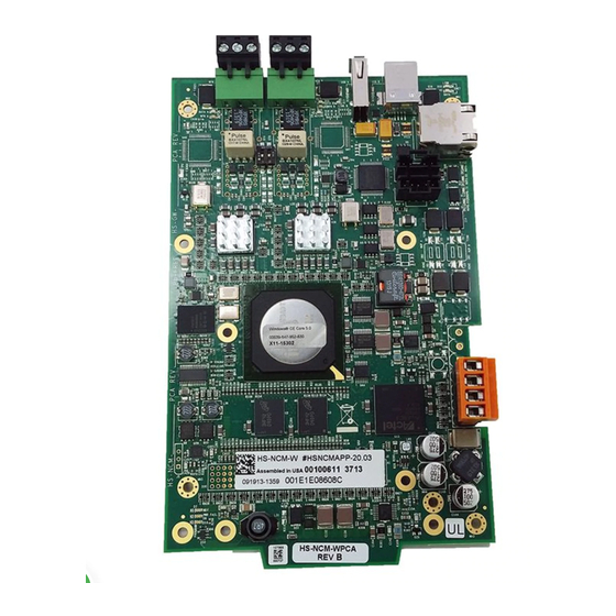
The High-Speed Network Communications Module (HS-NCM) provides a means for connecting specific Notifier fire
alarm control products to High-Speed NOTI•FIRE•NET™. There are six types of HS-NCMs available: HS-NCM-W for
connecting nodes with twisted-pair wire; HS-NCM-MF and HS-NCM-SF are used for connecting nodes with fiber-optic
cable; HS-NCM-WMF and HS-NCM-WSF are used for connecting nodes with fiber-optic cables to nodes with twisted-
pair wire; HS-NCM-MFSF for connecting nodes with multi-mode fiber cable to nodes with single-mode fiber cable. The
following equipment may be used with the HS-NCM:
UL 9th Edition*
•
NFS2-3030
•
NFS2-640
•
NFS-320
•
NCA-2
•
DVC-EM
•
ONYXWorks
* - Power for the HS-NCM for use with UL 9th Edition panels is provided via the NUP connection on the FACP itself or an external UL/ULC listed power supply.
** - Power for the HS-NCM for use with UL 8th Edition panels must be provided by a 24 VDC UL/ULC listed power supply.
†
The following revisions
of the UL 9th edition panels require a 24 VDC UL/ULC listed power source to power the HS-
NCM and can not be powered via the panel's NUP port
† The revision and assembly name can be found on the fire panel's circuit board.
‡ NUP Port connections are still required for communication between the HS-NCM and the fire panel.
NOTE: All wiring connections are supervised and power limited.
One HS-NCM can provide network communication for up to two nodes (including fire alarm control panels and network
annunciators).
Per UL 864 9th Edition, the HS-NCM uses Active Multiplex Type 3 Communication.
The HS-NCM can also be configured as a high-speed repeater for applications requiring distances beyond the specified
limits between two nodes. For configuration and setup information, refer to "HS-NCM Configuration" on page 5. For
limitations and network wiring information for the HS-NCM, refer to the High-Speed Noti•Fire•Net Manual.
For instructions on the additional capabilities available with the DVC-EM, refer to the DVC and DAA Series Installation
Manual.
•
Input power requirements: 24 VDC, 0.400 A, regulated, power-limited compatible power supply UL/ULC listed for
fire protective signalling use.
•
Communications circuit requirements: Refer to the High-Speed Noti•Fire•Net Manual for segment length limitations.
High-Speed Network Communications Module
‡
:
NFS-320
CPU2-640PCB Revision E or older
NFS2-640
CPU2-640PCB Revision E or older
NFS2-3030
CPU2-3030PCC Revision I or older
DVC-EM
DVC-EMPCB Revision F or older
DVC
DVC-PCA -All Revisions
NCA-2
NCA-2PCC Revision I or older
Product Installation Document
PN 54014:B2 04/25/2014 14-0370
UL 8th Edition**
•
NFS-3030
•
NFS-640
•
NCA
12 Clintonville Road
Northford, CT 06472-1610 USA
203-484-7161 • FAX 203-484-7118
www.notifier.com
Advertisement
Table of Contents

Related Manuals for Notifier HS-NCM


Summary of Contents for Notifier HS-NCM
-
Page 1: Product Overview
ONYXWorks * - Power for the HS-NCM for use with UL 9th Edition panels is provided via the NUP connection on the FACP itself or an external UL/ULC listed power supply. ** - Power for the HS-NCM for use with UL 8th Edition panels must be provided by a 24 VDC UL/ULC listed power supply. -
Page 2: Operations
Table 1 Voltage and Current Ratings for Communication Circuits NOTE: For use with the NFS-640, NFS2-640, NFS-320, NFS-3030, NFS2-3030, DVC-EM, NCA-2, and NCA, the HS-NCM must be connected via the NUP Ports! 2 The Network Communications Module for Wire (HS-NCM-W) - Page 3 Figure 2 HS-NCM-SF/MF/MFSF • Enables software and database upload/download over High-Speed Noti•Fire•Net. NOTE: When referring to fiber-optic cables, the term “MF” indicates a multi-mode fiber and the term “SF” indicates a single-mode fiber. HS-NCM Installation Document — P/N 54014:B2 04/25/2014...
-
Page 4: Programming
Port A and Port B assignment for the wire and fiber connections are set through VeriFire Tools. Refer to the VeriFire™ Tools CD on-line help file. NOTE: When referring to fiber-optic cables, the term “MF” indicates a multi-mode fiber and the term “SF” indicates a single-mode fiber. HS-NCM Installation Document — P/N 54014:B2 04/25/2014... - Page 5 “Network Node Session” of the VeriFire Tools Upload/Download screen is shown as “Local VeriFire” Double click the node to log in to the panel. Using the mouse, right click on the node connected to the HS-NCM being configured. A menu of available options is displayed. HS-NCM Installation Document — P/N 54014:B2 04/25/2014...
- Page 6 Select “HS-NCM Parameters”. The HS-NCM Parameters screen will be displayed listing HS-NCM defaults. HS-NCM Installation Document — P/N 54014:B2 04/25/2014...
- Page 7 Once connected to an FACP, the HS-NCM will evaluate the network programming of the fire panel and set it’s node address accordingly. When power is applied to the HS-NCM without connection via the NUP port to an FACP, the HS-NCM will automatically configure itself as a repeater and it’s node address will be defaulted to zero.
-
Page 8: Mounting Options
6.1 Mounting Options The HS-NCM is designed to mount in a variety of CAB-3/CAB-4 compatible chassis, in the NFS-320 enclosure, on a BMP-1 blank plate for dress panel mounting, or behind the DVC-EM in the CA-1 or CA-2 audio chassis. HS-NCM-W can be door-mounted;... - Page 9 6.2 Interconnecting the HS-NCM-W When wiring consecutive HS-NCM-W boards, note that wiring may enter or exit at Port A or Port B as shown in Figure 7. HS-NCM-W port-to-port wiring is polarity sensitive. Port A must be connected to Port B of the next HS-NCM-W. A HS- NCM-W may be connected to any of the following devices: •...
- Page 10 – + – + – + Note: Wiring from the HS-NCM-W that is installed outside the building: • Cannot exceed 1000m (3280 ft.). • Must be in conduit and is to be buried in a trench separate from any power lines.
- Page 11 Table 3 NOTI•FIRE•NET™ Connections: HS-NCM-MF/SF/MFSF 6.4 Mixing Wire & Fiber on One Network In some networks, it may be necessary to mix twisted-pair wire and fiber-optic cable—use a HS-NCM-WMF or HS- NCM-WSF as an interface between wire and fiber. Fiber ports are not polarity sensitive. However, port-to-port wiring for the HS-NCM wire connections are polarity sensitive.
- Page 12 6.5 Approved Cables and Distances for HS-NCM Applications The following table shows approved wiring cables that can be used with the HS-NCM and the maximum total distance allowed for each. Wire Type / Gauge Maximum Distance: Wire Type / Guage...
-
Page 13: Diagnostic Indicators
7 Diagnostic Indicators The HS-NCM has LEDs that serve as diagnostic indicators to help in troubleshooting and system connection. Refer to Table 5 for a list of diagnostic indicators and their descriptions. Refer to Figure 11 for diagnostic indicator locations. - Page 14 NFN wiring integrity and Port Mode mismatch. Refer to page 7 for Port Mode settings. ACTIVE Program Status Green Blinks On when a program on the HS-NCM is operating normally. PROGRAM Flash Programming Yellow Blinks On during Flash programming. DO NOT REMOVE...
-
Page 15: Supplemental Documentation
8 Supplemental Documentation The table below provides a list of document sources (manuals) containing additional information regarding the HS-NCM-W/MF/SF and the High-Speed Noti•Fire•Net products that it can connect to. For information on… Refer to… Part No. Fire Alarm Control Panels High-Speed Noti•Fire•Net Manual...
Need help?
Do you have a question about the HS-NCM and is the answer not in the manual?
Questions and answers