Table of Contents
Advertisement
Quick Links
INSTALLATION AND MAINTENANCE INSTRUCTIONS
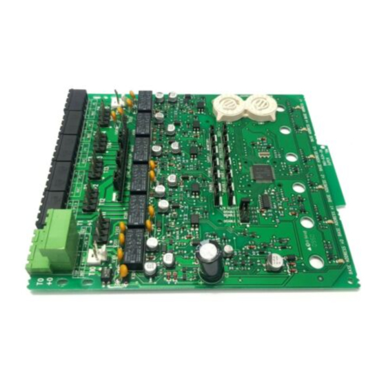
XP6-C
Six Circuit Supervised Control Module
SPECIFICATIONS
Normal Operating Voltage:
Stand-By Current:
Alarm Current:
Temperature Range:
Humidity:
Dimensions:
Accessories:
Wire Gauge:
Max. NAC Circuit Line Loss:
Power Rating Per Circuit (Speakers):
Max. NAC Current Ratings:
Table 1: Short Circuit Protection - UL 864 9th Edition Requirements
NOTICE TO USERS, INSTALLERS, AUTHORITIES HAVING JURISDICTION, AND OTHER INVOLVED PARTIES
This product incorporates field-programmable software. In order for the product to comply with requirements in the Standard for
Control Units and Accessories for Fire Alarm Systems, UL 864, certain programming features or options must be limited to specific
Program Feature or Option
Disabling short circuit
protection when a single
power supply is shared by
multiple NACs
BEFORE INSTALLING
If the modules will be installed in an existing operational system,
inform the operator and local authority that the system will be
temporarily out of service. Disconnect the power to the control
panel before installing the modules. This system contains static
sensitive components. Always ground yourself with a proper
wrist strap before handling any circuits so that static charges are
removed from the body. The housing cabinet should be metallic
and suitably grounded.
NOTICE:This manual should be left with the owner/user of this equipment.
GENERAL DESCRIPTION
The XP6-C Six Circuit Supervised Control Module is intended
for use in an intelligent alarm system. Each module is intended
for switching applications involving AC, DC, or audio, which
require wiring supervision. A common SLC input is used for all
modules. Each module has its own address. A pair of rotary code
switches is used to set the address of the first module from 01 to
N500-79-00
15-32 VDC
2.25 mA
35 mA (assumes all six relays have been switched once and all six LEDs solid on)
32°F to 120°F (0°C to 49°C); –10°C to 55°C (For EN54 applications only)
10 to 93% Non-condensing
6.8"H x 5.8"W x 1.25"D
CHS-6 Chassis; BB-25 Cabinet; BB-XP Cabinet; CAB-3 Series Cabinet, CAB-4 Series Cabinet
12-18 AWG
4 VDC
63 W @ 70.7 VAC; 50 W @ 25 VAC
For class B wiring systems, 3A
For class A wiring systems, 2A
values or not used at all as indicated below.
Permitted in
Possible Settings
UL 864 (Y/N)
No
Enable or Disable
short circuit
protection
Settings Permitted in UL 864
Enable short circuit protection when a single power
supply is shared by multiple NACs. Short circuit
protection can be disabled only when a power supply
is not shared by multiple NACs.
154. The remaining modules are automatically assigned to the
next five higher addresses. Provisions are included for disabling
a maximum of three unused modules to release the addresses to
be used elsewhere. Each module also has panel controlled green
LED indicators. The panel can cause the LEDs to blink, latch on,
or latch off.
In order to synchronize strobes, horn/strobes, and speaker/
strobes, a SYNC-1 accessory card (sold separately) must be used
with the XP6-C. See the SYNC-1 installation manual for details on
how to install.
Each module has terminals for connection to an external supply
circuit for powering devices on its NAC. Each supply must be
power limited and its voltage/current limits must be at or below
those specified. There is a short circuit protection monitor for
each module. This is provided to protect the external power sup-
ply against short circuit conditions on the NAC.
1
12 Clintonville Road
Northford, CT 06472-1653
Phone: 203/484-7161
I56-1805-012
Advertisement
Table of Contents

Related Manuals for Notifier XP6-C


Summary of Contents for Notifier XP6-C
- Page 1 In order to synchronize strobes, horn/strobes, and speaker/ and suitably grounded. strobes, a SYNC-1 accessory card (sold separately) must be used with the XP6-C. See the SYNC-1 installation manual for details on NOTICE:This manual should be left with the owner/user of this equipment. how to install.
- Page 2 (see Figure 4). There are two mounting options for XP6-C modules: • Up to six XP6-C modules can be installed on a CHS-6 in a CAB-3 Series, CAB-4 Series, or BB-25 cabinet.
- Page 3 Step 1: Insert the bottom edge of the XP6-C module down into a rear slot of the chassis. Step 2: Carefully swing the upper edge of the board towards the back of the chassis until it touches the short standoff attached to the chassis.
- Page 4 The XP6-C is capable of supporting Power must not be applied to the unit when changing 3 Class A, Style Z NACs. The XP6-C will only respond at the base functionality of the shunts. address, base address +2, and base address +4 (assuming no...
- Page 5 *Note: T0–TOP is reserved for SLC connections only (see Figure 8). An EOL relay must be used for every external power supply All power supplies, external to the cabinet (in which the XP6-C is (figures 9–12 are typical). The EOL relay coil should always be housed), should be connected to T0–T5 which are suitable con-...
- Page 6 EXTERNAL POWER (–) (–) – SUPPLY A2143-10 BASE ADDRESS – 6 7 8 9 (–) (–) – – – A2143-10 EOLR-1 A/B SELECT DISABLE 1 DISABLE 2 DISABLE 3 POWER-LIMITED TOP OF T0 AND SUPERVISED STATUS FROM PANEL OR INDICATORS –...
- Page 7 EOLR-1 (TYP) (–) (–) BASE ADDRESS 6 7 8 9 – – EXTERNAL (–) (–) – POWER SUPPLY A/B SELECT DISABLE 1 DISABLE 2 DISABLE 3 POWER-LIMITED TOP OF T0 AND SUPERVISED STATUS FROM PANEL OR INDICATORS – PREVIOUS DEVICE TO NEXT –...
- Page 8 – Increase the separation between the equipment and receiver. – Connect the equipment into an outlet on a circuit different from that to which the receiver is connected. – Consult the dealer or an experienced radio/TV technician for help. N500-79-00 I56-1805-012 © 2006 Notifier...
Need help?
Do you have a question about the XP6-C and is the answer not in the manual?
Questions and answers