
Related Manuals for Mitsubishi Electric FR-HC2-7.5K


Summary of Contents for Mitsubishi Electric FR-HC2-7.5K
-
Page 1: Instruction Manual
INVERTER FR-HC2 INSTRUCTION MANUAL High power factor converter FR-HC2-7.5K to 75K FR-HC2-H7.5K to H560K OUTLINE INSTALLATION AND WIRING PARAMETERS PROTECTIVE FUNCTIONS MAINTENANCE AND INSPECTION SPECIFICATIONS... -
Page 2: Safety Instructions
Thank you for choosing the Mitsubishi High Power Factor Converter. This Instruction Manual gives handling information and precautions for use of this equipment. Incorrect handling might cause an unexpected fault. Before using the converter, please read this manual carefully to use the equipment to its optimum. - Page 3 (2) Trial run (6) Disposal CAUTION CAUTION Before starting the operation, each parameter must be The converter must be treated as industrial waste. confirmed and adjusted. A failure to do so may cause (7) General instruction some machines to make unexpected motions. Many of the diagrams and drawings in this Instruction ...
-
Page 4: Table Of Contents
Terminal arrangement of the main circuit terminal ............... 28 2.6.3 Cable sizes of the main control circuit terminals and earth (ground) terminals ......31 Wiring of main circuit (FR-HC2-7.5K to 75K, FR-HC2-H7.5K to H220K) ....... 34 2.7.1 Connection diagram (when using with the FR-A700 series) ............34 2.7.2 Wiring of main circuit ........................ - Page 5 2.9.1 Connection diagram (when using with the FR-A700 series)............47 2.9.2 Wiring of main circuit ........................48 2.10 Notes on earthing (grounding)............53 2.11 Compatible inverter for the high power factor converter....54 2.11.1 Applicable inverter capacity ......................54 2.11.2 Inverter parameter settings......................55 2.12 Wiring of several inverters to one converter ........
- Page 6 3.4.13 DU/PU, terminal FM/AM monitor display selection (Pr. 46 to Pr. 48, Pr. 50, Pr. 52, Pr. 54) ..86 3.4.14 Operation selection at instantaneous power failure (Pr. 57)............89 3.4.15 Free parameter (Pr. 58, Pr. 59) ....................90 3.4.16 Key lock selection of operation panel(Pr. 61) ................90 3.4.17 Retry function (Pr.
- Page 7 SPECIFICATIONS Rated specifications ............... 148 Common specifications ..............149 Outline dimensions ................. 150 6.3.1 Converter (FR-HC2) ........................150 6.3.2 Reactor 1 (FR-HCL21)........................ 157 6.3.3 Reactor 2 (FR-HCL22)........................ 165 6.3.4 Difference between the reactor 1 (FR-HCL21) and the reactor 2 (FR-HCL22)......172 6.3.5 Outside box (FR-HCB2)......................
-
Page 8: Outline
OUTLINE This chapter explains the "OUTLINE" for use of this product. Always read the instructions before using the equipment. Pre-operation instructions ............2 Converter and peripheral devices ..........7 Precautions for selecting peripheral devices ......8... -
Page 9: Pre-Operation Instructions
REMARKS Inverter parameters must be set. The parameter settings differ by the inverter series. Refer to page 55 for details. Power supply harmonic suppression effect (Example) FR-HC2-7.5K (Condition) Load: 100% Power factor: 1 [When the converter is not connected] [When the converter is connected]... - Page 10 Pre-operation instructions Application of the Harmonic Suppression Guideline for Specific Consumers Install, add or renew equipment Calculation of equivalent capacity total Equal to or less than reference capacity Equivalent capacity total Above reference capacity Calculation of outgoing harmonic current More than upper limit Not more than harmonic current upper limit?
- Page 11 Pre-operation instructions Table 5 Rated Capacity and Outgoing Harmonic Current during Inverter Run Rated Current Fundamental Harmonic Current Converted from 6.6kV (mA) Applied Rated Wave Current (No reactor, 100% operation ratio) Motor Capacity Converted from (kW) (kVA) 200V 400V 11th 13th 17th 19th...
-
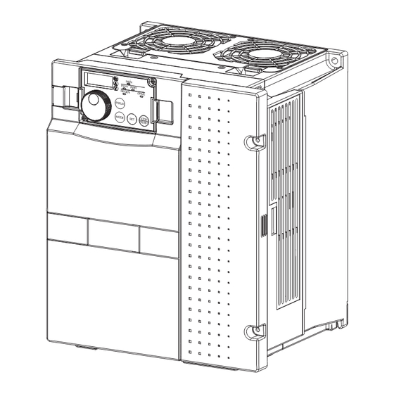
Page 12: Product Checking And Parts Identification
(Refer to the instruction manual of options.) Front cover (Refer to page 16) Combed shaped wiring cover Capacity plate Rating plate Rating plate Capacity plate FR-HC2-7.5K Converter model name FR-HC2-7.5K Converter model name Serial number Applicable inverter capacity Input rating Rated output Serial number... - Page 13 Always install the included peripheral devices. Check the model name of the each peripheral device. For the 400V class peripheral devices, H is indicated in front of the model name. FR-HC2-7.5K to 75K, FR-HC2-H7.5K to H220K Peripheral Device Description...
-
Page 14: Converter And Peripheral Devices
Converter and peripheral devices Converter and peripheral devices Three-phase AC power supply Use within the permissible power supply specifications of the converter. Moulded case circuit breaker (MCCB) or earth leakage current breaker (ELB), fuse The breaker must be selected carefully since an inrush current flows in the converter at power ON. -
Page 15: Precautions For Selecting Peripheral Devices
Precautions for selecting peripheral devices Precautions for selecting peripheral devices 1.3.1 Measures against noises (EMI) In this section, noises indicate those of more than 40th to 50th high frequencies in a power distribution system, which generally assume irregular conditions. Some noises enter the converter to adversely affect it, and others are radiated by the converter to adversely affect peripheral devices. -
Page 16: Emc Measures
Precautions for selecting peripheral devices Noise Measures Transmission Path When the devices, which handle low-level signals and are susceptible to noises (such as measuring instruments, receivers and sensors), are installed near or in the same enclosure with the converter, or their signal cables are placed near of in the same enclosure with the converter, the devices may malfunction due to air-propagated electromagnetic noises. - Page 17 Precautions for selecting peripheral devices (4) Using options to suppress noises By using the radio noise filter (FR-BIF) and the line noise filter (FR-BLF), the noise radiated from the connection cable can be suppressed. Refer to the Instruction Manual of each option for the detail of the radio noise filter (FR-BIF) and the line noise filter (FR-BLF).
-
Page 18: Peripheral Device List
Check the model of the converter and select peripheral devices according to the capacity. Refer to the table below to prepare appropriate peripheral devices. 200V class Moulded Case Circuit Breaker (MCCB) Magnetic Contactor Converter Model or Earth Leakage Circuit Breaker (ELB) (MC) (NF, NV type) FR-HC2-7.5K S-N25 FR-HC2-15K S-N50 FR-HC2-30K 150A S-N80 FR-HC2-55K 300A S-N180 FR-HC2-75K 350A S-N300 400V class... - Page 19 Precautions for selecting peripheral devices (2) Fuse Installation of a fuse is recommended between a high power factor converter and an inverter. Select a fuse according to the capacity of the connected motor. When using a motor, of which the capacity is smaller than the inverter capacity by two ranks or more, select the fuse with the capacity that is one rank lower than the inverter capacity.
- Page 20 Precautions for selecting peripheral devices 400V class Motor Recommended fuse Fuse rating (A) Model Fuse holder (2 poles) capacity (kW) 12.5 6.900 CP GR 10.38 0012.5 0.75 6.900 CP GR 10.38 0016 US102 (without fuse light melting indicator) 6.900 CP GR 10.38 0016 or US102I (with fuse light melting indicator) 6.900 CP GR 10.38 0020...
-
Page 21: Selecting The Rated Sensitivity Current For The Earth Leakage Circuit Breaker
Precautions for selecting peripheral devices 1.3.3 Selecting the rated sensitivity current for the earth leakage circuit breaker When using the earth leakage circuit breaker with the inverter circuit, select its rated sensitivity current as follows. Breaker for harmonic and surge lg1, lg2, lg3 : leakage current of cable path during ... -
Page 22: Installation And Wiring
Protruding the heatsink..............21 Installation of peripheral devices ..........23 Main circuit terminal specifications ..........27 Wiring of main circuit (FR-HC2-7.5K to 75K, FR-HC2-H7.5K to H220K).................... 34 Wiring of main circuit (FR-HC2-H280K) ........41 Wiring of main circuit (FR-HC2-H400K, H560K) ......47 2.10 Notes on earthing (grounding) ............ -
Page 23: Removal And Installation Of The Converter (Fr-Hc2)
Removal and installation of the converter (FR-HC2) front cover Removal and installation of the converter (FR-HC2) front cover Removal of the operation panel 2) Push the left and right hooks of the operation panel and pull 1) Loosen the two fixed screws on the operation panel. the operation panel toward you to remove. - Page 24 Removal and installation of the converter (FR-HC2) front cover 30K or higher Removal 1) Loosen the installation screws of 2) Loosen the installation screw of 3) Push the two installation hooks on the right to the front cover 1, and remove the the front cover 2.
-
Page 25: Removal And Installation Of The Outside Box (Fr-Hcb2) Front
Removal and installation of the outside box (FR-HCB2) front cover Removal and installation of the outside box (FR-HCB2) front cover Removal 1) Loosen the installation screws of the front cover. 2) For removal, pull off the front cover. Front cover Front cover Reinstallation 1) Securely press the front cover... -
Page 26: Installation
Installation Installation Incorrect installation and connection may cause the equipment to operate improperly and its lifespan to be reduced considerably. Please handle the unit properly in accordance with the information on each section as well as the precautions in this manual. 2.3.1 Converter placement Installation of the converter... - Page 27 Installation (2) Clearances around the converter To ensure ease of heat radiation and maintenance, leave at least the shown clearance around the converter. At least the following clearance are required under the converter as a wiring space, and above the converter as a heat radiation space. Surrounding air temperature and humidity Clearance (front) Clearance (side)
-
Page 28: Protruding The Heatsink
When using a heatsink protrusion attachment (FR-A7CN) For the FR-HC2-7.5K to 75K and FR-HC2-H7.5K to H110K, a heatsink can be protruded outside the enclosure using a heatsink protrusion attachment (FR-A7CN). (For the 160K or higher, the attachment is not necessary when the heatsink is to be protruded.) - Page 29 Protruding the heatsink (2) Moving and removing the back installation frames FR-HC2-H160K to H280K Shift Upper One installation frame is attached to each of the upper and lower parts installation frame of the converter. Change the position of the rear side installation frame on the upper and lower sides of the converter to the front side as shown on the right.
-
Page 30: Installation Of Peripheral Devices
Installation of peripheral devices Installation of peripheral devices 2.5.1 Installation of reactor 1 and reactor 2 Model name confirmation Take caution as the appearances of the reactor 1 (FR-HCL21) and the reactor 2 (FR-HCL22) are very similar. Reactor 1(FR-HCL21) AC REACTOR MODEL FR-HCL21-XXX SERIAL XXXXX... -
Page 31: Installation Of The Outside Box (Fr-Hcb2-7.5K To 75K, Fr-Hcb2-H7.5K To H220K)
Installation of peripheral devices (5) Installation orientation To prevent looseness, install the reactor 1 (FR-HCL21) and the reactor 2 (FR-HCL22) on a horizontal surface securely with screws or bolts. Do not install them on a vertical wall. Install them on a mounting stand which can withstand their weight. NOTE Since the charged sections of the reactor 1 and the reactor 2 are uncovered, fully protect them to prevent ground fault and electric shock. -
Page 32: Installation Of Filter Capacitor (Fr-Hcc2-H280K To H560K)
Installation of peripheral devices 2.5.3 Installation of filter capacitor (FR-HCC2-H280K to H560K) Clearance Because the filter capacitor (FR-HCC2) generates heat, leave sufficient space around it. 10cm or more 10cm or more 10cm or more Installation place Install the filter capacitor on nonflammable material. Direct installation on a flammable material will cause a fire. Environment Avoid places where the equipment is subjected to oil mist, flammable gases, fluff, dust, dirt, etc. -
Page 33: Installation Of Mc Power Supply Stepdown Transformer (Fr-Hcm2-H280K To H560K)
Installation of peripheral devices (3) Environment Avoid places where the equipment is subjected to oil mist, flammable gases, fluff, dust, dirt, etc. Install the equipment in a clean place or protect it from suspended substances. Do not place a flammable material near the equipment. (4) Installation orientation To prevent looseness, install the inrush current limit resistor (FR-HCR2) on a horizontal or vertical surface securely with screws or bolts. -
Page 34: Main Circuit Terminal Specifications
Main circuit terminal specifications Main circuit terminal specifications 2.6.1 Description of main circuit terminal Terminal Terminal Name Description Symbol These terminals are used to detect power phase and power voltage, and to input control R/L1, S/L2, T/L3 Power input power. Connect them to the commercial power supply. If the inverter is operated without connecting them to the commercial power supply, the converter will be damaged. -
Page 35: Terminal Arrangement Of The Main Circuit Terminal
Main circuit terminal specifications 2.6.2 Terminal arrangement of the main circuit terminal 200V class FR-HC2-7.5K FR-HC2-15K Charge lamp Screw size (M4) R1/L11 S1/L21 Charge lamp Screw size (M6) ∗ ∗ R1/L11 S1/L21 R/L1 S/L2 T/L3 Screw size (M5) R/L1 S/L2 T/L3... - Page 36 Main circuit terminal specifications 400V class FR-HC2-H7.5K, H15K FR-HC2-H30K Screw size (M4) R1/L11 S1/L21 Charge lamp Charge lamp Screw size R1/L11 S1/L21 (M4) Screw size (M5) Screw size (M6) Screw size (M4) R/L1 S/L2 T/L3 Screw Screw size size (M6) (M6) Screw size...
- Page 37 Main circuit terminal specifications FR-HC2-H110K FR-HC2-H160K, H220K Screw size (M4) Screw size (M4) R1/L11 S1/L21 R1/L11 S1/L21 Charge lamp Charge lamp Screw size Screw size Screw size (M4) (M10) (M10) Screw size Screw size (M12) (M4) Screw size (M10) Screw Screw size size...
-
Page 38: Cable Sizes Of The Main Control Circuit Terminals And Earth (Ground) Terminals
P/+, N/- Nm S4/L24, P/+, N/- S4/L24, S4/L24, S4/L24, cable cable T4/L34 T4/L34 T4/L34 T4/L34 FR-HC2-7.5K 5.5-5 FR-HC2-15K 22-6 14-6 7.8/14.7 FR-HC2-30K 60-8 38-10 (4.4) M10(M6) FR-HC2-55K M12(M6) 24.5 (4.4) 100-12 100-12 FR-HC2-75K M12(M10) 24.5 (14.7) - Page 39 Main circuit terminal specifications 400V class (when input power supply is 440V) <Converter (FR-HC2)> Crimping Cable Size Tightening AWG/MCM Terminal Terminal HIV, etc.(mm PVC, etc.(mm Model Name Torque R4/L14, R4/L14, R4/L14, R4/L14, Screw Size Earthing Earthing P/+, N/- P/+, N/- P/+, N/-...
- Page 40 Main circuit terminal specifications <Reactor2 (FR-HCL22)> Cable Size Crimping Tightening AWG/MCM Terminal Terminal HIV, etc.(mm PVC, etc.(mm Model Name Torque Screw Size R3/L13,S3/L23,T3/L33 R3/L13,S3/L23,T3/L33 R3/L13,S3/L23,T3/L33 R3/L13,S3/L23,T3/L33 Nm R4/L14,S4/L24,T4/L34 R4/L14,S4/L24,T4/L34 R4/L14,S4/L24,T4/L34 R4/L14,S4/L24,T4/L34 FR-HCL22-H7.5K 5.5-4 FR-HCL22-H15K 5.5-5 FR-HCL22-H30K 22-6 FR-HCL22-H55K 60-8 FR-HCL22-H75K...
-
Page 41: Wiring Of Main Circuit (Fr-Hc2-7.5K To 75K, Fr-Hc2-H7.5K To H220K)
Wiring of main circuit (FR-HC2-7.5K to 75K, FR-HC2-H7.5K to H220K) Wiring of main circuit (FR-HC2-7.5K to 75K, FR-HC2-H7.5K to H220K) Perform wiring securely to conform with the harmonic suppression guideline of the former Ministry of International Trade and Industry (currently the Japanese Ministry of Economy, Trade and Industry). Incorrect wiring causes the converter to display an alarm or causes an fault or damage. -
Page 42: Wiring Of Main Circuit
Wiring of main circuit (FR-HC2-7.5K to 75K, FR-HC2-H7.5K to H220K) NOTE • When connecting the converter to the inverter, match the control logic (sink logic (initial setting)/source logic). The converter does not operate properly if the control logic is different. - Page 43 Wiring of main circuit (FR-HC2-7.5K to 75K, FR-HC2-H7.5K to H220K) (2) Wiring of reactor 1 and outside box • Cable size differs by the capacity. Select an appropriate cable by referring to 2.6.3 Cable sizes of the main control circuit terminals and earth (ground) terminals (refer to page 31) and perform wiring.
- Page 44 Wiring of main circuit (FR-HC2-7.5K to 75K, FR-HC2-H7.5K to H220K) Wiring of outside box and reactor 2 • Cable size differs by capacity. Select an appropriate cable by referring to 2.6.3 Cable sizes of the main control circuit terminals and earth (ground) terminals (refer to page 31) and perform wiring.
- Page 45 Wiring of main circuit (FR-HC2-7.5K to 75K, FR-HC2-H7.5K to H220K) (5) Wiring of high power factor converter and inverter • These units should be connected to transmit commands from the high power factor converter to the inverter securely. Connection method differs depending on the inverter series. Refer to the Instruction Manual of the inverter when connecting.
- Page 46 Wiring of main circuit (FR-HC2-7.5K to 75K, FR-HC2-H7.5K to H220K) Wiring reactor 1 and converter Supply power to the power detecting terminals (R/L1, S/L2, T/L3) separately from the main circuit wiring. <Wiring example of 7.5K> Converter Reactor 1 Reactor 1...
- Page 47 Wiring of main circuit (FR-HC2-7.5K to 75K, FR-HC2-H7.5K to H220K) (8) Wiring of outside box and high power factor converter Use the cable shown in the below table for the connection. Cable gauge 0.75 to 1.25mm Converter terminals ROH and SD are used for the control signal for the inrush current limit circuit inside the outside box.
-
Page 48: Wiring Of Main Circuit (Fr-Hc2-H280K)
Wiring of main circuit (FR-HC2-H280K) Wiring of main circuit (FR-HC2-H280K) Perform wiring securely to conform with the harmonic suppression guideline of the former Ministry of International Trade and Industry (currently the Japanese Ministry of Economy, Trade and Industry). Incorrect wiring causes the converter to display an alarm or causes an fault or damage. - Page 49 Wiring of main circuit (FR-HC2-H280K) NOTE • When connecting the converter to the inverter, match the control logic (sink logic (initial setting)/source logic). The converter does not operate properly if the control logic is different. (Refer to page 60 for the switching of the control logic. Refer to the Instruction Manual of the inverter for the switching of the control logic of the inverter.) •...
-
Page 50: Wiring Of Main Circuit
Wiring of main circuit (FR-HC2-H280K) 2.8.2 Wiring of main circuit Wiring power supply and reactor 1 Use the cable shown in the below table for the connection. Cable gauge 200mm Use the moulded case circuit breaker (MCCB), the earth leakage circuit breaker (ELB) or the magnetic contactor (MC) shown in the below table. - Page 51 Wiring of main circuit (FR-HC2-H280K) 1) Filter capacitor Install three filter capacitors in parallel to the output side of the reactor 1 or to the input side of the inrush current limit MC as shown in the above diagram. Use the cable shown in the table below for the connection of filter capacitor. Cable gauge 60mm Wiring length...
- Page 52 Wiring of main circuit (FR-HC2-H280K) Wiring example of converter and inverter These units should be connected to transmit commands from the converter to the inverter securely. Connection method differs depending on the inverter series. Refer to the Instruction Manual of the inverter when connecting.
- Page 53 Wiring of main circuit (FR-HC2-H280K) (6) Wiring the power supply and inverter Connect the inverter control power supply directly to the power supply without connecting a converter in between. R1/L11 Inverter control S1/L21 power supply MCCB Power supply Cable gauge 0.75 to 2mm NOTE ...
-
Page 54: Wiring Of Main Circuit (Fr-Hc2-H400K, H560K)
Wiring of main circuit (FR-HC2-H400K, H560K) Wiring of main circuit (FR-HC2-H400K, H560K) Perform wiring securely to conform with the harmonic suppression guideline of the former Ministry of International Trade and Industry (currently the Japanese Ministry of Economy, Trade and Industry). Incorrect wiring causes the converter to display an alarm or causes an fault or damage. -
Page 55: Wiring Of Main Circuit
Wiring of main circuit (FR-HC2-H400K, H560K) NOTE • When connecting the converter to the inverter, match the control logic (sink logic (initial setting)/source logic). The converter does not operate properly if the control logic is different. (Refer to page 60 for the switching of the control logic. Refer to the Instruction Manual of the inverter for the switching of the control logic of the inverter.) •... - Page 56 Wiring of main circuit (FR-HC2-H400K, H560K) Wiring reactor 1, filter capacitor, limit resistor, inrush current limit MC, and reactor 2 <Wiring example of 400K> Limit MC1 Reactor 1 Reactor 2 Converter (FR-HCL21-H400K) (FR-HC2-H400K) (FR-HCL22-H400K) To inverter FR-HCC2-H400K FR-HCC2-H400K 1)Filter capacitors 2 Limit MC2 Filter capacitor alarm detector (NC contact) 2 Buffer relay for...
- Page 57 Wiring of main circuit (FR-HC2-H400K, H560K) 1) Filter capacitor Install filter capacitors to the output side of the reactor 1 or to the input side of the inrush current limit MC as shown in the connection diagram on page 49. Connect two units in parallel for 400K, and three units in parallel for 560K.
- Page 58 Wiring of main circuit (FR-HC2-H400K, H560K) Wiring example of converter and inverter These units should be connected to transmit commands from the converter to the inverter securely. Connection method differs depending on the inverter series. Refer to the Instruction Manual of the inverter when connecting.
- Page 59 Wiring of main circuit (FR-HC2-H400K, H560K) (6) Wiring the power supply and inverter Connect the inverter control power supply directly to the power supply without connecting a converter in between. R1/L11 Inverter control S1/L21 power supply MCCB Power supply Cable gauge 0.75 to 2mm NOTE ...
-
Page 60: Notes On Earthing (Grounding)
Notes on earthing (grounding) 2.10 Notes on earthing (grounding) Always earth (ground) the converter with its accessories (reactor 1, reactor 2, outside box, filter capacitor). (1) Purpose of earthing (grounding) Generally, an electrical apparatus has an earth (ground) terminal, which must be connected to the ground before use. An electrical circuit is usually insulated by an insulating material and encased. -
Page 61: 2.11 Compatible Inverter For The High Power Factor Converter
2.2K Inverter capacity 3.7K 5.5K 7.5K 18.5K lower FR-HC2-7.5K — FR-HC2-15K — — — ... -
Page 62: 2.11.2 Inverter Parameter Settings
Compatible inverter for the high power factor converter 2.11.2 Inverter parameter settings When using the converter with the inverter, some inverter parameters must be set. The parameter settings differ by the inverter series. For the parameters and inverters not listed below, refer to the Instruction Manual of the inverter. V/F control Other than V/F control Inverter series... -
Page 63: 2.12 Wiring Of Several Inverters To One Converter
Wiring of several inverters to one converter 2.12 Wiring of several inverters to one converter Up to ten inverters can be connected to one converter. Be sure to use a converter with the capacity higher than the total capacities of inverters. Additionally, the total capacity of the inverters needs to be higher than half the converter capacity. If the total inverter capacity is less than half the converter capacity, the converter can be used as a common converter or a regenerative converter. - Page 64 Wiring of several inverters to one converter Example of control circuit wiring INV1 FR-HC2 A720 INV2 A720 INV3 For the control circuit wiring, use shielded or twisted A720 5.5K wires, and separate the wire from the main circuit and high-voltage circuits. Keep the total wiring length within 30m.
-
Page 65: 2.13 Wiring Of Control Circuit
Wiring of control circuit 2.13 Wiring of control circuit 2.13.1 Description of control circuit terminal indicates that terminal functions can be selected using Pr. 3 to Pr. 7 (input terminal function selection) and Pr. 11 to Pr. 16 (output terminal function selection)(Refer to page 76, 78) (1) Input signal Terminal Type... - Page 66 Wiring of control circuit Output signal Terminal Type Terminal Name Description Rated Specifications Symbol Turns ON at alarm occurrence and reset (RES) signal input. Connect this terminal to the terminal MRS or a terminal where Inverter run enable the X10 signal is assigned to in the inverter. signal Turning ON RDY signal stops the inverter.
-
Page 67: 2.13.2 Changing The Control Logic
Wiring of control circuit 2.13.2 Changing the control logic The input signals are set to sink logic (SINK) when shipped from the factory. To change the control logic, the jumper connector on the back of the control terminal must be moved to the other position. (The output signals may be used in either the sink or source logic independently of the jumper connector position.) (1) Loosen the two installation screws at the both side of the control circuit terminal block. - Page 68 Wiring of control circuit (4) Sink logic and source logic In the sink logic, a signal switches ON when a current flows from the corresponding signal input terminal. Terminal SD is common to the contact input signals. Terminal SE is common to the open collector output signals. In the source logic, a signal switches ON when a current flows into the corresponding signal input terminal.
-
Page 69: 2.13.3 Control Circuit Terminal Layout
Wiring of control circuit 2.13.3 Control circuit terminal layout Dedicated board for FR-HC2 Terminal screw size: M3 Terminals 5, IRH, IRL, TR1, TR2, IRO, MCO, RDO, RDI, and MCI are for manufacturer setting. Keep them open. 88R 88S NC AM M3.5 Terminal screw size: (1) Common terminals of the control circuit (SD, 5, SE, SE2) -
Page 70: 2.13.4 Wiring Instructions
Wiring of control circuit Signal inputs by contactless switches The contacted input terminals of the converter (RES, SOF, X1, X2, ROH) +24V can be controlled using a transistor instead of a contacted switch as shown on the right. RES, etc Converter External signal input using transistor 2.13.4 Wiring instructions... -
Page 71: 2.13.5 When Connecting The Operation Panel Or Parameter Unit Using A Connection Cable
Wiring of control circuit 2.13.5 When connecting the operation panel or parameter unit using a connection cable Having an operation panel on the enclosure surface is convenient. With a connection cable, you can mount the operation panel (FR-DU07-CNV) or parameter unit (FR-PU07) to the enclosure surface, and connect it to the converter. Use the option FR-CB2, or the following connector and cable available on the market. -
Page 72: Parameters
PARAMETERS This chapter provides the "PARAMETERS" of this product. Always read the instructions before using the equipment. Operation panel (FR-DU07-CNV) ..........66 Parameter unit (FR-PU07), parameter unit with battery pack (FR-PU07BB(-L))................69 Parameter list ................73 Description of parameters ............75 Parameter clear / All parameter clear.......... -
Page 73: Operation Panel (Fr-Du07-Cnv)
Operation panel (FR-DU07-CNV) Operation panel (FR-DU07-CNV) 3.1.1 Names and functions of the operation panel (FR-DU07-CNV) Operation mode indicator P.CPY: Flickers at the completion of parameter copy. OFF at converter reset. PWR : Lit at power ON Power / regenerative drive indicator DRIVE: Lit during power driving REGEN: Lit during regenerative driving (DRIVE or REGEN flickers when a stop is... -
Page 74: Basic Operation (Factory Setting)
Operation panel (FR-DU07-CNV) 3.1.2 Basic operation (factory setting) Monitor mode (Input current monitor) Input voltage monitor Bus voltage monitor Display the present Parameter setting mode setting (Example) Value change Parameter and a setting value flicker alternately. Parameter write is completed!! Parameter clear All parameter Faults clear... -
Page 75: Changing The Parameter Setting Value
Operation panel (FR-DU07-CNV) 3.1.3 Changing the parameter setting value Changing example Change the Pr. 3 ROH terminal function selection setting. Operation Display Screen at power-ON The monitor display appears. The parameter Press to choose the parameter number read setting mode. previously appears. -
Page 76: Parameter Unit (Fr-Pu07), Parameter Unit With Battery Pack (Fr-Pu07Bb(-L))
Parameter unit (FR-PU07), parameter unit with battery pack (FR-PU07BB(-L)) Parameter unit (FR-PU07), parameter unit with battery pack (FR-PU07BB(-L)) Parameter setting and monitor display can be performed by connecting the parameter unit (FR-PU07) or the parameter unit with battery pack (FR-PU07BB(-L)) to the converter. Note that their functions are limited compared to when they are used with the inverter. -
Page 77: Monitoring Function
Parameter unit (FR-PU07), parameter unit with battery pack (FR-PU07BB(-L)) 3.2.3 Monitoring function (1) Monitor display overview (f) Warning indication I In 10.0 (a) Main monitor (e) Unit indication (b) Connection phase sequence indication (d) Operation mode indication (c) Operating status indication a) Main monitor Shows the input frequency, input current, bus voltage, fault history and other monitor data. -
Page 78: Function Menu
Parameter unit (FR-PU07), parameter unit with battery pack (FR-PU07BB(-L)) 3.2.4 Function menu Press in any operation mode to call the function menu, on which you can perform various functions. REMARKS Some menus are not available. Function menu list Function menu Description 1. - Page 79 Parameter unit (FR-PU07), parameter unit with battery pack (FR-PU07BB(-L)) 3 Pr.List 1 Setting Mode SETTING MODE 1 Appl.Grp 0~9:Ser Pr.No. 2 Pr.List 2 Pr.List 3 Set Pr.List 3 User List Select Oper 4 Param Copy 4 Def.Pr.List Pr Mode Max.F Min.F 3 Pr.List ROH Sel...
-
Page 80: Parameter List
Parameter list Parameter list REMARKS indicates simple mode parameters. The parameters shaded in allow their settings to be changed during operation even if "1" (write disabled) is set to Pr. 77 Parameter write selection. Initial Refer to Customer Parameter Name Range Increments... - Page 81 Parameter list Initial Refer to Customer Parameter Name Range Increments value page setting Rated 0.01A/ 56 Current monitoring reference 0 to 500A/0 to 3600A current 0.1A 57 Restart selection 0, 9999 9999 Free parameter 1 0 to 9999 9999 Free parameter 2 0 to 9999...
-
Page 82: Description Of Parameters
Description of parameters Description of parameters 3.4.1 Displaying and hiding extended parameters (Pr. 0) Parameter which can be read from the operation panel and parameter unit can be restricted. Parameter Name Initial Value Setting Range Description Number Only the simple mode parameters can be 9999 displayed. -
Page 83: Input Terminal Function Selection (Pr. 3 To Pr. 7)
Description of parameters 3.4.3 Input terminal function selection (Pr. 3 to Pr. 7) Use the following parameters to select/change the input terminal functions. Parameter Initial Setting Name Initial Signal Number Value Range ROH terminal function selection ROH (ROH inrush resistance overheat detection) SOF terminal function selection SOF (converter stop) X1 terminal function selection... -
Page 84: Operation Selection Of Sof Signal And Oh Signal (Pr. 8, Pr. 9)
Description of parameters 3.4.4 Operation selection of SOF signal and OH signal (Pr. 8, Pr. 9) Operation of SOF signal can be changed by the Pr. 8 setting, and OH signal by the Pr. 9 setting. Parameter Initial Setting Name Description Number Value... -
Page 85: Output Terminal Function Selection (Pr. 10 To Pr. 16)
Description of parameters 3.4.5 Output terminal function selection (Pr. 10 to Pr. 16) Use the following parameters to change the functions of the open collector output terminals and relay output terminal. Parameter Initial Name Initial Signal Setting Range Number Value RDY signal logic selection RDY (Inverter run enable signal) 0, 100... -
Page 86: Dc Voltage Control (Pr. 22 To Pr. 24, Pr. 80, Pr. 81)
Description of parameters 3.4.6 DC voltage control (Pr. 22 to Pr. 24, Pr. 80, Pr. 81) DC voltage of the converter can be controlled to be as commanded. Operation should be stable in the initial setting, but adjust the following parameters when voltage fluctuation occurs due to the environment such as a voltage condition. -
Page 87: Input Current Detection Function (Y12 Signal, Y13 Signal, Pr. 25 To Pr. 30)
Description of parameters 3.4.7 Input current detection function (Y12 signal, Y13 signal, Pr. 25 to Pr. 30) The input current during converter running can be detected and output to the output terminal. Parameter Initial Name Setting Range Description Number Value Set the input current detection level. -
Page 88: Displaying The Life Of The Converter Parts (Pr. 31 To Pr. 33)
Description of parameters 3.4.8 Displaying the life of the converter parts (Pr. 31 to Pr. 33) Degrees of deterioration of control circuit capacitor, cooling fan and inrush current limit circuit can be diagnosed by the monitor. When any part has approached the end of its life, an alarm can be output by self diagnosis to prevent a fault. (Use the life check of this function as a guideline since the life is calculated theoretically.) Parameter Setting... -
Page 89: Maintenance Timer Alarm (Pr. 34, Pr. 35)
Description of parameters (2) Life display of the inrush current limit circuit (Pr. 32) The life of the inrush current limit circuit (relay, contactor and inrush resistor) is displayed in Pr. 32. The number of contact (relay, contactor, thyristor) ON times is counted, and it is counted down from 100% (0 time) every 1%/1,000 times. -
Page 90: Cooling Fan Operation Selection (Pr. 36)
Description of parameters 3.4.10 Cooling fan operation selection (Pr. 36) Cooling fans built into the converter can be controlled. Parameter Initial Setting Name Description Number Value Range A cooling fan operates at power ON. Cooling fan ON/OFF control is invalid. (The cooling fan is always ON at power ON) Cooling fan operation selection Cooling fan ON/OFF control is valid. -
Page 91: Reference Of The Terminal Fm (Pulse Train Output) And Terminal Am (Analog Output) (Pr. 45, Pr. 49, Pr. 51, Pr. 53, Pr. 55, Pr. 56)
Description of parameters 3.4.12 Reference of the terminal FM (pulse train output) and terminal AM (analog output) (Pr. 45, Pr. 49, Pr. 51, Pr. 53, Pr. 55, Pr. 56) Two types of monitor output, pulse train output from the terminal FM and analog voltage output from the terminal AM, are available. - Page 92 Description of parameters Reference for input power monitor (Pr. 51), input voltage monitor (Pr. 53), bus voltage monitor (Pr. 55), and current monitor (Pr. 56). For the calibration of terminal FM, set the full-scale value of the connected meter when the pulse speed of terminal FM is 1440 pulse/s.
-
Page 93: Du/Pu, Terminal Fm/Am Monitor Display Selection (Pr. 46 To Pr. 48, Pr. 50, Pr. 52, Pr. 54)
Description of parameters 3.4.13 DU/PU, terminal FM/AM monitor display selection (Pr. 46 to Pr. 48, Pr. 50, Pr. 52, Pr. 54) The monitor to be displayed on the main screen of the operation panel (FR-DU07-CNV)/parameter unit (FR-PU07) can be selected. In addition, signals to be output from the terminal FM (pulse train output) and AM (analog voltage output) can be selected. - Page 94 Description of parameters Pr. 52 Setting Full-scale Pr. 54 (FM) Value of the Types of Monitor Increments Pr. 50 (AM) Description Terminal FM DU LED main Setting and AM monitor Depends on Depends on Monitoring item is changed by ON/OFF of Switching by input terminal 1111 to 4444 the monitor...
- Page 95 Description of parameters (3) Cumulative power monitor and clear (Pr. 46, Pr. 48) On the cumulative power monitor (Pr. 52 = "8"), the input power is accumulated and updated in 100ms increments. (The value is stored in EEPROM every 1h.) ...
-
Page 96: Operation Selection At Instantaneous Power Failure (Pr. 57)
Description of parameters Monitor switching with input terminal (Pr. 50, Pr. 52, Pr. 54) Monitoring item can be switched by ON/OFF of terminals X1 and X2. By setting 1 to 4 to the four digits of Pr. 52 (Pr. 54, Pr. 50), monitor can be switched by the terminals. Number set in each digits represents the following monitor. -
Page 97: Free Parameter (Pr. 58, Pr. 59)
Description of parameters 3.4.15 Free parameter (Pr. 58, Pr. 59) You can input any number within the setting range of 0 to 9999. For example, the number can be used: As a unit number when multiple units are used. ... -
Page 98: Retry Function (Pr. 65, Pr. 67 To Pr. 69)
Description of parameters 3.4.17 Retry function (Pr. 65, Pr. 67 to Pr. 69) If a fault occurs, the converter resets itself automatically to restart. Fault-activating retries can be also selected. Parameter Name Initial value Setting range Description Number A fault for retry can be selected. (Refer to the Retry selection 0 to 4 table in the next page.) -
Page 99: Reset Selection/Disconnected Pu Detection/Pu Stop Selection (Pr. 75)
Description of parameters Using Pr. 65, you can select the fault that will cause a retry. No retry will be made for the fault not indicated. (Refer to page 126 for the fault description. ) indicates the faults selected for retry. Fault for Pr. - Page 100 Description of parameters Reset selection You can select the enable condition of reset function (RES signal, reset command through communication) input. When Pr. 75 is set to any of "1, 3, 15, 17", a reset can be input only when the converter is tripped. NOTE ...
-
Page 101: Parameter Write Disable Selection (Pr. 77)
Description of parameters 3.4.19 Parameter write disable selection (Pr. 77) You can select whether to enable the writing to various parameters or not. Use this function to prevent parameter values from being rewritten by misoperation. Parameter Name Initial Value Setting Range Description Number Parameter write is disabled. -
Page 102: Current Control (Pr. 82, Pr. 83)
Description of parameters 3.4.20 Current control (Pr. 82, Pr. 83) This function controls current to be as commanded. Operation should be stable in the initial setting, but adjust the following parameters when current fluctuation occurs due to the environment such as power source condition. Parameter Initial Name... -
Page 103: System Configuration
Description of parameters (2) Wiring and configuration of PU connector communication system System configuration Station 0 Computer Station 0 Computer Converter Converter Converter RS-232C FR-DU07-CNV Operation connector panel RS-485 RS-232C Maximum connector connector connector connector interface/ cable FR-ADP terminals RS-232C-RS-485 (option) converter... -
Page 104: Initial Settings And Specifications Of Rs-485 Communication (Pr. 117 To Pr. 124)
Description of parameters 3.4.22 Initial settings and specifications of RS-485 communication (Pr. 117 to Pr. 124) This function is used to perform required settings for RS-485 communication between the converter and personal computer. Use PU connector of the converter for communication. You can perform parameter setting, monitoring, etc. -
Page 105: Mitsubishi Inverter Protocol (Computer Link Communication)
Description of parameters 3.4.23 Mitsubishi inverter protocol (computer link communication) You can perform parameter setting, monitoring, etc. from the PU connector of the converter using the Mitsubishi inverter protocol (computer link communication). (1) Communication The communication specifications are given below. Related Item Description... - Page 106 Description of parameters Communication operation presence/absence and data format types Data communication between the computer and converter is made in ASCII code (hexadecimal code). Communication operation presence/absence and data format types are as follows. Parameter/ Converter Parameter Operation Monitor Monitor Reset...
- Page 107 Description of parameters Data reading format Communication request data from the computer to the converter 1) Number of Characters Format Station number Instruction code check Reply data from the converter to the computer 3) (No data error detected) Number of Characters Format Station number...
- Page 108 Description of parameters Data definitions 1) Control code Signal ASCII Code Description Name Start Of Text (Start of data) End Of Text (End of data) Enquiry (Communication request) Acknowledge (No data error detected) Line Feed Carriage Return Negative Acknowledge (Data error detected) 2) Station number Specify the station number of the converter which communicates with the computer.
- Page 109 Description of parameters 7) Error code If any error is found in the data received by the converter, its error definition is sent back to the computer together with the NAK code. Error Error Item Error Description Converter Operation Code The number of errors consecutively detected in communication Computer NAK error request data from the computer is greater than permissible...
- Page 110 Description of parameters Retry count setting (Pr. 121) Set the permissible number of retries at data receive error occurrence. (Refer to page 102 for data receive error for retry.) If data receive errors occur consecutively and exceed the permissible number of retries set, the converter outputs the alarm (LF).
- Page 111 Description of parameters (7) Instructions for the program 1) When data from the computer has any error, the converter does not accept that data. Hence, in the user program, always insert a retry program for data error. 2) All data communication, e.g. run command or monitoring, are started when the computer gives a communication request.
- Page 112 Description of parameters General flowchart Port open Communication setting Time out setting Send data processing Data setting Sum code calculation Data transmission Receive data waiting Receive data processing Data retrieval Screen display CAUTION Always set the communication check time interval before starting operation to prevent hazardous conditions. Data communication is not started automatically but is made only once when the computer provides a communication request.
- Page 113 Description of parameters (8) Setting items and set data After completion of parameter settings, set the instruction codes and data, then start communication from the computer to allow various types of operation control and monitoring. Number of Read/ Instruction Item Data Description Data Digits Write...
- Page 114 Description of parameters Number of Read/ Instruction Item Data Description Data Digits Write code (Format) All parameters return to the initial settings. Whether to clear communication parameters or not can be selected according to the data. (: Clear, : Not clear) Refer to page 188 for parameter clear, all clear, and communication parameters.
- Page 115 Description of parameters [Special monitor selection No.] Refer to page 86 for details of the monitor description. Data Description Increments Data Description Increments Data Description Increments H01 Input current 0.01A/0.1A 0.01kW/ 0.1kW/ H07 Input power H0A Input power H02 Input voltage 0.1V 0.1kW ...
-
Page 116: Initial Setting And Specification For The Cc-Link Communication Function (Pr. 542 To Pr. 544)
Description of parameters 3.4.24 Initial setting and specification for the CC-Link communication function (Pr. 542 to Pr. 544) Set the station number and baud rate required for the CC-Link communication. Parameter Initial Name Setting range Description Number value Communication station 1 to 64 Set the station number of the converter. - Page 117 Description of parameters (3) CC-Link extended setting (Pr. 544) The functions of the remote register can be extended. Refer to page 110 for the details of the remote I/O signals and the remote registers. Pr. 544 Setting Description CC-Link Ver. 0 (Initial setting) Occupies one station (FR-A5NC compatible) ...
- Page 118 Description of parameters 2)Remote register (For the details, refer to page 113.) I/O signals when one station (FR-A5NC compatible) in the CC-Link Ver.1 is occupied. (Pr. 544 = "0") Description Description Device No. Device No. Upper 8 Bits Lower 8 Bits Upper 8 Bits Lower 8 Bits RWwn...
- Page 119 Description of parameters (5) Details of the remote I/O signals The following device numbers are for the station number 1. For the station number 2 and later, the device numbers are different. (Refer to the manual for the CC-Link master module for the correspondence between device numbers and stations numbers.) Output signals (master module ...
- Page 120 Description of parameters Details of the remote register The following device numbers are for the station number 1. For the station number 2 and later, the device numbers are different. (Refer to the manual for the CC-Link master module for the correspondence between device numbers and station numbers.) Remote register (master module ...
- Page 121 Description of parameters (7) Instruction code definition Operation control and monitoring can be performed through CC-Link communication by setting the following instruction codes and corresponding data after setting parameters. Set instruction codes using the remote register (RWw). (Refer to page 113) Definitions read by instruction codes are stored in the remote register (RWr).
-
Page 122: Operation At A Communication Error (Pr. 500 To Pr. 502)
Description of parameters 3.4.25 Operation at a communication error (Pr. 500 to Pr. 502) Operation at a communication error in the CC-Link communication can be selected. Parameter Setting Name Initial value Description Number range Communication error Set the waiting time for the communication error output 500... -
Page 123: Communication Eeprom Write Selection (Pr. 342)
Description of parameters (3) Converter operation at a communication error (Pr. 502) How the converter operates at a communication line error or an option unit fault can be set. Setting description Operation at an error occurrence Fault description Pr. 502 Setting Converter operation Indication Fault output... -
Page 124: Setting Of The Parameter Unit And Operation Panel (Pr. 145, Pr. 990, Pr. 991)
Description of parameters 3.4.27 Setting of the parameter unit and operation panel (Pr. 145, Pr. 990, Pr. 991) Setting of the operation panel and parameter unit can be changed. Parameter Name Initial Value Setting Range Description Number Japanese English German French PU display language selection Spanish... -
Page 125: Terminal Fm And Am Calibration (Calibration Parameter C0 (Pr. 900), C1 (Pr. 901))
Description of parameters 3.4.28 Terminal FM and AM calibration (calibration parameter C0 (Pr. 900), C1 (Pr. 901)) By using the operation panel or parameter unit, you can calibrate terminal FM and AM to full scale deflection. Parameter Name Initial Value Setting Range Description Number... - Page 126 Description of parameters AM terminal calibration (C1 (Pr. 901)) Converter Terminal AM is initially-set to provide a 10VDC output in the full-scale status of the corresponding monitor item. Calibration parameter C1 (Pr. 901) DC10V allows the output voltage ratios (gains) to be adjusted according to the meter scale.
-
Page 127: Parameter Clear / All Parameter Clear
Parameter clear / All parameter clear Parameter clear / All parameter clear POINT Set "1" to Pr. CL Parameter clear, ALLC All parameter clear to initialize all parameters. (Parameters are not cleared when Pr. 77 Parameter write selection = "1".) ... -
Page 128: Parameter Copy And Parameter Verification
Parameter copy and parameter verification Parameter copy and parameter verification PCPY Setting Description Cancel Copy the source parameters to the operation panel. Write the parameters copied to the operation panel into the destination converter. Verify parameters in the converter and operation panel. (Refer to page 122) REMARKS ... - Page 129 Parameter copy and parameter verification appears... Why? Parameter read error. Perform operation from step 3 again. appears... Why? Parameter write error. Perform operation from step 8 again. flicker alternately Appears when parameters are copied between the converter of or lower and or higher.
-
Page 130: Protective Functions
PROTECTIVE FUNCTIONS This chapter provides the "PROTECTIVE FUNCTIONS" of this product. Always read the instructions before using the equipment. Troubleshooting................124 Reset method of protective function .......... 124 List of fault and alarm indications..........125 Causes and corrective actions ............ 126 Correspondences between digital and actual characters .. -
Page 131: Troubleshooting
Troubleshooting Troubleshooting When a fault occurs in the converter, the protective function activates to trip the converter, and the PU display automatically changes to one of the following fault or alarm indications. If the fault does not correspond to any of the following faults or if you have any other problem, please contact your sales representative. -
Page 132: List Of Fault And Alarm Indications
List of fault and alarm indications List of fault and alarm indications Operation Panel Indication Name Refer to page E- - - Faults history HOLD Operation panel lock Error Parameter write error message rE1 to 4 Copy operation fault Err. Error Overload signal detection PU stop... -
Page 133: Causes And Corrective Actions
Causes and corrective actions Causes and corrective actions (1) Error message A message regarding operational troubles is displayed. The converter continues its operation. Operation Panel HOLD Indication Name Operation panel lock Operation lock is set. Operation other than is invalid. Description (Refer to page 90) Checkpoint... - Page 134 Causes and corrective actions Operation Panel Indication Name Model error Parameter write or parameter verification of the parameter copy function is performed to an invalid model. Description When writing of copied parameters is attempted after reading of copied parameters is interrupted ...
- Page 135 Causes and corrective actions Operation Panel FR-PU07 Indication Name Maintenance signal output Indicates that the cumulative energization time of the converter has reached a given time. Description When the setting of Pr. 35 Maintenance timer alarm output set time is the initial setting (Pr. 35 = "9999"), this warning does not occur.
- Page 136 Causes and corrective actions Operation Panel E.OV2 FR-PU07 Stedy Spd OV Indication Name Overvoltage trip If the converter's internal main circuit DC voltage reaches or exceeds the specified value, the protective Description circuit is activated to stop the converter operation.The circuit may also be activated by a surge voltage produced in the power supply system.
- Page 137 Causes and corrective actions Operation Panel E.ILF FR-PU07 Input phase loss Indication Name Input phase loss Description Converter trips when one phase of the three phase power input is lost. Checkpoint Check for a break in the cable for the three-phase power supply input. ...
- Page 138 Causes and corrective actions Operation Panel E.PE FR-PU07 Corrupt Memry Indication Name Parameter storage device fault (control circuit board) Description Stops the converter operation if a fault occurred in the parameter stored. (EEPROM fault) Checkpoint Check for too many number of parameter write times. Please contact your sales representative.
- Page 139 Causes and corrective actions Operation Panel FR-PU07 Fault 9 Indication Name Input power supply fault 2 When the converter operation is stopped continuously due to the fluctuation of input voltage or input current, Description it is regarded as a power supply fault, and the converter operation and the inverter output are stopped. Checkpoint Check the power source and the wiring.
-
Page 140: Correspondences Between Digital And Actual Characters
Correspondences between digital and actual characters Operation Panel E.13 FR-PU07 Fault 13 Indication Name Internal circuit fault Description Stops the converter operation when an internal circuit fault occurs. Corrective action Please contact your sales representative. NOTE If faults other than the above appear, contact your sales representative. Correspondences between digital and actual characters There are the following correspondences between the actual alphanumeric characters and the digital characters displayed on the operation panel:... -
Page 141: Check And Clear Of The Faults History
Check and clear of the faults history Check and clear of the faults history (1) Check and clear of the faults history Monitor/frequency setting Parameter setting [Operation panel is used [Parameter setting change] for operation] Faults history [Operation for displaying faults history] Eight past faults can be displayed with the setting dial. - Page 142 Check and clear of the faults history Clearing procedure POINT Set Er.CL Fault history clear = "1" to clear the faults history. Display Operation Screen at power-ON The monitor display appears. The parameter Press to choose the parameter number previously setting mode.
-
Page 143: Check First When You Have A Trouble
Check first when you have a trouble Check first when you have a trouble Trouble Checkpoint Check the connection. Check if the wiring is performed correctly. Check if appropriate power supply voltage is applied. Converter does not operate properly. ... -
Page 144: Maintenance And Inspection
MAINTENANCE AND INSPECTION This chapter provides "MAINTENANCE INSPECTION" of this product. Always read the instructions before using the equipment. Inspection items................138 Measurement of main circuit voltages, currents and powers .. 145... -
Page 145: Inspection Items
Inspection items The converter is a static unit mainly consisting of semiconductor devices. Daily inspection must be performed to prevent any fault from occurring due to the adverse effects of the operating environment, such as temperature, humidity, dust, dirt and vibration, changes in the parts with time, service life, and other factors. -
Page 146: Daily And Periodic Inspection List
Inspection items 5.1.3 Daily and periodic inspection list Interval Area of Corrective Action at Customer's Inspection Item Description Periodic Daily Inspection Alarm Occurrence Check Surrounding Check the surrounding air temperature, Improve the environment. environment humidity, dirt, corrosive gas, oil mist, etc. Check alarm location and Check for unusual vibration and noise. -
Page 147: Checking The Converter Module
Inspection items 5.1.4 Checking the converter module <Preparation> (1) Disconnect the external power supply cables (R4/L14, S4/L24, T4/L34, P/+, N/-) (2) Prepare a tester. (Use 100 range.) <Checking method> Change the polarity of the tester alternately at the converter terminals R4/L14, S4/L24, T4/L34, P/+, N/- and check the electric continuity. -
Page 148: Replacement Of Parts
When unusual noise and/or vibration are noticed during inspection, the cooling fan must be replaced immediately. NOTE For parts replacement, contact the nearest Mitsubishi FA center. Removal (FR-HC2-7.5K to 75K, FR-HC2-H7.5K to H110K) 1) Push the hooks from above and remove the fan cover. FR-HC2-7.5K, 15K FR-HC2-30K or higher FR-HC2-H7.5K, H15K... - Page 149 Inspection items Reinstallation (FR-HC2-7.5K to 75K, FR-HC2-H7.5K to H110K) 1)After confirming the orientation of the fan, reinstall the fan so that the arrow on the left of "AIR FLOW" faces up. AIR FLOW <Fan side face> 2)Reconnect the fan connectors.
- Page 150 Inspection items Removal (FR-HC2-H160K or higher) 1) Remove the fan cover. 2) Remove the fan connector, then remove the fan block. 3) Remove the fan fixing screws, then remove the fan. (Make sure to remove the fan cable from the clamp of the fan block beforehand.) Fan fixing screws Fan ∗...
- Page 151 Inspection items (2) Smoothing capacitors A large-capacity aluminum electrolytic capacitor is used for smoothing in the main circuit DC section, and an aluminum electrolytic capacitor is used for stabilizing the control power in the control circuit. Their characteristics are deteriorated by the adverse effects of ripple currents, etc.
-
Page 152: Measurement Of Main Circuit Voltages, Currents And Powers
Measurement of main circuit voltages, currents and powers Measurement of main circuit voltages, currents and powers Measurement method of voltage and current at each section When instruments for commercial frequency are used for measurement, measure the following circuits with the instruments given below. -
Page 153: Insulation Resistance Test Using Megger
Measurement of main circuit voltages, currents and powers Measuring Points and Instruments Remarks Item Measuring Point Measuring Instrument (Reference Measured Value) Across R and S Commercial power supply Power supply voltage Across S and T Moving-iron type AC voltmeter Within permissible AC voltage Across T and R fluctuation (Refer to page 148) Power supply side current... -
Page 154: Specifications
SPECIFICATIONS This chapter provides the "SPECIFICATIONS" of this product. Always read the instructions before using the equipment. Rated specifications ..............148 Common specifications ............... 149 Outline dimensions............... 150... -
Page 155: Rated Specifications
Rated specifications Rated specifications 200V Model name FR-HC2-K Applicable inverter capacity (kW) Rated output capacity (kW) 10.7 19.8 Rated input voltage (V) Three-phase 200V to 220V 50Hz/200V to 230V 60Hz Rated input current (A) Overload current rating 150% 60s ... -
Page 156: Common Specifications
Common specifications Common specifications Control method PWM control Power supply frequency range 50Hz to 60Hz Current limit level Current limit value selectable (0 to 220% variable) The following signals can be assigned to Pr. 3 to Pr. 7 (input terminal function selection): Input signal (Five terminal) converter stop, monitor switching, converter reset, external thermal relay, and inrush resistance overheat detection. -
Page 157: Outline Dimensions
Outline dimensions Outline dimensions 6.3.1 Converter (FR-HC2) (1) 200V class FR-HC2-7.5K 2-φ6 hole P.CPY PWR REGEN ..DRIVE PSCLR Rating plate (Unit: mm) Mass: 7kg FR-HC2-15K 2-φ10 hole P.CPY PWR REGEN DRIVE PSCLR 10.5 Rating plate (Unit: mm) Mass: 12kg... - Page 158 Outline dimensions FR-HC2-30K 2-φ10 hole 2-φ20 hole (102) Eybolt: 2-M8∗ P.CPY PWR REGEN ..DRIVE PSCLR Rating plate The eyebolt is enclosed with the product. Use it as required. (Unit: mm) Mass: 24kg FR-HC2-55K 2-φ20 hole 2-φ10 hole (150) Eybolt: 2-M8∗...
- Page 159 Outline dimensions FR-HC2-75K 2-φ25 hole 2-φ12 hole (93) 2-φ25 hole Eyebolt : 2-M10∗ P.CPY PWR REGEN DRIVE PSCLR Rating plate The eyebolt is enclosed with the product. Use it as required. (Unit: mm) Mass: 53kg (2) 400V class FR-HC2-H7.5K, H15K 2-φ6 hole Rating plate (Unit: mm)
- Page 160 Outline dimensions FR-HC2-H30K 2-φ10 hole 2-φ20 hole (102) Eyebolt: 2-M8∗ Rating plate The eyebolt is enclosed with the product. Use it as required. (Unit: mm) Mass: 26kg FR-HC2-H55K 2-φ10 hole 2-φ20 hole (142) Eyebolt: 2-M8∗ Rating plate The eyebolt is enclosed with the product.
- Page 161 Outline dimensions FR-HC2-H75K 2-20 hole 2-10 hole (142) Eyebolt: 2-M8 P.CPY PWR REGEN ..DRIVE PSCLR Rating plate The eyebolt is enclosed with the product. Use it as required. (Unit: mm) Mass: 37kg FR-HC2-H110K φ 25 hole φ 25 hole φ...
- Page 162 Outline dimensions FR-HC2-H160K, H220K 3-φ12 hole P.CPY PWR REGEN ..DRIVE PSCLR 200 49 Rating plate φ 16 hole (Unit: mm) Mass: 120kg FR-HC2-H280K 2- 16 hole 2- 30 hole 3- 12 hole (174) Eyebolt : 2-M12∗ P.CPY PWR REGEN DRIVE PSCLR Rating plate...
- Page 163 Outline dimensions FR-HC2-H400K, H560K 3-φ12 hole 2-φ24 hole (Unit: mm) Mass: 250kg...
-
Page 164: Reactor 1 (Fr-Hcl21)
Outline dimensions 6.3.2 Reactor 1 (FR-HCL21) Check that the capacity of the reactor 1 is same as the capacity of the converter. 200V class FR-HCL21-7.5K, 15K R/L1 S/L2 T/L3 Within D2 Rating plate W1 0.5 -2.5 Varnish removed area (front/rear side) 4-M6 hole Model Mass... - Page 165 Outline dimensions FR-HCL21-55K ∗Enlarged view of section A Rating plate Crimping terminal for 6-M12 screws (80-M12) Within 105 ∗A S/L2 T/L3 R/L1 -2.5 Within 210 (Unit: mm) Within 140 58 2.5 Mass: 17.4kg Varnish removed area (front/rear side) 4-M6 hole FR-HCL21-75K ∗Enlarged ∗Enlarged...
- Page 166 Outline dimensions 400V class FR-HCL21-H7.5K 50 0.5 4-M6 hole -0.5 R/L1 S/L2 T/L3 Within 55 Rating plate (Unit: mm) Mass: 4kg Varnish removed area (front/rear side) FR-HCL21-H15K 4-M6 hole -0.5 R/L1 S/L2 T/L3 Within 65 Rating plate (Unit: mm) Mass: 6kg Varnish removed area (front/rear side)
- Page 167 Outline dimensions FR-HCL21-H30K 75 0.5 4-M6 hole -0.5 R/L1 S/L2 T/L3 Within 95 Rating plate (Unit: mm) 99 2 Mass: 9kg Varnish removed area (front/rear side) FR-HCL21-H55K 8 0.5 4-M6 hole R/L1 S/L2 T/L3 (25) Within 70 Within 95 Varnish removed area (front/rear side) Rating plate (Unit: mm)
- Page 168 Outline dimensions FR-HCL21-H75K ∗Enlarged ∗Enlarged view of view of section A section B Rating plate Approx. 20 75 1 Crimping terminal for 6-M10 screws (60-M10) S/L2 R/L1 T/L3 ∗A Earth (ground) terminal ∗B Approx. 9 (for M8 screw) 75 1 -2.5 (Unit: mm) 127 2...
- Page 169 Outline dimensions FR-HCL21-H160K 4-oval-shaped hole 10 18 for M8 screw Crimping terminal for M12 screws 4 - 20 hole Rating plate T/L3 R/L1 S/L2 R2/L12 S2/L22 T2/L32 176 3 Earth (ground) (Unit: mm) terminal Within 185 Within 280 (for M8 screw) Mass: 45kg FR-HCL21-H220K 4-oval-shaped hole 12 22 for M10 screw...
- Page 170 Outline dimensions FR-HCL21-H280K Rating plate ∗Enlarged ∗Enlarged view of view of section A section B 170 1 Approx. 25 Crimping terminal for 6-M12 screws (200-M12) φ 24 hanging hole. T/L3 S/L2 R/L1 ∗A ∗B 170 1 Earth (ground) terminal 270 2 (Unit: mm) (for M8 screw) 230 2...
- Page 171 Outline dimensions FR-HCL21-H560K 4-M10 eyebolt 350 5 210 5 R, S, T side R2, S2, T2 side 6-terminal 70 5 φ 4- 15 hole for M12 bolt R/L1 R2/L12 S/L2 S2/L22 T/L3 T2/L32 Rating Enlarged plate drawing of Earth (ground) terminal section A (for M8 screw) 300 1...
-
Page 172: Reactor 2 (Fr-Hcl22)
Outline dimensions 6.3.3 Reactor 2 (FR-HCL22) Check that the capacity of the reactor 2 is same as the capacity of the converter. 200V class FR-HCL22-7.5K Varnish removed area (front side) MAX 140 (70) mark 210 1.5 110 1.5 (Unit: mm) 235 2.5 Mass: 9.8kg 4-M6 hole... - Page 173 Outline dimensions FR-HCL22-55K Varnish removed area (front side) MAX 280 430 2.5 (140) mark 270 1.5 240 1.5 (Unit: mm) Mass: 65kg 4-M8 hole FR-HCL22-75K Varnish removed area (front side) MAX 280 (190) mark (Unit: mm) 430 2 130 2 Mass: 98kg 470 4 4-M12 hole...
- Page 174 Outline dimensions 400V class FR-HCL22-H7.5K 210 1.5 8 0.5 4-M6 hole MAX 70 MAX 70 Varnish removed area (front/rear side) (25) Rating plate (Unit: mm) Mass: 9.8kg 129 2.5 235 2.5 FR-HCL22-H15K 230 1.5 8 0.5 4-M6 hole MAX 75 MAX 90 Varnish removed area (front/rear side) (25)
- Page 175 Outline dimensions FR-HCL22-H30K 310 1.5 10 0.5 4-M8 hole MAX 80 MAX 100 Varnish removed area (front/rear side) (30) Rating plate (Unit: mm) Mass: 36kg 153 2.5 340 2.5 FR-HCL22-H55K 360 1.5 10 0.5 4-M8 hole MAX 90 MAX 110 (30) Varnish removed area (front/rear side) Rating...
- Page 176 Outline dimensions FR-HCL22-H75K UL mark (40) Varnish removed area (front side) MAX 280 MAX 430 (160) (Recommended 265 1.5 4-M10 (φ12 0.5) hole installation 200) 200 1.5 (Unit: mm) Mass: 120kg FR-HCL22-H110K UL mark Varnish removed area (front side) (50) MAX 370 (215) MAX 500...
- Page 177 Outline dimensions FR-HCL22-H160K, H220K ULmark (75) Varnish removed area MAX D (front side) MAX D2 (Recommended 400 1.5 4-M12 ( 15 0.5) hole installation D1) MAX W Model Mass FR-HCL22-H160K 250kg FR-HCL22-H220K 345kg (Unit: mm) FR-HCL22-H280K UL mark Varnish removed area MAX 560 (front side) (355)
- Page 178 Outline dimensions FR-HCL22-H400K 4-M12 eyebolt 2- 15 hole 500 5 for M12 screw 300 5 R4, S4, T4 side R3, S3, T3 side 100 5 R3/L13 R4/L14 S3/L23 S4/L24 T3/L33 T4/L34 Earth (ground) terminal (for M8 screw) 400 2 630 2 435 10 Within Within...
-
Page 179: Difference Between The Reactor 1 (Fr-Hcl21) And The Reactor 2 (Fr-Hcl22)
Outline dimensions 6.3.4 Difference between the reactor 1 (FR-HCL21) and the reactor 2 (FR-HCL22). Each reactor has a rating plate. Identify the reactor 1 and the reactor 2 by their rating plates. Incorrect connection order of the reactor 1 and the reactor 2 causes the reactors to heat up, and it is dangerous. Take caution to avoid the danger. [Rating plate] Reactor 1(FR-HCL21) AC REACTOR... - Page 180 Outline dimensions FR-HCB2-30K, 55K 2-A hole Rating plate Type A hole dimensions Model Mass FR-HCB2-30K 11kg FR-HCB2-55K 13kg (Unit: mm) FR-HCB2-75K 4-φ16 hole 3-A hole Rating plate Type A hole dimensions (Unit: mm) Mass: 27kg...
- Page 181 Outline dimensions 400V class FR-HCB2-H7.5K to H30K 2-A hole Rating plate Type A hole dimensions (Unit: mm) Mass: 8kg FR-HCB2-H55K 2-A hole Rating plate Type A hole dimensions (Unit: mm) Mass: 16kg...
- Page 182 Outline dimensions FR-HCB2-H75K 2-A hole Rating plate Type A hole dimensions (Unit: mm) Mass: 16kg FR-HCB2-H110K 3-A hole 4-φ16 hole Rating plate Type A hole dimensions (Unit: mm) Mass: 37kg...
- Page 183 Outline dimensions FR-HCB2-H160K, H220K 4-φ16 hole 3-A hole Rating plate Type A hole dimensions (Unit: mm) Mass: 54kg...
- Page 184 Outline dimensions Terminal block 200V class FR-HCB2-7.5K, 15K FR-HCB2-30K, 55K S2/L22 S2/L22 R2/L12 T2/L32 R2/L12 T2/L32 R3/L13 T3/L33 R3/L13 T3/L33 S3/L23 S3/L23 88R 88S ROH1 ROH2 TB1-1 TB1-2 Earth (ground) terminal ROH1 ROH2 Earth (ground) terminal TB1-2 TB1-1 <Terminal screw size> <Terminal screw size>...
- Page 185 Outline dimensions 400V class FR-HCB2-H7.5K to H30K FR-HCB2-H55K S2/L22 S2/L22 R2/L12 T2/L32 R2/L12 T2/L32 R3/L13 T3/L33 S3/L23 R3/L13 T3/L33 S3/L23 ROH1 ROH2 88R 88S Earth Earth ROH1 ROH2 TB1-2 TB1-1 (ground) (ground) TB1-2 TB1-1 terminal terminal <Terminal screw size> <Terminal screw size> Earth Earth Model...
-
Page 186: Filter Capacitor (Fr-Hcc2)
Outline dimensions FR-HCB2-H160K, H220K T2/L32 R2/L12 S2/L22 TB1-2 TB1-1 ROH1 88R 88S ROH2 Earth S3/L23 T3/L33 (ground) R3/L13 terminal <Terminal screw size> Earth Model TB1-1 TB1-2 (ground) terminal FR-HCB2-H160K, 220K M3.5 M3.5 6.3.6 Filter capacitor (FR-HCC2) FR-HCC2-H280K Enlarged drawing of the installation foot (Recommended bolt size: M12) R7.5 370 3... - Page 187 Outline dimensions FR-HCC2-H400K 400 3 2-15 20 oval-shaped hole M12 screws 365 3 102.5 52.5 90 5 90 5 M12 bolt Enlarged drawing of the installation foot (Recommended bolt size: M12) 370 3 394 3 370 3 Earth (ground) (Unit: mm) 394 3 terminal (M8 bolt) 80 2...
-
Page 188: Fr-Hcm2
Outline dimensions Filter capacitor alarm detector (MDA-1) (FR-HCC2-H400K, H560K) 150 3 Plunger Case Reference value as some margins are taken for the arm Micro switch Screw(M4) Connector Switch terminal and contact symbol of the detector 53 2 15 1 4-M4 5.6 (Unit: mm) 40 2 Screw with toothed... - Page 189 Outline dimensions Contactor (S-N400FXYS AC200V 2A2B) (FR-HCM2-H400K, H560K) (4-M8 hole) M4 screw (self-up) 4-M8 hole (60) (Unit: mm) M12 screw M4 screw (with washer and (self-up) Mass: 9.5kg spring washer) MC power supply stepdown transformer (BKO-CA2001H06) (FR-HCM2-H280K to H560K) Enlarged drawing of installation hole Terminal block for tap switching M4 screw Input side terminal block...
- Page 190 Outline dimensions Terminal block shorting conductor (C152C481H21) (FR-HCM2-H280K) 80 0.4 60 0.4 40 0.4 5-oval 7-8 20 0.3 (2.3) Sectional view of A - A (Unit: mm) Mass: 0.1kg MC shorting conductor (C152C423H21) (FR-HCM2-H400K, H560K) (Unit: mm) 9-M5 screw for installation of Mass: 1.6kg 57.5...
- Page 191 Outline dimensions Mini relay for filter capacitor alarm detector (MYQ4Z AC200/220) (FR-HCM2-H400K, H560K) 21.5 or less φ 1.2 2.2 oval hole 28 or less 28 or less 35.5 or less 21.5 or less (Unit: mm) Mass: 35kg Mini relay terminal block (PYF14T) (FR-HCM2-H400K, H560K) 23.5 33 or lower 11.5...
-
Page 192: Inrush Current Limit Resistor (Fr-Hcr2)
Outline dimensions 6.3.8 Inrush current limit resistor (FR-HCR2) With thermostat (BKO-CA1996H31) (FR-HCR2-H280K to H560K) 2-(17) 215 2 2-500 10 200 1.2 325 15 175 2 2-6 1 2-6 1 Board thickness2.5 (30) (Unit: mm) Mass: 0.8kg Without thermostat (BKO-CA1996H21) (FR-HCR2-H280K to H560K) 2-(17) 215 2 2-500 10... -
Page 193: Parameter Unit
Outline dimensions 6.3.9 Parameter unit Operation panel (FR-DU07-CNV) [Outline drawing] [Enclosure cut dimension drawing] Panel 27.8 FR-DU07-CNV 3.2max Air- bleeding hole Parameter unit connection 2-M3 screw cable(FR-CB2 )(option) Operation panel connection connector (Unit: mm) (FR-ADP option) Parameter unit (option) (FR-PU07) [Outline drawing] [Enclosure cut dimension drawing] 25.05... -
Page 194: Appendices
APPENDICES This chapter provides the "APPENDICES" of this product. Always read the instructions before using the equipment. Appendix 1 Instruction code list............188 Appendix 2 Instructions for compliance with the EU Directives..189 Appendix 3 Instructions for UL and cUL ..........191... -
Page 195: Appendix 1 Instruction Code List
Appendix 1 Instruction code list These instruction codes are used to write or read parameters through the RS-485 communication and the CC-Link communication. (Refer to page 98 for the RS-485 communication. Refer to page 109 for the CC-Link communication.) ... -
Page 196: Appendix 2 Instructions For Compliance With The Eu Directives
CE marking. The authorized representative in the EU The authorized representative in the EU is shown below. Name: Mitsubishi Electric Europe B.V. Address: Gothaer Strasse 8, 40880 Ratingen, Germany Note We declare that this converter, when equipped with the dedicated EMC filter, conforms with the EMC Directive in industrial environments and affix the CE marking on the inverter. - Page 197 Provide the Class T fuse or a fuse with faster shutoff speed, which is UL and cUL listed, for branch circuit protection. Converter model Fuse type Cat. No Manufacturer Rating FR-HC2-7.5K UL Recognized High Speed 170M1414 Bussmann 50A, 700 Vac FR-HC2-15K...
-
Page 198: Appendix 3 Instructions For Ul And Cul
For installation in Canada, branch circuit protection must be provided in accordance with the Canadian Electrical Code and any applicable provincial codes. Provide the appropriate fuse in accordance with the table below. Converter model Fuse type Cat. No Manufacturer Rating FR-HC2-7.5K UL Recognized High Speed 170M1414 Bussmann 50A, 700 Vac FR-HC2-15K UL Recognized High Speed 170M1416... - Page 199 Converter model Terminal Torque (N R4/L14, R4/L14, Screw Size Terminal S4/L24, P/+, N/- Crimping head S4/L24, P/+, N/- crimping tool T4/L34 T4/L34 FR-HC2-7.5K FR-HC2-15K 22-6 22-6 FR-HC2-30K M8/M10 60-8 60-10 7.8/14.7 FR-HC2-55K 150-12 150-12 24.5 FR-HC2-75K 150-12 150-12 24.5 FR-HC2-H7.5K...
- Page 200 MEMO...
- Page 201 Mini relay terminal block (PYF14T) Mini relay clip (PYC-A1) Jul. 2010 IB(NA)-0600381ENG-C Addition FR-HC2-7.5K to 75K Pr. 44 Instantaneous power failure detection signal clear Monitored item: input power (with regenerative display) Output signal: Instantaneous power failure detection hold (Y16) Modification ...
- Page 202 Additional notes for Instructions for UL and cUL General precaution CAUTION - Risk of Electric Shock - The bus capacitor discharge time is 10 minutes. Before starting wiring or inspection, switch power off, wait for more than 10 minutes. ATTENTION - Risque de choc électrique - La durée de décharge du condensateur de bus est de 10 minutes.
- Page 203 HEAD OFFICE: TOKYO BUILDING 2-7-3, MARUNOUCHI, CHIYODA-KU, TOKYO 100-8310, JAPAN IB(NA)-0600381ENG-F (1211)MEE Printed in Japan Specifications subject to change without notice.
Need help?
Do you have a question about the FR-HC2-7.5K and is the answer not in the manual?
Questions and answers