Mitsubishi Electric FR-E800 Series Instruction Manual
Compact, high functionality inverters
Hide thumbs
Also See for FR-E800 Series:
- Instruction manual (610 pages) ,
- Instruction manual (communication (226 pages) ,
- Instruction manual (connection (226 pages)
Table of Contents
Advertisement
INVERTER
FR-E800
Instruction Manual (Function)
Compact, high functionality inverters
FR-E820-0008(0.1K) to 0330(7.5K)
FR-E840-0016(0.4K) to 0170(7.5K)
FR-E860-0017(0.75K) to 0120(7.5K)
FR-E820S-0008(0.1K) to 0110(2.2K)
FR-E820-0008(0.1K) to 0330(7.5K)E
FR-E840-0016(0.4K) to 0170(7.5K)E
FR-E860-0017(0.75K) to 0120(7.5K)E
FR-E820S-0008(0.1K) to 0110(2.2K)E
FR-E820-0008(0.1K) to 0330(7.5K)SCE
FR-E840-0016(0.4K) to 0170(7.5K)SCE
FR-E860-0017(0.75K) to 0120(7.5K)SCE
FR-E820S-0008(0.1K) to 0110(2.2K)SCE
Advertisement
Chapters
Table of Contents
Troubleshooting

Related Manuals for Mitsubishi Electric FR-E800 Series


Summary of Contents for Mitsubishi Electric FR-E800 Series
- Page 1 INVERTER FR-E800 Instruction Manual (Function) Compact, high functionality inverters FR-E820-0008(0.1K) to 0330(7.5K) FR-E840-0016(0.4K) to 0170(7.5K) FR-E860-0017(0.75K) to 0120(7.5K) FR-E820S-0008(0.1K) to 0110(2.2K) FR-E820-0008(0.1K) to 0330(7.5K)E FR-E840-0016(0.4K) to 0170(7.5K)E FR-E860-0017(0.75K) to 0120(7.5K)E FR-E820S-0008(0.1K) to 0110(2.2K)E FR-E820-0008(0.1K) to 0330(7.5K)SCE FR-E840-0016(0.4K) to 0170(7.5K)SCE FR-E860-0017(0.75K) to 0120(7.5K)SCE FR-E820S-0008(0.1K) to 0110(2.2K)SCE...
-
Page 2: Table Of Contents
Chapter 1 Introduction ....... . . 10 Inverter model ............. 11 Operation steps . - Page 3 Parameter list (by parameter number) ......... . . 53 Use of a function group number for the identification of parameters .
- Page 4 Setting procedure for Vector control (torque control)....... 142 Torque command............143 Speed limit .
- Page 5 8.12 Free parameter............178 8.13 Setting multiple parameters by batch .
- Page 6 Chapter 11 (H) Protective Function Parameters ... . 238 11.1 Motor overheat protection (electronic thermal O/L relay) ......238 11.2 Cooling fan operation selection .
- Page 7 12.9 Output torque detection function ..........306 12.10 Remote output function .
- Page 8 15.3 Traverse function ............378 15.4 PID control .
- Page 9 16.12 Droop control ............. 452 16.13 Speed smoothing control .
-
Page 10: Chapter 1 Introduction
CHAPTER 1 Introduction Inverter model.................................11 Operation steps ..............................13 Related manuals..............................15... - Page 11 (FR-PA07) Parameter unit (FR-PU07), LCD operation panel (FR-LU08), and enclosure surface operation panel (FR- Parameter unit PA07) Inverter Mitsubishi Electric inverter FR-E800 series E800 Standard model (RS-485 + SIL2/PLd functional safety) E800-E Ethernet model (Ethernet + SIL2/PLd functional safety)
-
Page 12: Inverter Model
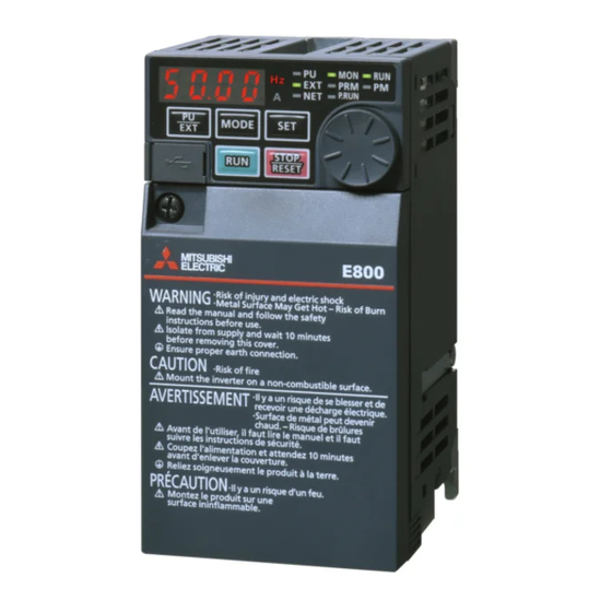
Inverter model Check the rating plate on the side of the product. Some characters in the model name indicate the specification as follows. FR-E8 0 - Rating plate Inverter model MODEL :FR-E820-0008-1 Input rating INPUT :XXXXX Output rating OUTPUT:XXXXX SERIAL SERIAL:XXXXXXXXXXX Country of origin MADE IN XXXXX... - Page 13 • E: The output specification for monitoring and the rated frequency are shown for the standard model, and the communication protocol group is shown for the Ethernet model and the safety communication model. Symbol Monitoring/protocol specification Rated frequency Control logic Pulse (terminal FM) 60 Hz Sink logic...
-
Page 14: Operation Steps
Operation steps : Initial setting Step of operation Frequency command Installation/mounting Inverter output Wiring of the power frequency supply and motor Time (Hz) Start command Control mode selection Start command via the PU/Ethernet connector of the inverter and plug-in to give a start to give a start to give a start option (Communication) - Page 15 Symbol Overview Refer to page Instruction Manual Install the inverter. (Connection) Instruction Manual Perform wiring for the power supply and the motor. (Connection) Select the control method (V/F control, Advanced magnetic flux vector control, Real sensorless vector control, Vector control, and PM sensorless vector control). Instruction Manual Give the start command via communication.
-
Page 16: Related Manuals
Related manuals The manuals related to the FR-E800 inverter are as follows. Name Manual number FR-E800 Inverter Safety Guideline IB-0600857ENG FR-E860 Inverter Safety Guideline IB-0600910ENG FR-E800-E Inverter Safety Guideline IB-0600860ENG FR-E860-E Inverter Safety Guideline IB-0600911ENG FR-E800-SCE Inverter Safety Guideline IB-0600921ENG FR-E860-SCE Inverter Safety Guideline IB-0600924ENG FR-E800 Instruction Manual (Connection) - Page 17 MEMO 1. Introduction 1.3 Related manuals...
- Page 18 CHAPTER 2 Basic Operation Operation panel ..............................19 Monitoring the inverter ............................27 Easy setting of the inverter operation mode ......................28 Frequently-used parameters (simple mode parameters)..................29 Basic operation procedure (PU operation) ......................34 Basic operation procedure (External operation) .....................39 Basic operation procedure (JOG operation) ......................46 I/O terminal function assignment ..........................48...
-
Page 19: Chapter 2 Basic Operation
Basic Operation This chapter explains the basic operation of this product. Always read the instructions before use. 2. Basic Operation... -
Page 20: Operation Panel
Operation panel 2.1.1 Components of the operation panel Standard model The operation panel cannot be removed from the inverter. 2. Basic Operation 2.1 Operation panel... - Page 21 ON when the PLC function of the inverter is valid. indicator The setting dial of the Mitsubishi Electric inverters. Turn the setting dial to change the setting of frequency or parameter, etc. Press the setting dial to perform the following operations: Setting dial •...
- Page 22 Ethernet model and safety communication model The operation panel cannot be removed from the inverter. 2. Basic Operation 2.1 Operation panel...
- Page 23 Appearance Name Description Shows a numeric value (readout) of a monitor item such as the frequency or a parameter Monitor (4-digit number. LED) (The monitor item can be changed according to the settings of Pr.52, Pr.774 to Pr.776.) Hz: ON when the actual frequency is monitored. (Blinks when the set frequency is monitored.) Unit indication A: ON when the current is monitored.
-
Page 24: Basic Operation Of The Operation Panel
2.1.2 Basic operation of the operation panel Basic operation (standard model) Operation mode switchover/Frequency setting External operation mode (displayed at power-ON) PU operation mode PU Jog operation mode Blinking Change the setting. Frequency setting written and complete Second screen Third screen First screen (Output frequency monitoring) - Page 25 Basic operation (Ethernet model and safety communication model) Operation mode switchover/Frequency setting Network operation mode (at power-ON) PU operation mode PU Jog operation mode Blinking Change the setting. Frequency setting written and complete Second screen Third screen First screen (Output frequency monitoring) (Output current monitoring)
-
Page 26: Digital Characters And Their Corresponding Printed Equivalents
V/F control as a batch. (Not displayed for the 575 V class.) Changes parameter settings as a batch. The target parameters include Automatic parameter communication parameters for the Mitsubishi Electric human machine setting interface (GOT) connection and the parameters for the rated frequency settings of 50/60 Hz. - Page 27 Parameter setting screen First screen (Output frequency monitoring) Parameter setting mode PU operation mode Blinking The present setting is Change the setting. Parameter write complete displayed. Hold down For a 4-digit parameter number The present setting is displayed. Change the setting. Hold down For a 5-digit parameter...
-
Page 28: Monitoring The Inverter
Monitoring the inverter 2.2.1 Monitoring of output current and output voltage • Press the SET key on the operation panel in the monitor mode to switch the monitor item between output frequency, output current, and output voltage. Operating procedure Press the MODE key during inverter operation to monitor the output frequency. The [Hz] LED turns ON. Press the SET key to monitor the output current. -
Page 29: Easy Setting Of The Inverter Operation Mode
Easy setting of the inverter operation mode The operation mode suitable for start and speed command combinations can be set easily using Pr.79 Operation mode selection. The following shows the procedure to operate with the external start command (STF/STR) and the frequency command by using the operation panel. -
Page 30: Frequently-Used Parameters (Simple Mode Parameters)
Frequently-used parameters (simple mode parameters) Parameters that are frequently used for the FR-E800 series are grouped as simple mode parameters. When Pr.160 User group read selection = "9999", only the simple mode parameters are displayed on the operation panel. This section explains the simple mode parameters. - Page 31 9109 PM motor. Changes parameter settings as a batch. The target parameters include communication Automatic 10, 12, 20, parameters for the Mitsubishi Electric human E431 9999 parameter setting 21, 9999 machine interface (GOT) connection and the parameters for the rated frequency settings of 50/60 Hz.
- Page 32 Simple mode parameters (Ethernet model and safety communication model) 2. Basic Operation 2.4 Frequently-used parameters (simple mode parameters)
- Page 33 9109 PM motor. Changes parameter settings as a batch. The target parameters include communication Automatic 10, 12, 20, parameters for the Mitsubishi Electric human E431 9999 parameter setting 21, 9999 machine interface (GOT) connection and the parameters for the rated frequency settings of 50/60 Hz.
- Page 34 Initial value for the FR-E860-0017(0.75K). Initial value for the FR-E820-0080(1.5K) to FR-E820-0175(3.7K), FR-E840-0040(1.5K) to FR-E840-0095(3.7K), and FR-E820S-0080(1.5K) or higher. Initial value for the FR-E820-0240(5.5K) or higher, FR-E840-0120(5.5K) or higher, FR-E860-0027(1.5K), and FR-E860-0040(2.2K). Initial value for the FR-E860-0061(3.7K) or higher. Initial value for the FR-E820-0175(3.7K) or lower, FR-E840-0095(3.7K) or lower, FR-E860-0061(3.7K) or lower, and FR-E820S-0110(2.2K) or lower.
-
Page 35: Basic Operation Procedure (Pu Operation)
Basic operation procedure (PU operation) Select a method to give the frequency command from the list below, and refer to the specified page for its procedure. Method to give the frequency command Refer to page Setting the frequency on the operation panel in the frequency setting mode Give commands by turning ON/OFF switches wired to inverter's terminals (multi-speed setting) Setting the frequency by inputting voltage signals Setting the frequency by inputting current signals... -
Page 36: Setting The Frequency With Switches (Multi-Speed Setting)
Parameters referred to Pr.7 Acceleration time, Pr.8 Deceleration timepage 196 Pr.79 Operation mode selectionpage 212 2.5.2 Setting the frequency with switches (multi-speed setting) • Use the RUN key on the operation panel to give a start command. • Turn ON the RH, RM, or RL signal to give a frequency command (multi-speed setting). •... -
Page 37: Setting The Frequency Using An Analog Signal (Voltage Input)
2.5.3 Setting the frequency using an analog signal (voltage input) • Use the RUN key on the operation panel to give a start command. • Use the frequency setting potentiometer to give a frequency command (by connecting it to terminals 2 and 5 (voltage input)). •... -
Page 38: Setting The Frequency Using An Analog Signal (Current Input)
2.5.4 Setting the frequency using an analog signal (current input) • Use the RUN key on the operation panel to give a start command. • Use the current regulator which outputs 4 to 20 mA to give a frequency command (by connecting it across terminals 4 and 5 (current input)). - Page 39 Parameters referred to Pr.7 Acceleration time, Pr.8 Deceleration timepage 196 Pr.79 Operation mode selectionpage 212 Pr.126 Terminal 4 frequency setting gain frequencypage 318 Pr.178 to Pr.184 (Input terminal function selection)page 328 C5(Pr.904) Terminal 4 frequency setting bias frequencypage 318 2. Basic Operation 2.5 Basic operation procedure (PU operation)
-
Page 40: Basic Operation Procedure (External Operation)
Basic operation procedure (External operation) Select a method to give the frequency command from the list below, and refer to the specified page for its procedure. Method to give the frequency command Refer to page Setting the frequency on the operation panel in the frequency setting mode Turning ON/OFF switches wired to inverter's terminals (multi-speed setting) Setting the frequency by inputting voltage signals Setting the frequency by inputting current signals... -
Page 41: Setting The Frequency And Giving A Start Command With Switches (Multi-Speed Setting) (Pr.4 To Pr.6)
NOTE • When both the forward rotation start switch (STF signal) and the reverse rotation start switch (STR signal) are turned ON, the motor cannot be started. If both are turned ON while the inverter is running, the inverter decelerates to a stop. •... -
Page 42: Setting The Frequency Using An Analog Signal (Voltage Input)
NOTE • When both the forward rotation start switch (STF signal) and the reverse rotation start switch (STR signal) are turned ON, the motor cannot be started. If both are turned ON while the inverter is running, the inverter decelerates to a stop. •... -
Page 43: Changing The Frequency (Initial Value: 60 Hz) At The Maximum Voltage Input (Initial Value: 5 V)
NOTE • When both the forward rotation start switch (STF signal) and the reverse rotation start switch (STR signal) are turned ON, the motor cannot be started. If both are turned ON while the inverter is running, the inverter decelerates to a stop. •... -
Page 44: Setting The Frequency Using An Analog Signal (Current Input)
• Other adjustment methods for the frequency setting voltage gain are the following: adjustment by applying a voltage directly across terminals 2 and 5, and adjustment using a specified point without applying a voltage across terminals 2 and 5. (Refer page 318.) Parameters referred to... -
Page 45: Changing The Frequency (Initial Value: 60 Hz) At The Maximum Current Input (Initial Value: 20 Ma)
NOTE • When both the forward rotation start switch (STF signal) and the reverse rotation start switch (STR signal) are turned ON, the motor cannot be started. If both are turned ON while the inverter is running, the inverter decelerates to a stop. •... - Page 46 Parameters referred to Pr.126 Terminal 4 frequency setting gain frequencypage 318 C5(Pr.904) Terminal 4 frequency setting bias frequencypage 318 C7(Pr.905) Terminal 4 frequency setting gainpage 318 2. Basic Operation 2.6 Basic operation procedure (External operation)
-
Page 47: Basic Operation Procedure (Jog Operation)
Basic operation procedure (JOG operation) 2.7.1 Giving a start command by using external signals for JOG operation • The JOG signal can be input only via a control terminal. • JOG operation is performed while the JOG signal is ON. •... -
Page 48: Giving A Start Command From The Operation Panel For Jog Operation
Pr.178 to Pr.184 (Input terminal function selection)page 328 2.7.2 Giving a start command from the operation panel for JOG operation • JOG operation is performed while the RUN key on the operation panel is pressed. Operation panel The following shows the procedure to operate at 5 Hz. Operating procedure Turning ON the power of the inverter The operation panel is in the monitor mode. -
Page 49: I/O Terminal Function Assignment
I/O terminal function assignment • Functions can be assigned to the external I/O terminals (physical terminals) or communication (virtual terminals) by setting parameters. FR-E800 FR-E800-E Output Input Output terminal Input terminal (physical terminal) (physical terminal) Input terminal Input (physical terminal) Plug-in option Output Plug-in option... - Page 50 • Use the following parameters to assign functions to input terminals. Check the terminal available for each parameter. External input terminal (physical terminal) Terminal Input via name communication FR-E800 FR-E800-E FR-E800-SCE STF/DI0 ○ (STF) ○ (DI0) — ○ STR/DI1 ○ (STR) ○...
- Page 51 MEMO 2. Basic Operation 2.8 I/O terminal function assignment...
-
Page 52: Chapter 3 Parameters
CHAPTER 3 Parameters Parameter initial value groups ..........................52 Parameter list (by parameter number)........................53 Use of a function group number for the identification of parameters ..............78 Parameter list (by function group number) ......................80... -
Page 53: Parameter Initial Value Groups
Parameters This chapter explains the function setting for use of this product. Always read the instructions before use. The following marks are used to indicate the controls. (Parameters without any mark are valid for all the controls.) Mark Control method Applied motor V/F control Advanced magnetic flux vector control... - Page 54 Parameter list (by parameter number) For simple variable-speed operation of the inverter, the initial values of the parameters may be used as they are. Set the necessary parameters to meet the load and operational specifications. Parameter's setting, change and check can be made on the operation panel.
- Page 55 Initial Minimum Refer Customer value Function Name Setting range setting group to page setting increments Gr.1 Gr.2 DC injection brake operation G100 0 to 120 Hz 0.01 Hz 3 Hz frequency DC injection brake operation G101 0 to 10 s, 8888 0.1 s 0.5 s time...
- Page 56 Initial Minimum Refer Customer value Function Name Setting range setting group to page setting increments Gr.1 Gr.2 M441 Up-to-frequency sensitivity 0% to 100% 0.1% M442 Output frequency detection 0 to 590 Hz 0.01 Hz 6 Hz Output frequency detection M443 0 to 590 Hz, 9999 0.01 Hz 9999...
- Page 57 Initial Minimum Refer Customer value Function Name Setting range setting group to page setting increments Gr.1 Gr.2 — H300 Retry selection 0 to 5 Stall prevention operation — H611 0 to 590 Hz 0.01 Hz 60 Hz 50 Hz reduction starting frequency Number of retries at fault H301 0 to 10, 101 to 110...
- Page 58 Initial Minimum Refer Customer value Function Name Setting range setting group to page setting increments Gr.1 Gr.2 C101 Motor capacity 0.1 to 30 kW, 9999 0.01 kW 9999 345, C102 Number of motor poles 2, 4, 6, 8, 10, 12, 9999 1 9999 345, C125...
- Page 59 Initial Minimum Refer Customer value Function Name Setting range setting group to page setting increments Gr.1 Gr.2 PID control automatic A612 0 to 590 Hz, 9999 0.01 Hz 9999 switchover frequency 0, 20, 21, 40 to 43, 50, 51, 60, 61, 1000, 1001, 380, A610 PID action selection...
- Page 60 Initial Minimum Refer Customer value Function Name Setting range setting group to page setting increments Gr.1 Gr.2 M020 Watt-hour meter clear 0, 10, 9999 9999 M030 Operation hour meter clear 0, 9999 9999 User group registered E441 9999, (0 to 16) display/batch clear E442 User group registration...
- Page 61 Initial Minimum Refer Customer value Function Name Setting range setting group to page setting increments Gr.1 Gr.2 0, 1, 3, 4, 7, 8, 11 to 16, 20, 25, 26, 30 to 35, 39 RUN terminal function M400 to 41, 44 to 48, 57, 64, selection 70, 80, 81, 90 to 93, 95, 96, 98 to 101, 103,...
- Page 62 Pr.200 to Pr.299 Initial Minimum Refer Customer value Function Name Setting range setting group to page setting increments Gr.1 Gr.2 232 to D308 to Multi-speed setting (speed 8 0 to 590 Hz, 9999 0.01 Hz 9999 D315 to speed 15) Soft-PWM operation —...
- Page 63 Initial Minimum Refer Customer value Function Name Setting range setting group to page setting increments Gr.1 Gr.2 A100 Brake opening frequency 0 to 30 Hz 0.01 Hz 3 Hz A101 Brake opening current 0% to 400% 0.1% 130% Brake opening current A102 0 to 2 s 0.1 s...
- Page 64 Pr.300 to Pr.399 Initial Minimum Refer Customer value Function Name Setting range setting group to page setting increments Gr.1 Gr.2 M410 DO0 output selection 9999 0, 1, 3, 4, 7, 8, 11 to 16, 20, 25, 26, 30 to 35, 39 M411 DO1 output selection 9999...
- Page 65 Initial Minimum Refer Customer value Function Name Setting range setting group to page setting increments Gr.1 Gr.2 — B003 Position control gain 0 to 150 s 10 s Default gateway address 1 N620 [E800-(SC)E] Default gateway address 2 N621 [E800-(SC)E] 0 to 255 Default gateway address 3 N622...
- Page 66 Initial Minimum Refer Customer value Function Name Setting range setting group to page setting increments Gr.1 Gr.2 E710 Maintenance timer 0 (1 to 9998) Maintenance timer warning E711 0 to 9998, 9999 9999 output set time — M001 Speed setting reference 1 to 590 Hz 0.01 Hz 60 Hz 50 Hz...
- Page 67 Initial Minimum Refer Customer value Function Name Setting range setting group to page setting increments Gr.1 Gr.2 Multiple rating setting [3- E301 1, 2 phase] — F103 Holding time at a start 0 to 10 s, 9999 0.1 s 9999 Second motor online auto —...
- Page 68 Initial Minimum Refer Customer value Function Name Setting range setting group to page setting increments Gr.1 Gr.2 G410 Speed smoothing control 0% to 200% 0.1% Speed smoothing cutoff G411 0 to 120 Hz 0.01 Hz 20 Hz frequency Regeneration avoidance —...
- Page 69 Initial Minimum Refer Customer value Function Name Setting range setting group to page setting increments Gr.1 Gr.2 Starting resistance tuning C288 0% to 200%, 9999 0.1% 9999 compensation coefficient 2 Second motor induced 0 to 5000 mV (rad/s), 0.1 mV C230 9999 voltage constant (phi f)
- Page 70 Initial Minimum Refer Customer value Function Name Setting range setting group to page setting increments Gr.1 Gr.2 H410 Speed limit selection 0, 1 H411 Speed limit 0 to 400 Hz 0.01 Hz 60 Hz 50 Hz H412 Reverse-side speed limit 0 to 400 Hz, 9999 0.01 Hz 9999...
- Page 71 Initial Minimum Refer Customer value Function Name Setting range setting group to page setting increments Gr.1 Gr.2 Analog input offset T007 0% to 200% 0.1% 100% adjustment G103 Brake operation selection 0 to 2 H417 Speed deviation time 0 to 100 s 0.1 s G217 Excitation ratio...
- Page 72 Initial Minimum Refer Customer value Function Name Setting range setting group to page setting increments Gr.1 Gr.2 Cumulative power monitor 270, M023 0 to 4, 9999 9999 digit shifted times M200 Load factor 30% to 150% 0.1% 100% Energy saving monitor Inverter rated M201 0.1 to 30 kW...
- Page 73 Initial Minimum Refer Customer value Function Name Setting range setting group to page setting increments Gr.1 Gr.2 1020 A900 Trace operation selection 0 to 3 1, 2, 5, 10, 50, 100, 1022 A902 Sampling cycle 500, 1000 1023 A903 Number of analog channels 1 to 8 1024 A904...
- Page 74 Initial Minimum Refer Customer value Function Name Setting range setting group to page setting increments Gr.1 Gr.2 AM output offset calibration — 1200 M390 2700 to 3300 3000 [E800-4][E800-5] Inverter identification enable/ — 1399 N649 disable selection [E800- 0, 1 (SC)E] ...
- Page 75 Initial Minimum Refer Customer value Function Name Setting range setting group to page setting increments Gr.1 Gr.2 IP address 1 (Ethernet) [E800- 1434 N600 0 to 255 (SC)E] IP address 2 (Ethernet) [E800- 1435 N601 0 to 255 (SC)E] IP address 3 (Ethernet) [E800- 1436 N602 0 to 255...
- Page 76 Initial Minimum Refer Customer value Function Name Setting range setting group to page setting increments Gr.1 Gr.2 Load characteristics 1480 H520 0, 1 (2 to 5, 81 to 85) measurement mode Load characteristics load 0% to 400%, 8888, 1481 H521 0.1% 9999 reference 1...
- Page 77 Alphabet (calibration parameters, etc.) Initial Minimum Refer Customer value Function Name Setting range setting group to page setting increments Gr.1 Gr.2 FM terminal calibration M310 — — — [E800-1] (900) AM terminal calibration M320 — — — [E800-4][E800-5] (901) Terminal 2 frequency setting T200 0 to 590 Hz...
- Page 78 Differs depending on the capacity. 6%: FR-E820-0015(0.2K) or lower and FR-E820S-0015(0.2K) or lower 4%: FR-E820-0030(0.4K) or higher, FR-E840-0016(0.4K) or higher, and FR-E820S-0030(0.4K) or higher 1%: FR-E860-0017(0.75K) or higher The setting is available when a plug-in option for Vector control is installed. On the LCD operation panel used as the command source, the parameter number in parentheses appears instead of that starting with the letter C.
- Page 79 Use of a function group number for the identification of parameters A parameter identification number shown on the PU can be switched from a parameter number to a function group number. As parameters are grouped by function and displayed by the group, the related parameters can be set continually at a time. ...
- Page 80 Changing the setting value Turn the setting dial or press the UP/DOWN key to change the value to "60.00". Press the SET key to confirm the setting. "60.00" blinks after the setting is completed. 3. Parameters 3.3 Use of a function group number for the identification of parameters...
- Page 81 Parameter list (by function group number) E: Environment setting Refer Pr. group Name to page parameters Inrush current limit circuit life E701 display Parameters for the inverter operating environment. Control circuit capacitor life E702 Refer display Pr. group Name to page Main circuit capacitor life E703...
- Page 82 Refer Refer Pr. group Name Pr. group Name to page to page Automatic acceleration/ 209, First free thermal reduction F500 H001 deceleration frequency 1 F510 Reference current First free thermal reduction H002 ratio 1 Reference value at F511 acceleration First free thermal reduction H003 frequency 2 Reference value at...
- Page 83 Refer Refer Pr. group Name Pr. group Name to page to page Stall prevention operation Operating time carrying-over M031 H610 level compensation factor at times double speed Frequency monitoring M040 Stall prevention operation reference H611 reduction starting frequency M041 Current monitoring reference Stall prevention operation M042 Torque monitoring reference...
- Page 84 Refer Refer Pr. group Name Pr. group Name to page to page M415 DO5 output selection Terminal 2 frequency setting T203 gain (903) M416 DO6 output selection Terminal 4 frequency setting M420 RA1 output selection T400 bias frequency (904) M421 RA2 output selection Terminal 4 frequency setting T401...
- Page 85 Refer Refer Pr. group Name Pr. group Name to page to page C108 Motor inertia (exponent) 345, C220 Second motor constant (R1) 355, 345, C110 Auto tuning setting/status 355, C221 Second motor constant (R2) C111 Online auto tuning selection Second motor constant (L1) / 345, C222 d-axis inductance (Ld)
- Page 86 Refer Refer Pr. group Name Pr. group Name to page to page Amplitude compensation PLC function flash memory A303 A804 amount during acceleration clear A304 Amplitude acceleration time User parameter auto storage A805 function selection A305 Amplitude deceleration time A810 to 1150 to PLC function user parameters A600...
- Page 87 Refer Refer Pr. group Name Pr. group Name to page to page Operation frequency during Link speed and duplex mode N014 N641 1426 communication error selection [E800-(SC)E] PU communication station N642 1455 Keepalive time [E800-(SC)E] N020 number Ethernet signal loss detection N021 PU communication speed N643...
- Page 88 (G) Control parameters Refer Pr. group Name to page Parameters for motor control. G224 Model speed control gain Refer G230 Torque bias selection Pr. group Name to page G231 Torque bias 1 G000 Torque boost Simple Simple Simple G232 Torque bias 2 G233 Torque bias 3...
- Page 89 MEMO 3. Parameters 3.4 Parameter list (by function group number)
- Page 90 CHAPTER 4 Control Method Vector control and Real sensorless vector control ....................94 Changing the control method and mode.........................97 Selecting the Advanced magnetic flux vector control ...................102 Selecting the PM sensorless vector control......................104...
- Page 91 Motor Condition Mitsubishi Electric standard efficiency motor (SF-JR) Mitsubishi Electric high-efficiency motor (SF-HR) Mitsubishi Electric constant-torque motor (SF-JRCA 4P, SF-HRCA) Offline auto tuning is not required. Mitsubishi Electric high-performance energy-saving motor (SF-PR) Mitsubishi Electric geared motor (constant-torque) (GM-[]) Other motors (other manufactures' motors) Offline auto tuning is required.
- Page 92 Set the rated motor current to about 40% or higher of the inverter rated current. • Offline auto tuning is performed. Offline auto tuning is required under Real sensorless vector control even when the Mitsubishi Electric motor is used since the wiring length affects the operation.
- Page 93 Mitsubishi Electric inverter-driven geared motor for encoder feedback control (GM-DP) The offline auto tuning is not required. Mitsubishi Electric standard efficiency motor with encoder (SF- Mitsubishi Electric high-efficiency motor with encoder (SF-HR) Mitsubishi Electric constant-torque motor with encoder (SF- JRCA 4P, SF-HRCA)
- Page 94 NOTE • The PM sensorless vector control requires the following conditions. • For the motor capacity, the rated motor current should be equal to or less than the rated inverter current. (Note that the motor rated current should be 0.4 kW or higher (0.1 kW or higher for the 200 V class).) If a motor with substantially low rated current compared with the inverter rated current is used, speed and torque accuracies may deteriorate due to torque ripples, etc.
-
Page 95: Vector Control And Real Sensorless Vector Control
Vector control and Real sensorless vector control Vector control is one of the control techniques for driving an induction motor. To help explain Vector control, the fundamental equivalent circuit of an induction motor is shown below. r1: Primary resistance r2: Secondary resistance 1: Primary leakage inductance 2: Secondary leakage inductance M: Mutual inductance... - Page 96 • It is applicable to fast response applications with which induction motors were previously regarded as difficult to use. Applications requiring a wide variable-speed range from extremely low speed to high speed, frequent acceleration/ deceleration operations, continuous four-quadrant operations, etc. •...
- Page 97 Block diagram of Vector control Encoder modulation Pre-excitation φ 2 Magnetic current flux Output control control voltage conversion Torque ω ω 0 Speed current control control ω FB ω 0 ω FB ω s Current conversion Slip calculation φ 2 Magnetic flux calculation...
-
Page 98: Changing The Control Method And Mode
Changing the control method and mode Set the control method and the control mode. V/F control, Advanced magnetic flux vector control, Real sensorless vector control, Vector control, and PM sensorless vector control are available. The available control modes are speed control and torque control modes. •... - Page 99 • To enable the control method and the control mode selected in Pr.800 (Pr.451), the condition to start operation must be satisfied as shown in the following table. Otherwise the operation does not start due to the setting error (SE) alarm when the start signal is input.
- Page 100 Vector control test operation, PM sensorless vector control test operation (Pr.800 = "9 or 19") • A test operation for speed control is available without connecting a motor to the inverter. The speed calculation changes to track the speed command, and such speed changes can be checked on the operation panel or by outputting it as analog signals to terminal FM or AM.
- Page 101 —: Not available Monitoring on the Output via Monitoring on the Output via Monitor item Monitor item operation panel FM/AM operation panel FM/AM Output frequency ○ ○ Feedback pulse × — Output current × × Trace status ○ — Output voltage ×...
- Page 102 • To input the RT signal, set "3" in any parameter from Pr.178 to Pr.189 (Input terminal function selection) to assign the function. To input the X18 signal, set "18" in any parameter from Pr.178 to Pr.189 (Input terminal function selection) to assign the function.
-
Page 103: Selecting The Advanced Magnetic Flux Vector Control
• 200/400 V class Motor Pr.71 setting Remarks SF-JR 0 (initial value) (3) SF-JR 4P 1.5 kW or lower Mitsubishi Electric standard efficiency motor SF-HR Mitsubishi Electric high-efficiency motor Others 0 (3) Offline auto tuning is required. SF-JRCA 4P SF-HRCA Mitsubishi Electric constant-torque motor Other (SF-JRC, etc.) - Page 104 • Perform the offline auto tuning (Pr.96). (Refer to page 345.) • Select the online auto tuning (Pr.95). (Refer to page 362.) NOTE • To perform driving in a better accuracy, perform offline auto tuning, then set the online auto tuning, and select Real sensorless vector control.
-
Page 105: Selecting The Pm Sensorless Vector Control
Selecting the PM sensorless vector control Initializing the parameters required for the PM sensorless vector control (Pr.998) • Use PM parameter initialization to set the parameters required for driving a PM motor. • Perform offline auto tuning before setting Pr.998. (Refer to page 345.) •... - Page 106 • Performing Parameter clear or All parameter clear resets these parameter settings to the settings required to drive an induction motor. Setting PM motor Setting increments PM motor Induction motor (rotations per (frequency) Name minute) 0 (initial value) 8009, 0, 8109, 8009, 9009 8109, 9109 9009...
- Page 107 Setting for the V/F control by selecting PM parameter initialization on the operation panel ("PM") • When the control method is changed from PM sensorless vector control to V/F control, all the parameter settings required to drive an induction motor are automatically set. (Refer to page 104.) The following shows the procedure to change the control method from PM sensorless vector control to V/F control by selecting...
- Page 108 CHAPTER 5 Speed Control Setting procedure of Real sensorless vector control (speed control) ..............111 Setting procedure of Vector control (speed control) .....................112 Setting procedure of PM sensorless vector control (speed control) ..............113 Setting the torque limit level..........................114 Performing high-accuracy, fast-response control (gain adjustment for Real sensorless vector control, Vector control, and PM sensorless vector control)121 Speed feed forward control, model adaptive speed control..................124 Torque bias................................126...
- Page 109 Speed Control Refer Purpose Parameter to set to page P.H500, P.H700 to P.H704, Pr.22, Pr.801, To limit the torque during speed P.H710, P.H720, Pr.803, Pr.810 Torque limit control P.H721, P.H730, to Pr.817, P.D030, P.T040, Pr.858, Pr.874 P.G210 P.G211, P.G212, Pr.820, Pr.821, To adjust the speed control gain Speed control P gain, speed control integral time P.G311, P.G312...
- Page 110 Control block diagram Analog input offset adjustment [Pr. 849] Operation Mode Terminal 2 bias [C2, C3(Pr.902)] AU-OFF [Pr. 79] Terminal 2 gain [Pr. 125, C4(Pr.903)] Terminal 2 Analog Terminal 4 bias [C5, C6(Pr.904)] input Terminal 4 gain [Pr. 126, C7(Pr.905)] AU-ON Terminal 4 selection...
- Page 111 Speed feed forward control Speed feed forward Speed feed torque limit forward [Pr. 879] filter [Pr. 878] Load inertia ratio Speed feed forward gain [Pr. 880] [Pr. 881] Model adaptive speed control J [Pr. 880] Torque coefficient Model speed calculation [Pr.
-
Page 112: Setting Procedure Of Real Sensorless Vector Control (Speed Control)
Setting procedure of Real sensorless vector control (speed control) Sensorless Sensorless Sensorless Operating procedure Perform wiring properly. (Refer to the Instruction Manual (Connection).) Set the applied motor (Pr.71). (Refer to page 340.) Set Pr.71 Applied motor to "0" (standard motor) or "10" (constant-torque motor). Set the overheat protection of the motor (Pr.9). -
Page 113: Setting Procedure Of Vector Control (Speed Control)
Setting procedure of Vector control (speed control) Vector Vector Vector Operating procedure Perform wiring properly. (Refer to the Instruction Manual (Connection).) Install a Vector control compatible option. Set the applied motor and encoder (Pr.71, Pr.359, Pr.369). (Refer to page 340, page 365.) Set the overheat protection of the motor (Pr.9). -
Page 114: Setting Procedure Of Pm Sensorless Vector Control (Speed Control)
Setting procedure of PM sensorless vector control (speed control) This inverter is set for an induction motor in the initial setting. Follow the following procedure to change the setting for the PM sensorless vector control. Operating procedure Set the applied motor (Pr.9, Pr.71, Pr.80, Pr.81, Pr.83, and Pr.84). (Refer to page 340, page... -
Page 115: Setting The Torque Limit Level
Setting the torque limit level Sensorless Sensorless Sensorless Vector Vector Vector Limit the output torque not to exceed the specified value. The torque limit level can be set in a range of 0% to 400%. The TL signal can be used to switch between two types of torque limit. - Page 116 Setting Name Initial value Description range 0% to 400% Set the torque limit value during acceleration. Torque limit level during 9999 H720 acceleration 9999 The same torque limit as constant speed. 0% to 400% Set the torque limit value during deceleration. Torque limit level during 9999 H721...
- Page 117 • To set individually for each quadrant, use Pr.812 Torque limit level (regeneration), Pr.813 Torque limit level (3rd quadrant), Pr.814 Torque limit level (4th quadrant). When "9999" is set, Pr.22 setting is regarded as torque limit level in all the quadrants. Torque limit Reverse Forward...
- Page 118 Torque limit Forward driving Reverse regeneration Pr.805(Pr.806) Pr.805(Pr.806) quad4 quad1 RWwC RWwC Speed quad3 quad2 Pr.805(Pr.806) Pr.805(Pr.806) RWwC RWwC Reverse driving Forward regeneration Reverse rotation Forward rotation − Rated speed NOTE • For the details of the CC-Link communication, refer to the FR-A8NC E kit Instruction Manual. For the details of the CC-Link IE TSN or CC-Link IE Field Network, refer to the Instruction Manual (Communication).
- Page 119 • When the difference between the set speed and rotation speed is -2 Hz or less, the torque limit level during deceleration Torque limit level during deceleration (Pr.817) activates. Output frequency -2 Hz < set speed - rotation speed < 2 Hz (Hz) frequency -2 Hz...
- Page 120 • To avoid overload or overcurrent of the inverter or motor, use Pr.801 Output limit level to limit the torque current. Pr.801 setting Description 0% to 400% Set the torque current limit level. 9999 The torque limit setting value (Pr.22, Pr.812 to Pr.817, etc.) is used for limiting the torque current. Pr.803=0 Pr.803=1 Torque...
- Page 121 • When a high load is applied and the torque limit is activated under speed control, the motor stalls. At this time, if the rotation speed is lower than the value set in Pr.865 Low speed detection and the output torque exceeds the level set in Pr.874 OLT level setting, and this state continues for 3 seconds, Stall prevention stop (E.OLT) is activated and the inverter output is shut off.
-
Page 122: Performing High-Accuracy, Fast-Response Control
Performing high-accuracy, fast-response control (gain adjustment for Real sensorless vector control, Vector control, and PM sensorless vector control) Sensorless Sensorless Sensorless Vector Vector Vector Gain adjustment is useful for achieving optimum machine performance or improving unfavorable conditions, such as vibration and acoustic noise during operation with high load inertia or gear backlash. - Page 123 JM: Motor inertia Actual speed gain = Speed gain of a single motor JM+JL JL: Load inertia converted as the motor axis inertia Adjustment procedure Change the Pr.820 setting while checking the conditions. If it cannot be adjusted well, change Pr.821 setting, and perform step again.
- Page 124 • Adjustment method: Movement / condition Adjustment method Pr.820 Speed control P gain 1 must be set higher according to the motor inertia. Motor rotation speed in the low- For multi-pole motors, because the inertia of the motor itself tends to be large, first speed range is unstable.
-
Page 125: Speed Feed Forward Control, Model Adaptive Speed Control
Speed feed forward control, model adaptive speed control Sensorless Sensorless Sensorless Vector Vector Vector • Speed feed forward control or model adaptive speed control can be selected using parameter settings. Under speed feed forward control, the motor trackability for speed command changes can be improved. Under model adaptive speed control, the speed trackability and the response level to motor external disturbance torque can be adjusted individually. - Page 126 • The inertia ratio of Pr.880 is used when the speed controller on the model side calculates the torque current command value. • The torque current command of the speed controller on the model side is added to the output of the actual speed controller, and set as the input of the iq current control.
-
Page 127: Torque Bias
Torque bias Sensorless Sensorless Sensorless Vector Vector Vector The torque bias function can be used to make the starting torque start-up faster. At this time, the motor starting torque can be adjusted with a contact signal or analog signal. Setting Name Initial value Description... - Page 128 • To input the X42 signal, set "42" in any of Pr.178 to Pr.189 (Input terminal function selection) to assign the function to a terminal, and to input the X43 signal, set "43". Torque bias selection 1 Torque bias selection 2 Torque bias amount (X42) (X43)
- Page 129 Setting the torque bias amount automatically using terminal 4 (Pr.840 = "3", Pr.846) • The settings of C38 Terminal 4 bias command (torque/magnetic flux), C39 Terminal 4 bias (torque/magnetic flux), C40 Terminal 4 gain command (torque/magnetic flux), C41 Terminal 4 gain (torque/magnetic flux) and Pr.846 Torque bias balance compensation can be set automatically according to the load.
- Page 130 NOTE • When torque bias is enabled and Pr.858 = "6", terminal 4 operates as a torque command. • Changing the terminal assignment using Pr.178 to Pr.189 (Input terminal function selection) may affect the other functions. Set parameters after confirming the function of each terminal. •...
-
Page 131: Avoiding Motor Overrunning
Avoiding motor overrunning Vector Vector Vector Motor overrunning due to excessive load torque or an error in the setting of the number of encoder pulses can be avoided. Setting Name Initial value Description range Set the speed deviation excess detection frequency (difference between the rotation speed (estimated value) Speed deviation excess detection 0 to 30 Hz... - Page 132 NOTE • When the automatic restart after instantaneous power failure function is selected (Pr.57 Restart coasting time ≠ "9999") and the setting value for the number of encoder pulses is lower than the actual number of pulses, the output speed is limited with the synchronous speed of the value of Pr.1 Maximum frequency + Pr.873.
-
Page 133: Troubleshooting In The Speed Control
Troubleshooting in the speed control Sensorless Sensorless Sensorless Vector Vector Vector Condition Possible cause Countermeasure • Check the wiring. Select V/F control (set "9999" in Pr.80 Motor capacity or Pr.81 Number of motor poles, and "40" in Pr.800 Control method selection) and check the motor rotation direction. - Page 134 Condition Possible cause Countermeasure • Check that the speed command sent from the controller is correct. (Take EMC measures.) Speed command varies. • Set Pr.72 lower. • Set Pr.822 Speed setting filter 1 higher. (Refer to page 316.) Motor speed •...
- Page 135 MEMO 5. Speed Control 5.9 Troubleshooting in the speed control...
- Page 136 CHAPTER 6 Torque Control Torque control...............................136 Setting procedure of Real sensorless vector control (torque control)..............141 Setting procedure for Vector control (torque control)....................142 Torque command..............................143 Speed limit ................................147 Torque control gain adjustment ..........................149 Troubleshooting in torque control .........................151...
-
Page 137: Torque Control
Torque Control Refer Purpose Parameter to set to page Torque command source selection or P.D400 to P.D402, P.G210, Torque command Pr.801, Pr.803 to Pr.806 torque command value setting P.H704 To prevent the motor from Speed limit P.H410 to P.H412 Pr.807 to Pr.809 overspeeding Torque control gain P.G213, P.G214, P.G313,... - Page 138 Block diagram Constant power range Torque command torque characteristic selection Terminal 4 bias [C38,C39(Pr.932)] source selection [Pr.803] [Pr.804] Terminal 4 gain [C40,C41(Pr.933)] Terminal 4 [Pr. 858 = 4] RT-OFF [Pr.826≠9999] Torque [Pr.826] setting filter [Pr.74] [Pr.826 = 9999] RT-ON [Pr.836≠9999] [Pr.836] [Pr.74]...
- Page 139 Analog input offset Speed limit adjustment Terminal 2 bias [C2,C3(Pr.902)] [Pr.849] AU-OFF Terminal 2 gain [Pr.125, C4(Pr.903)] Terminal 2 Terminal 4 bias [C5,C6(Pr.904)] Analog input AU-ON Terminal 4 gain [Pr.126, C7(Pr.905)] Terminal 4 selection [Pr. 858 = 0] [Pr. 73] RT-OFF [Pr.822 ≠...
- Page 140 Operation transition Speed limit value is increased up to preset value according to the Pr.7 Speed limit value Acceleration time setting. Speed limit value is decreased down to zero according to the Pr.8 Deceleration time setting. Torque control Speed Speed limit Speed limit Start signal...
- Page 141 • Speed control is performed when the actual speed exceeds the speed limit value. • At the STF signal OFF, the speed limit value is lowered in accordance with the setting of Pr.8. • Under torque control, the actual operation speed is a constant speed when the torque command and load torque are balanced.
-
Page 142: Setting Procedure Of Real Sensorless Vector Control (Torque Control)
Setting procedure of Real sensorless vector control (torque control) Sensorless Sensorless Sensorless Operating procedure Perform wiring properly. (Refer to the Instruction Manual (Connection).) Make the motor setting (Pr.71). (Refer to page 340.) Set Pr.71 Applied motor to "0" (standard motor) or "10" (constant-torque motor). Set the motor overheat protection (Pr.9). -
Page 143: Setting Procedure For Vector Control (Torque Control)
Setting procedure for Vector control (torque control) Vector Vector Vector Operating procedure Perform secure wiring. (Refer to the Instruction Manual (Connection).) Install a Vector control compatible option. Set the motor and the encoder (Pr.71, Pr.359, Pr.369). (Refer to page 340, page 365.) Set the overheat protection of the motor (Pr.9). -
Page 144: Torque Command
Torque command Sensorless Sensorless Sensorless Vector Vector Vector For torque control selection, the torque command source can be selected. Initial Name Setting range Description value 0% to 400% Set the torque current limit level. Output limit level 9999 H704 9999 The torque limit setting value is used for limiting the torque current level. - Page 145 • Torque commands given by analog inputs can be calibrated by the calibration parameters C38 (Pr.932) to C41 (Pr.933) (Refer to page 323.) Torque command 150% 100% Terminal 4 analog input Torque command given by parameter (Pr.804 = "1") •...
- Page 146 NOTE • For the details of the CC-Link communication, refer to the FR-A8NC E kit Instruction Manual. For the details of the CC-Link IE TSN or CC-Link IE Field Network, refer to the Instruction Manual (Communication). For the details of the PROFIBUS-DP communication, refer to the FR-A8NP E kit Instruction Manual.
- Page 147 Parameters referred to Pr.858 Terminal 4 function assignmentpage 315 Calibration parameter C38 (Pr.932) to C41 (Pr.933) (terminal 4 bias, gain torque)page 323 6. Torque Control 6.4 Torque command...
-
Page 148: Speed Limit
Speed limit Sensorless Sensorless Sensorless Vector Vector Vector When operating under torque control, motor overspeeding may occur if the load torque drops to a value less than the torque command value, etc. Set the speed limit value to prevent overspeeding. If the actual speed reaches or exceeds the speed limit value, the control method switches from torque control to speed control, preventing overspeeding. - Page 149 NOTE • The second acceleration/deceleration time can be set. • When speed limit command exceeds Pr.1 Maximum frequency setting, the speed limit value becomes Pr.1 setting. When speed limit command falls below Pr.2 Minimum frequency setting, the speed limit value becomes Pr.2 setting. Also, the speed limit command is smaller than Pr.
-
Page 150: Torque Control Gain Adjustment
Torque control gain adjustment Sensorless Sensorless Sensorless Vector Vector Vector Operation is normally stable enough in the initial setting, but some adjustments can be made if abnormal vibration, noise or overcurrent occur for the motor or machinery. Setting Name Initial value Description range Torque control P gain 1 (current loop... - Page 151 If it cannot be adjusted well, change the Pr.825 setting, and perform step 1 again. Adjustment method Set Pr.824 lower and Pr.825 longer. First, lower Pr.824 and then check of there is still any abnormal vibration, noise or current from the motor. If it still requires improvement, make Pr.825 longer. Lower the setting by 10% each time and set a value that is approximately 80% to 90% of the setting Pr.824 immediately before the abnormal noise or current improves.
-
Page 152: Troubleshooting In Torque Control
Troubleshooting in torque control Sensorless Sensorless Sensorless Vector Vector Vector Condition Possible cause Countermeasure • There is incorrect phase sequence • Check the wiring. (Refer to the Instruction Manual between the motor wiring and (Connection).) encoder wiring. • Pr.800 Control method selection •... - Page 153 MEMO 6. Torque Control 6.7 Troubleshooting in torque control...
- Page 154 CHAPTER 7 Adjustment during Real sensorless vector control, Vector control, PM sensorless vector control Speed detection filter ............................154 Excitation ratio ..............................155 Gain adjustment of current controllers for the d axis and the q axis..............156...
- Page 155 Adjustment during Real sensorless vector control, Vector control, PM sensorless vector control Refer to Purpose Parameter to set page To stabilize speed feedback signal Speed detection filter P.G215, P.G315 Pr.823, Pr.833 To change excitation ratio Excitation ratio P.G217 Pr.854 Speed detection filter Vector Vector Vector...
- Page 156 Excitation ratio Sensorless Sensorless Sensorless Vector Vector Vector The excitation ratio can be lowered to enhance efficiency for light loads. (Motor magnetic noise can be reduced.) Setting Name Initial value Description range Excitation ratio 100% 0% to 100% Set an excitation ratio when there is no load. G217 Excitation ratio (Initial value)
- Page 157 Gain adjustment of current controllers for the d axis and the q axis Vector Vector Vector The gain of the current controller can be adjusted. Initial Setting Name Description value range Torque control P gain 1 (current 100% 0% to 500% The proportional gain of the current controller is set.
- Page 158 CHAPTER 8 (E) Environment Setting Parameters Clock..................................158 Reset selection / disconnected PU detection / PU stop selection ................161 PU display language selection..........................164 Buzzer control...............................165 PU contrast adjustment ............................166 Automatic frequency setting / key lock operation selection ..................167 Frequency change increment amount setting (standard model) ................169 RUN key rotation direction selection........................170 Multiple rating setting............................171 8.10...
-
Page 159: Clock
(E) Environment Setting Parameters Refer to Purpose Parameter to set page To set the time Clock P.E020 to P.E022 Pr.1006 to Pr.1008 To set a limit for the reset function. Reset selection/ To shut off output if the operation panel disconnected PU P.E100 to P.E102, disconnects. - Page 160 The real time clock function is enabled using an optional LCD operation panel (FR-LU08). Name Initial value Setting range Description 1006 Clock (year) 2000 (year) Set the year. 2000 to 2099 E020 Set the month and day. 101 to 131, 201 to 228, (229), 301 to 331, 1000's and 100's digits: Month (1 (January) to 1007 Clock (month,...
- Page 161 NOTE • The clock of the inverter is adjusted every minute according to the received clock data. (The clock of the inverter is not synchronized when the received clock data is out of range.) • For information about sending clock data, refer to the Instruction Manual of the CC-Link IE TSN master module. 8.
-
Page 162: Reset Selection / Disconnected Pu Detection / Pu Stop Selection
Reset selection / disconnected PU detection / PU stop selection The reset input acceptance, disconnected PU connector detection function, and PU stop function can be selected. Name Initial value Setting range Description In the initial setting, the reset command input is always [E800(-E)] enabled, the inverter operation continues even when PU is 0 to 3, 14 to 17... - Page 163 NOTE • When the RES signal is input during operation, the motor coasts since the inverter being reset shuts off the output. Also, the cumulative values of electronic thermal O/L relay and regenerative brake duty are cleared. • When "reset input always enabled" is selected, the reset key on the PU is enabled only when the protective function is activated.
- Page 164 Press the PU/EXT key three times (the PS warning is reset) when Pr.79 Operation mode selection = "0" (initial value) or "6". When Pr.79 = "2, 3, or 7", the PU stop warning can be cleared with one keystroke. Speed Time Operation panel...
-
Page 165: Pu Display Language Selection
PU display language selection The display language of the parameter unit (FR-PU07) can be selected. Name Initial value Setting range Description Japanese English German French PU display language — E103 selection Spanish Italian Swedish Finnish 8. (E) Environment Setting Parameters 8.3 PU display language selection... -
Page 166: Buzzer Control
Buzzer control The key sound and buzzer of the LCD operation panel (FR-LU08) or parameter unit (FR-PU07) can be turned ON/OFF. Name Initial value Setting range Description Turns the key sound and buzzer OFF. PU buzzer control E104 Turns the key sound and buzzer ON. NOTE •... -
Page 167: Pu Contrast Adjustment
PU contrast adjustment Contrast of the LCD display on the LCD operation panel (FR-LU08) or the parameter unit (FR-PU07) can be adjusted. Decreasing the setting value lowers the contrast. Name Initial value Setting range Description PU contrast adjustment 0 to 63 0: Low →... -
Page 168: Automatic Frequency Setting / Key Lock Operation Selection
Automatic frequency setting / key lock operation selection Turing the setting dial or pressing the UP/DOWN key on the operation panel enables frequency setting without pressing the SET key. The key operation of the operation panel can be disabled. Name Initial value Setting range Description Automatic frequency setting disabled... - Page 169 Disabling the setting dial and keys on the operation panel (by holding down the MODE key for 2 seconds) • Operation using the setting dial and keys of the operation panel can be disabled to prevent parameter changes, unexpected starts or frequency changes. •...
-
Page 170: Frequency Change Increment Amount Setting (Standard Model)
Frequency change increment amount setting (standard model) When setting the set frequency with the setting dial of the operation panel, the frequency changes in 0.01 Hz increments in the initial status. Setting this parameter to increase the frequency increment amount that changes when the setting dial is rotated can improve usability. -
Page 171: Run Key Rotation Direction Selection
RUN key rotation direction selection The rotation direction of the motor when the RUN key on the operation panel is pressed can be selected. Setting Name Initial value Description range Forward rotation RUN key rotation direction selection E202 Reverse rotation 8. -
Page 172: Multiple Rating Setting
Multiple rating setting Two rating types of different rated current and permissible load can be selected. The optimal inverter rating can be selected according to the application, enabling equipment to be downsized. Setting Name Initial value Description (overload current rating, surrounding air temperature) range LD rating. - Page 173 The initial value for the FR-E820-0050(0.75K) or lower, FR-E840-0026(0.75K) or lower, FR-E860-0017(0.75K), and FR-E820S-0050(0.75K) or lower is set to the 85% of the inverter rated current. 8. (E) Environment Setting Parameters 8.9 Multiple rating setting...
-
Page 174: Parameter Write Selection
8.10 Parameter write selection Whether to enable the parameter write or not can be selected. Use this function to prevent parameter values from being rewritten by misoperation. Name Initial value Setting range Description Parameter write is enabled only during stop. Parameter writing is disabled. - Page 175 Writing during operation is disabled. To change the parameter setting value, stop the operation. Parameter write disabled (Pr.77 = "1") • Parameter write, Parameter clear, and All parameter clear are disabled. (Parameter read is enabled.) • The following parameters can be written even if Pr.77 = "1". Name Name Stall prevention operation level...
-
Page 176: Password
8.11 Password Registering a 4-digit password can restrict access to parameters (reading/writing). Name Initial value Setting range Description Password protection enabled. Setting the access 0 to 6, 99, 100 to (reading/writing) restriction level to parameters locked 106, 199 Password lock level 9999 with a password enables writing to Pr.297. - Page 177 If an invalid password is input 5 times while any of "100 to 106, or 199" is set in Pr.296, the password is locked up afterward (the locked parameters cannot be unlocked even with the valid password). All parameter clear is required to reset the password. (After All parameter clear is performed, the parameters are returned to their initial values.) Write a 4-digit number (1000 to 9998) to Pr.297 as a password (writing is disabled when Pr.296 = "9999").
- Page 178 Pr.160 User group read selectionpage 181 Pr.550 NET mode operation command source selectionpage 223 Pr.551 PU mode operation command source selectionpage 223 8. (E) Environment Setting Parameters 8.11 Password...
-
Page 179: Free Parameter
8.12 Free parameter Any number within the setting range of 0 to 9999 can be input. For example, these numbers can be used: • As a unit number when multiple units are used. • As a pattern number for each operation application when multiple units are used. •... -
Page 180: Setting Multiple Parameters By Batch
8.13 Setting multiple parameters by batch The setting of particular parameters is changed by batch, such as communication parameters for connection with the Mitsubishi Electric human machine interface (GOT), the parameters for the rated frequency (50/60 Hz) setting, or the parameters for acceleration/deceleration time increment. - Page 181 Initial setting with the GOT2000 series • When "FREQROL 500/700/800, SENSORLESS SERVO" is selected for "Controller Type" in the GOT setting, set Pr.999 = "10" to configure the GOT initial setting. • When "FREQROL 800 (Automatic Negotiation)" is selected for "Controller Type" in the GOT setting, the GOT automatic connection can be used.
-
Page 182: Extended Parameter Display And User Group Function
8.14 Extended parameter display and user group function Use this parameter to select a group of parameters to be displayed on the operation panel. Name Initial value Setting range Description 9999 Only simple mode parameters are displayed. User group read Displays simple mode and extended parameters. - Page 183 Registering a parameter in a user group (Pr.173) • To register Pr.3 in a user group Operating procedure Power ON Make sure the motor is stopped. Changing the operation mode Press the PU/EXT key to choose the PU operation mode. The PU LED turns ON. Selecting the parameter setting mode Press the MODE key to choose the parameter setting mode.
- Page 184 Clearing a parameter from a user group (Pr.174) • To delete Pr.3 from a user group. Operating procedure Power ON Make sure the motor is stopped. Changing the operation mode Press the PU/EXT key to choose the PU operation mode. The PU LED turns ON. Selecting the parameter setting mode Press the MODE key to choose the parameter setting mode.
-
Page 185: Pwm Carrier Frequency And Soft-Pwm Control
8.15 PWM carrier frequency and Soft-PWM control The motor sound can be changed. Initial Name Setting range Description value The PWM carrier frequency can be changed. The setting value PWM frequency selection 0 to 15 represents the frequency in kHz. Note that "0" indicates 0.7 kHz, E600 "15"... - Page 186 NOTE • Reducing the PWM carrier frequency is effective as a countermeasure against EMI from the inverter or for reducing leakage current, but doing so increases the motor noise. • When the PWM carrier frequency is set to 1 kHz or lower (Pr.72 ≤ 1), the increase in the harmonic current causes the fast- response current limit to activate before the stall prevention operation, which may result in torque shortage.
-
Page 187: Inverter Parts Life Display
8.16 Inverter parts life display The degree of deterioration of the control circuit capacitor, main circuit capacitor, cooling fan, and inrush current limit circuit can be diagnosed on the monitor. When a part approaches the end of its life, an alarm can be output by self diagnosis to prevent a fault. - Page 188 • When the parts have reached the life alarm output level, the corresponding bits of Pr.255 turns ON. The ON/OFF state of the bits can be checked with Pr.255. The following table shows examples. Pr.255 bit 9 bit 8 bit 7 bit 6 bit 5 bit 4...
- Page 189 Check that "3" (measurement complete) is set in Pr.259, read Pr.258, and check the deterioration degree of the main circuit capacitor. Pr.259 Description Remarks No measurement Initial value Start measurement Measurement starts when the power supply is switched OFF. During measurement Measurement complete Only displayed and cannot be set.
- Page 190 • The remaining life of the main circuit capacitor is calculated from the energization time and the inverter output power (100% = Start of service life). When the remaining life of the main circuit capacitor falls below 10%, bit 5 of Pr.255 Life alarm status display turns ON and a warning is output by the Y90 signal.
-
Page 191: Maintenance Timer Alarm
8.17 Maintenance timer alarm The Maintenance timer (Y95) signal is output when the inverter's cumulative energization time reaches the time period set with the parameter. "MT" is displayed on the operation panel. This can be used as a guideline for the maintenance time of peripheral devices. -
Page 192: Current Average Value Monitor Signal
8.18 Current average value monitor signal The output current average value during constant-speed operation and the maintenance timer value are output to the Current average monitor (Y93) signal as a pulse. The output pulse width can be used in a device such as the I/O unit of a programmable controller as a guideline for the maintenance time for mechanical wear, belt stretching, or deterioration of devices with age. - Page 193 Pr.555 Current average time setting • The output current average is calculated during start pulse (1 second) HIGH output. Set the time for calculating the average current during start pulse output in Pr.555. Pr.557 Current average value monitor signal output reference current setting Set the reference (100%) for outputting the output current average value signal.
- Page 194 NOTE • Masking of the data output and sampling of the output current are not performed during acceleration/deceleration. • If constant speed changes to acceleration or deceleration during start pulse output, it is judged as invalid data, and HIGH output in 3.5 seconds intervals is performed for the start pulse and LOW output in 16.5 seconds intervals is performed for the end signal.
- Page 195 MEMO 8. (E) Environment Setting Parameters 8.18 Current average value monitor signal...
- Page 196 CHAPTER 9 (F) Settings for Acceleration/ Deceleration Setting the acceleration and deceleration time.....................196 Acceleration/deceleration pattern .........................201 Remote setting function ............................203 Starting frequency and start-time hold function ....................207 Minimum motor speed frequency at the motor start up ..................208 Shortest acceleration/deceleration (automatic acceleration/deceleration) ............209...
-
Page 197: Setting The Acceleration And Deceleration Time
(F) Settings for Acceleration/Deceleration Purpose Parameter to set Refer to page P.F000 to P.F003, Pr.7, Pr.8, Pr.16, P.F010, P.F011, Pr.20, Pr.21, Pr.44, To set the motor acceleration/ Acceleration/deceleration P.F020 to P.F022, Pr.45, Pr.147, deceleration time time P.F040, P.F070, Pr.611, Pr.791, P.F071, P.G264 Pr.792, Pr.1103 To set the acceleration/deceleration... - Page 198 For the acceleration time at automatic restart after instantaneous power failure, refer to Pr.611 Acceleration time at a restart (page 403, page 408). Initial value Name Setting range Description Gr.1 Gr.2 Set the frequency that is the basis of acceleration/ Acceleration/deceleration deceleration time.
- Page 199 Control block diagram Output frequency 10% of the rated motor frequency JOG-ON Acceleration time (Pr.16) Output frequency Pr.147 deceleration time (or Pr.147= “9999” ) RT-OFF Acceleration and deceleration time JOG-OFF (Pr.7, Pr.8) Output frequency Pr.147 Second acceleration and deceleration time (Pr.44, Pr.45) RT-ON Acceleration and...
- Page 200 Changing the minimum increment of the acceleration/deceleration time (Pr.21) • Use Pr.21 to set the minimum increment of the acceleration/deceleration time. Setting value "0" (initial value): minimum increment 0.1 s Setting value "1": minimum increment 0.01 s • Pr.21 setting allows the minimum increment of the following parameters to be changed. Pr.7, Pr.8, Pr.16, Pr.44, Pr.45, Pr.791, Pr.792, Pr.1103 NOTE •...
- Page 201 Setting the acceleration/deceleration time in the low-speed range (Pr.791, Pr.792) • If torque is required in the low-speed range (less than 10% of the rated motor frequency) under PM sensorless vector control, set the Pr.791 Acceleration time in the low-speed range and Pr.792 Deceleration time in low-speed range settings higher than the Pr.7 Acceleration time and Pr.8 Deceleration time settings so that the mild acceleration/ deceleration is performed in the low-speed range.
-
Page 202: Acceleration/Deceleration Pattern
Acceleration/deceleration pattern The acceleration/deceleration pattern can be set according to the application. Initial Name Setting range Description value Linear acceleration/deceleration Acceleration/deceleration pattern S-pattern acceleration/deceleration A F100 selection S-pattern acceleration/deceleration B Linear acceleration/deceleration (Pr.29 = "0" (initial value)) • When the frequency is changed for acceleration, deceleration, etc. during inverter operation, the output frequency is changed linearly (linear acceleration/deceleration) to reach the set frequency without straining the motor and inverter. - Page 203 S-pattern acceleration/deceleration B (Pr.29 = "2") • This is useful for preventing collapsing stacks such as on a conveyor. S-pattern acceleration/deceleration B can reduce the impact during acceleration/deceleration by accelerating/decelerating while maintaining an S-pattern from the present frequency (f2) to the target frequency (f1). [S-pattern acceleration /deceleration B] Time...
-
Page 204: Remote Setting Function
Remote setting function Even if the operation panel is located away from the enclosure, contact signals can be used to perform continuous variable- speed operation, without using analog signals. Description Initial Setting Name RH, RM, RL signal Frequency setting Deceleration to the value range function... - Page 205 Acceleration/deceleration operation • The output frequency changes as follows when the set frequency is changed by the remote setting function. Frequency Time setting Description Set frequency Pr.44/Pr.45 The set frequency increases/decreases by remote setting according to the Pr.44/Pr.45 setting. Output frequency Pr.7/Pr.8 The output frequency increases/decreases by the set frequency according to the Pr.7/Pr.8 setting.
- Page 206 NOTE • When switching the start signal from ON to OFF, or changing frequency by the RH or RM signal frequently, set the frequency setting value storage function (write to EEPROM) invalid (Pr.59 = "2, 3, 12, 13"). If the frequency setting value storage function is valid (Pr.59 = "1, 11"), the frequency is written to EEPROM frequently, and this will shorten the life of the EEPROM.
- Page 207 • When the remotely-set frequency is cleared by turning ON the clear (RL) signal after turning OFF (ON) both the RH and RM signals, the inverter operates at the frequency in the remotely-set frequency cleared state if power is reapplied before one minute has elapsed since turning OFF (ON) both the RH and RM signals.
-
Page 208: Starting Frequency And Start-Time Hold Function
Starting frequency and start-time hold function Magnetic flux Sensorless Sensorless Sensorless Vector Magnetic flux Magnetic flux Vector Vector It is possible to set the starting frequency and hold the set starting frequency for a certain period of time. Set these functions when a starting torque is needed or the motor drive at start needs smoothing. Name Initial value Setting range... -
Page 209: Minimum Motor Speed Frequency At The Motor Start Up
Minimum motor speed frequency at the motor start Set the frequency where the PM motor starts running. Set the deadband in the low-speed range to eliminate noise and offset deviation when setting a frequency with analog input. Name Initial value Setting range Description Minimum frequency /... -
Page 210: Shortest Acceleration/Deceleration (Automatic Acceleration/Deceleration)
Shortest acceleration/deceleration (automatic acceleration/deceleration) Magnetic flux Magnetic flux Magnetic flux Sensorless Sensorless Sensorless Vector Vector Vector The inverter can be operated with the same conditions as when the appropriate value is set to each parameter even when acceleration/deceleration time and V/F pattern are not set. This function is useful for operating the inverter without setting detailed parameters. - Page 211 NOTE • Even if automatic acceleration/deceleration has been selected, inputting the JOG signal (JOG operation) or RT signal (Second function selection) during an inverter stop switches to the normal operation and give priority to JOG operation or second function selection. Note that during operation, an input of JOG and RT signal does not have any influence even when the automatic acceleration/deceleration is enabled.
- Page 212 CHAPTER 10 (D) Operation Command and Frequency Command 10.1 Operation mode selection.............................212 10.2 Startup of the inverter in Network operation mode at power-ON................222 10.3 Start command source and frequency command source during communication operation .........223 10.4 Reverse rotation prevention selection ........................231 10.5 JOG operation ..............................232 10.6...
-
Page 213: Operation Mode Selection
(D) Operation Command and Frequency Command Refer to Purpose Parameter to set page To select the operation mode Operation mode selection P.D000 Pr.79 To start up the inverter in Network operation Communication startup P.D000, P.D001 Pr.79, Pr.340 mode at power-ON mode selection Operation and speed command sources during... - Page 214 LED indicator Pr.79 Refer to Description : OFF setting page : ON PU operation mode External operation PU/EXT key selection of the operation mode. The inverter operation mode can be selected by mode 0 (initial pressing the PU/EXT key. value) At power ON, the inverter is in the External operation mode.
- Page 215 • The operation mode can be selected from the operation panel or with the communication instruction code. PU operation mode PU operation mode Personal computer Personal computer Operation panel Operation panel PU operation mode PU operation mode PU operation mode PU operation mode PU operation mode PU operation mode...
- Page 216 Operation mode switching method External operation When "0, 1, or 2" is set in Pr. 340 Switching with the PU Switching through the network Press Switch to External operation mode through the PU to light Press Switch to the Network operation the network.
- Page 217 Operation mode selection flow Referring to the following table, select the basic parameter settings or terminal wiring related to the operation mode. Method to give Operation method Method to give frequency setting Parameter setting start command Start command Frequency setting command External signals (input via terminal 2 or 4, using the...
- Page 218 • When parameter changing is seldom necessary, setting "2" fixes the operation mode to the External operation mode. When frequent parameter changing is necessary, setting "0" (initial value) allows the operation mode to be changed easily to the PU operation mode by pressing the PU/EXT key on the operation panel. After switching to the PU operation mode, always return to the External operation mode.
- Page 219 • Set "4" in Pr.79. The mode cannot be changed to other operation modes. Inverter Operation panel Frequency setting potentiometer Potentiometer Operation mode switchover during operation (Pr.79 = "6") • During operation, the inverter operation mode can be switched from among the PU, External, and Network (Network operation mode is selectable via RS-485 communication or Ethernet communication, or when a communication option is used).
- Page 220 • Functions/operations by X12 (MRS) signal ON/OFF Operating status Operation Switching to PU or X12 (MRS) signal Operating status Operation mode NET operation mode Status mode During stop Disabled ON→OFF If frequency and start commands are given PU/NET from external source, the inverter runs by External During Disabled...
- Page 221 Switching the operation mode by external signals (X65, X66 signals) • When Pr.79 = "0, 2 or 6", the PU operation mode and External operation modes can be changed to the Network operation mode during a stop (during motor stop, start command OFF) by the PU/NET operation switchover (X65) signal, or the External/NET operation switchover (X66) signal.
- Page 222 NOTE • The priority of Pr.79 and Pr.340 and signals is as follows: Pr.79 > X12 > X66 > X65 > X16 > Pr.340. • Changing the terminal assignment using Pr.178 to Pr.184 (Input terminal function selection) may affect the other functions. Set parameters after confirming the function of each terminal.
-
Page 223: Startup Of The Inverter In Network Operation Mode At Power-On
10.2 Startup of the inverter in Network operation mode at power-ON When power is switched ON or when power comes back ON after an instantaneous power failure, the inverter can be started up in the Network operation mode. After the inverter starts up in the Network operation mode, parameter writing and operation can be commanded from programs. Set this mode when performing communication operation using the RS-485 terminals or a communication option. -
Page 224: Start Command Source And Frequency Command Source During Communication Operation
10.3 Start command source and frequency command source during communication operation The start and frequency commands can be given via communication using the external signals. The command source in the PU operation mode can also be selected. Initial Setting Name Description value range... - Page 225 NOTE • The PU operation mode has a higher priority when Pr.550 = "2" (NET mode using the PU connector) and Pr.551 = "2" (PU mode using the PU connector). For this reason, if the communication option is not mounted, switching to the Network operation mode is no longer possible.
- Page 226 If the communication option is not installed, switching to the NET operation mode is not possible. When Pr.551 = "9999", the priority of the PU control source is defined as follows: USB connector > PU connector / Ethernet connector > operation panel.
- Page 227 Controllability through communication Controllability in each operation mode Combined Combined operation Command Condition Item External operation operation (when the interface operation operation operation mode 1 mode 2 PU/Ethernet (via option) (Pr.79 = "3") (Pr.79 = "4") connector is used) Operation command ○...
- Page 228 Controllability in each operation mode Combined Combined operation Command Condition Item External operation operation (when the interface operation operation operation mode 1 mode 2 PU/Ethernet (via option) (Pr.79 = "3") (Pr.79 = "4") connector is used) Operation command ○ × ×...
- Page 229 Some parameters are write-enabled independently of the operation mode and command source presence/absence. Writing is also enabled when Pr.77 = "2". (Refer to page 173.) Parameter clear is disabled. At occurrence of communication error, the inverter cannot be reset. The inverter can be reset by using the multi-speed operation function and analog input (terminal 4). ...
- Page 230 • The following table shows the command interface for each function in the Network operation mode, determined by the parameter settings: an external terminal or a communication interface (PU connector, Ethernet connector, or communication option). Pr.338 Communication operation command source 0: NET 1: EXT Remarks...
- Page 231 Use Pr.178 to Pr.189 (Input terminal function selection) to assign the function to an input terminal. (Refer to page 328.) [Explanation of Terms in Table] EXT: External terminal only NET: Communication interface only Combined: Either external terminal or communication interface —: Neither external terminal nor communication interface NOTE •...
-
Page 232: Reverse Rotation Prevention Selection
10.4 Reverse rotation prevention selection This function can prevent reverse rotation fault resulting from the incorrect input of the start signal. Name Initial value Setting range Description Both forward and reverse rotations allowed Reverse rotation Reverse rotation disabled D020 prevention selection Forward rotation disabled •... -
Page 233: Jog Operation
10.5 JOG operation The frequency and acceleration/deceleration time for JOG operation can be set. JOG operation can be used for conveyor positioning, test operation, etc. Initial Name Setting range Description value Jog frequency 5 Hz 0 to 590 Hz Set the frequency for JOG operation. D200 Set the motor acceleration/deceleration time during JOG operation. - Page 234 Pr.20 Acceleration/deceleration reference frequency, Pr.21 Acceleration/deceleration time incrementspage 196 Pr.29 Acceleration/deceleration pattern selectionpage 201 Pr.79 Operation mode selectionpage 212 Pr.178 to Pr.189 (Input terminal function selection)page 328 10. (D) Operation Command and Frequency Command 10.5 JOG operation...
-
Page 235: Operation By Multi-Speed Setting
10.6 Operation by multi-speed setting Use these parameters to change among pre-set operation speeds with the terminals. The speeds are pre-set with parameters. Any speed can be selected by simply turning ON/OFF the contact signals (RH, RM, RL, and REX signals). Initial value Name Setting range... - Page 236 Multi-speed setting for 4th speed or more (Pr.24 to Pr.27, Pr.232 to Pr.239) • The frequency from 4th speed to 15th speed can be set according to the combination of the RH, RM, RL, and REX signals. Set the frequencies in Pr.24 to Pr.27, Pr.232 to Pr.239. (In the initial status, 4th to 15th speeds are invalid.) •...
- Page 237 MEMO 10. (D) Operation Command and Frequency Command 10.6 Operation by multi-speed setting...
- Page 238 CHAPTER 11 (H) Protective Function Parameters 11.1 Motor overheat protection (electronic thermal O/L relay) ..................238 11.2 Cooling fan operation selection ..........................245 11.3 Earth (ground) fault detection at start ........................246 11.4 Inverter output fault detection enable/disable selection..................247 11.5 Initiating a protective function ..........................248 11.6 I/O phase loss protection selection........................249 11.7...
-
Page 239: Motor Overheat Protection (Electronic Thermal O/L Relay)
(H) Protective Function Parameters Purpose Parameter to set Refer to page P.H000, P.H006, Pr.9, Pr.51, Pr.607, To protect the motor from overheating Electronic thermal O/L relay P.H010, P.H016 Pr.608 To set the overheat protection P.H001 to P.H005, Pr.600 to Pr.604, Free thermal O/L relay characteristics for the motor P.H011 to P.H015... - Page 240 Name Initial value Setting range Description Inverter rated Electronic thermal O/L relay 0 to 500 A Set the rated motor current. H000 current 0 to 590 Hz First free thermal reduction 9999 H001 frequency 1 9999 1% to 100% First free thermal reduction The electronic thermal O/L relay operation level can 100% H002...
- Page 241 The % value denotes the percentage to the rated inverter current. It is not the percentage to the rated motor current. When the electronic thermal relay function dedicated to the Mitsubishi Electric constant-torque motor is set, this characteristic curve applies to operation at 6 Hz or higher.
- Page 242 • Operational characteristic of the electronic thermal relay function 2000r/min 2000r/min Range for the transistor protection 80 100 120 140 160 200 220 240 260 280 300 Current [%] Protective function activated area: the area right of the characteristic curve Normal operation area: the area left of the characteristic curve The % value denotes the percentage to the rated motor current.
- Page 243 • While the RT signal is ON, the setting values of Pr.51 is referred to provide thermal protection. (While the RT signal is ON, the setting values of Pr.9 is referred to provide thermal protection under PM sensorless vector control.) RT signal OFF RT signal ON Pr.450...
- Page 244 • For the terminal used for the THP signal output, set "8" (positive logic) or "108" (negative logic) in any parameter from Pr.190 to Pr.196 (Output terminal function selection). Electronic thermal 100% relay function operation level Electronic thermal O/L (THP) relay alarm Time NOTE...
- Page 245 • The electronic thermal O/L relay operation level can be set with the combination of three points (Pr.692, Pr.693), (Pr.694, Pr.695), (Pr.696, Pr.51) when the RT signal is ON. Continuous operation characteristic Load ratio (ratio to Pr.9 (Pr.51)) [%] 100% Pr.603 (Pr.695) Pr.601...
-
Page 246: Cooling Fan Operation Selection
11.2 Cooling fan operation selection A cooling fan is built into the inverter can be controlled. Name Initial value Setting range Description Cooling fan ON/OFF control disabled. (The cooling fan is always ON at power ON.) A cooling fan operates at power ON. Cooling fan Cooling fan ON/OFF control enabled. -
Page 247: Earth (Ground) Fault Detection At Start
11.3 Earth (ground) fault detection at start Select whether to make earth (ground) fault detection at start. When enabled, earth (ground) fault detection is performed immediately after a start signal input to the inverter. Initial value Name Setting range Description Gr.1 Gr.2 Earth (ground) fault detection at start... -
Page 248: Inverter Output Fault Detection Enable/Disable Selection
11.4 Inverter output fault detection enable/disable selection Faults occurred on the output side (load side) of the inverter (inverter output fault (E.10)) can be detected during operation. Name Initial value Setting range Description Output fault detection disabled Inverter output fault detection H182 enable/disable selection Output fault detection enabled... -
Page 249: Initiating A Protective Function
11.5 Initiating a protective function A fault (protective function) is initiated by setting the parameter. This function can be used to check how the system operates at activation of a protective function. Name Initial value Setting range Description The setting range is the same with the one for fault data codes of the 16 to 253 inverter (which can be read through communication). -
Page 250: I/O Phase Loss Protection Selection
11.6 I/O phase loss protection selection The output phase loss protection function, which stops the inverter output if one of the three phases (U, V, W) on the inverter's output side (load side) is lost, can be disabled. The input phase loss protective function on the inverter input side (R/L1, S/L2, T/L3) can be disabled. Name Initial value Setting range... -
Page 251: Retry Function
11.7 Retry function This function allows the inverter to reset itself and restart at activation of the protective function (fault indication). The retry generating protective functions can also be selected. When the automatic restart after instantaneous power failure function is selected (Pr.57 Restart coasting time ≠ "9999"), the restart operation is also performed after a retry operation as well as after an instantaneous power failure. - Page 252 • Writing "0" in Pr.69 clears the cumulative count. Retry success Pr. 68 × 4 Pr.68 (If it is below 3.1s, 3.1s is set.) Pr.68 Pr.68 Pr.68 Inverter Inverter output output frequency frequency Time Time Retry start First Second Third Success count + 1 retry retry...
- Page 253 CAUTION • When the retry function is set enabled, stay away from the motor and machine in the case of an output shutoff. The motor and machine will start suddenly (after the reset time has elapsed) after the shutoff. When the retry function has been selected, apply the CAUTION sticker(s), which are found in the Inverter Safety Guideline enclosed with the inverter, to easily visible places.
-
Page 254: Limiting The Output Frequency (Maximum/Minimum Frequency)
11.8 Limiting the output frequency (maximum/minimum frequency) Motor speed can be limited. Clamp the upper and lower limits of the output frequency. Name Initial value Setting range Description Maximum frequency 120 Hz 0 to 120 Hz Set the upper limit of the output frequency. H400 Minimum frequency 0 Hz... -
Page 255: Avoiding Machine Resonance Points (Frequency Jump)
11.9 Avoiding machine resonance points (frequency jump) When it is desired to avoid resonance attributable to the natural frequency of a mechanical system, these parameters allow resonant frequencies to be jumped. Name Initial value Setting range Description Frequency jump 1A H420 Frequency jump 1B H421... - Page 256 • When the set frequency decreases and falls within the jump range, the upper limit of the jump range is the set frequency. When the set frequency increases and falls within the jump range, the lower limit of the jump range is the set frequency. Pr.36 Pr.35 Set frequency after...
-
Page 257: Stall Prevention Operation
11.10 Stall prevention operation Magnetic flux Magnetic flux Magnetic flux This function monitors the output current and automatically changes the output frequency to prevent the inverter from shutting off due to overcurrent, overvoltage, etc. It can also limit the stall prevention and fast-response current limit operation during acceleration/deceleration and power/regenerative driving. - Page 258 Setting of stall prevention operation level (Pr.22) • For Pr.22 Stall prevention operation level, set the ratio Output current of the output current to the inverter's rated current at which Pr.22 the stall prevention operation is activated. Normally, use this parameter in the initial setting.
- Page 259 Disabling the stall prevention operation and fast-response current limit according to operating conditions (Pr.156) • Referring to the following table, enable/disable the stall prevention operation and the fast-response current limit operation, and also set the operation at OL signal output. Stall prevention operation selection Fast-response Operation during...
- Page 260 Adjusting the stall prevention operation signal and output timing (OL signal, Pr.157) • If the output current exceeds the stall prevention operation level and stall prevention is activated, or the fast-response current limit is enabled, Overload warning (OL) signal turns ON for 100 ms or more. The output signal turns OFF when the output current falls to the stall prevention operation level or less.
- Page 261 Protecting equipment and limiting the load by the torque limit (Pr.277) • Set Pr.277 Stall prevention operation current switchover = "1" to enable the torque limit. • If the output torque (current equivalent to the torque) exceeds the stall prevention operation level, the output torque is limited by adjusting the output frequency.
-
Page 262: Load Characteristics Fault Detection
11.11 Load characteristics fault detection This function is used to monitor whether the load is operating in normal condition by storing the speed/torque relationship in the inverter to detect mechanical faults or for maintenance. When the load operating condition deviates from the normal range, the protective function is activated or the warning is output to protect the inverter or the motor. - Page 263 • Use Pr.1486 Load characteristics maximum frequency and Pr.1487 Load characteristics minimum frequency to set the output frequency range for load fault detection. Upper limit warning detection width Load status (Pr.1488) Upper limit fault detection width (Pr.1490) Load reference 5 (Pr.1485) Lower limit fault detection width (Pr.1491) Lower limit warning detection width...
- Page 264 • Setting "8888" in Pr.1481 to Pr.1485 enables fine adjustment of load characteristics. When setting Pr.1481 to Pr.1485 = "8888" during operation, the load status at that point is set in the parameter (only when the set frequency is within ±2 Hz of the frequency of the measurement point, and the SU signal is ON).
- Page 265 Setting example • The load characteristics are calculated from the parameter setting and the output frequency. • A setting example is as follows. The reference value is linearly interpolated from the parameter settings. For example, the reference when the output frequency is 30 Hz is 26%, which is linearly interpolated from values of the reference 2 and the reference 3.
- Page 266 • To prevent the repetitive on/off operation of the signal due to load fluctuation near the detection range, Pr.1492 Load status detection signal delay time / load reference measurement waiting time can be used to set the delay time. Even when a fault is detected out of the detection range once, the warning is not output if the characteristics value returns to the normal range from a fault state within the output delay time.
-
Page 267: Motor Overspeeding Detection
11.12 Motor overspeeding detection Sensorless Sensorless Sensorless Vector Vector Vector The Overspeed occurrence (E.OS) is activated when the motor speed exceeds the overspeed detection level. This function prevents the motor from accidentally speeding over the specified value, due to an error in parameter setting, etc. Name Initial value Setting range... - Page 268 CHAPTER 12 (M) Item and Output Signal for Monitoring 12.1 Speed indication and its setting change to rotations per minute ................268 12.2 Monitor item selection on operation panel or via communication .................270 12.3 Monitor display selection for terminals FM and AM ....................279 12.4 Adjustment of terminal FM and terminal AM......................283 12.5...
-
Page 269: Speed Indication And Its Setting Change To Rotations Per Minute
(M) Item and Output Signal for Monitoring Purpose Parameter to set Refer to page To display the motor speed (the number of rotations per minute). Speed indication and its P.M000, P.M001, To switch the unit of measure to set setting change to rotations Pr.37, Pr.53, Pr.505 P.M003 the operation speed from frequency... - Page 270 • To display the machine speed, set Pr.37 to the value which corresponds to the speed of machine operated at the frequency set in Pr.505. For example, when Pr.505 is set to 60 Hz and Pr.37 is set to "1000", the operation panel indicates "1000" as the monitor value of machine speed while the output frequency is 60 Hz.
-
Page 271: Monitor Item Selection On Operation Panel Or Via Communication
12.2 Monitor item selection on operation panel or via communication The monitor item to be displayed on the operation panel can be selected. Name Initial value Setting range Description 0, 5 to 14, 17 to 20, 23 to 25, 32, 33, 35, 38, 40 to Select the monitor item to be displayed on the operation Operation panel main... - Page 272 Monitor item list (Pr.52, Pr.774 to Pr.776, Pr.992) • Use Pr.52, Pr.774 to Pr.776, or Pr.992 to select the monitor item to be displayed on the operation panel. • Refer to the following table to find the setting value for each monitoring. The value in the Pr. setting column is set in each of the parameters for monitoring (Pr.52, Pr.774 to Pr.776, and Pr.992) to determine the monitor item.
- Page 273 Communication Negative Incremen Monitor Monitor item indicatio Description Monitor Monitor t and unit setting number n (-) code 1 code 2 The output current value is displayed as a percentage, considering the inverter rated Motor load factor 0.1% 40224 current value as 100%. Readout (%) = present output current value / inverter rated current value ×...
- Page 274 Communication Negative Incremen Monitor Monitor item indicatio Description Monitor Monitor t and unit setting number n (-) code 1 code 2 Option input terminal status 1 The ON/OFF state of the input terminals X0 to (for — — X15 on the digital input option (FR-A8AX) is 40258 communication) monitored via communication.
- Page 275 *11 The details of bits for the input terminal status are as follows. (1: ON state, 0: OFF state of a terminal on the inverter. "—" denotes an indefinite (null) value.) Standard model Ethernet model Safety communication model *12 The details of bits for the output terminal status are as follows. (1: ON state, 0: OFF state of a terminal on the inverter. "—" denotes an indefinite (null) value.) Standard model Ethernet model...
- Page 276 • Pr.774 sets the output frequency monitor, Pr.775 sets the output current monitor, and Pr.776 sets the monitor description to be displayed at the output voltage monitor position. When Pr.774 to Pr.776 = "9999" (initial value), the Pr.52 setting value is used. NOTE •...
- Page 277 • On the I/O terminal monitor, the upper LEDs indicate the input terminal status, and the lower LEDs indicate the output terminal status. Segments corresponding I-11 I-12 to input terminals - Display example - I-10 When signals STF, The center LED segments are RH and RUN are on always ON.
- Page 278 Power is measured in the range of 0 to 99999.99 kWh, and displayed in 4 digits. After the watt-hour meter (cumulative power counter) reaches "99.99" (999.99 kWh), the meter displays values in 0.1 increments such as "100.0" (1000.0 kWh). Use Pr.891 to shift the decimal point position when the monitored value becomes equal to or higher than 10000 kWh.
- Page 279 NOTE • The number of readout digits of the cumulative energization time (Pr.52 = "20"), actual operation time (Pr.52 = "23"), cumulative energy (Pr.52 = "25"), and cumulative energy saving (Pr.52 = "51") does not change. Enabling display of negative numbers during monitoring (Pr.290) •...
-
Page 280: Monitor Display Selection For Terminals Fm And Am
12.3 Monitor display selection for terminals FM and AM For the standard model, monitored values are output in either of the following: analog voltage (terminal AM) in the AM type inverters (FR-E800-4 and FR-E800-5) or pulse train (terminal FM) in the FM type inverter (FR-E800-1). The signal (monitor item) to be output to terminal FM and terminal AM can be selected. - Page 281 Pr.54 (FM), Increment and Terminal FM/AM Negative Monitor item Pr.158 (AM) Remarks unit full-scale value output setting Electronic thermal O/L Electronic thermal O/ 0.1% relay load factor L relay (100%) Output current peak 0.01 A Pr.56 value 200 V class: 400 V, Converter output voltage 0.1 V 400 V class: 800 V,...
- Page 282 2400 1440 60Hz Output frequency 590Hz (initial value) Setting range of Pr.55 • Enter the full-scale value of the meter corresponding to a voltage of 10 VDC output via terminal AM. Enter the current value (for example, 60 Hz or 120 Hz) at full scale of the meter (10 VDC voltmeter) installed between terminal AM and terminal 5.
- Page 283 FM output circuit Inverter 2.2K 3.3K Indicator 1mA full-scale (Digital indicator) analog meter 1440 pulses/s(+) Calibration resistor 8VDC Pulse width T1: Adjust using calibration parameter C0 Pulse cycle T2: Set with Pr.55 (frequency monitor) Set with Pr.56 (current monitor) Not required when calibrating with operation panel. Use a calibration resistor when the indicator (frequency meter) needs to be calibrated by a neighboring device because the indicator is located far from the inverter.
-
Page 284: Adjustment Of Terminal Fm And Terminal Am
12.4 Adjustment of terminal FM and terminal AM By using the operation panel, you can adjust (calibrate) terminal FM and terminal AM to full-scale deflection. Name Initial value Setting range Description C0 (900) FM terminal calibration — — Calibrates the scale of the meter connected to terminal FM. *1*2 M310 C1 (901) - Page 285 NOTE • When outputting an item such as the output current, which cannot reach a 100% value easily by operation, set Pr.54 to "21" (reference voltage output) and calibrate. A pulse train of 1440 pulses/s are output via terminal FM. •...
- Page 286 Terminal AM calibration (C1 (Pr.901)) (AM type only) • Terminal AM is initially set to provide a 10 VDC output in the full-scale state of the corresponding monitor item. The calibration parameter C1 (Pr.901) AM terminal calibration allows the output voltage ratio (gains) to be adjusted according to the meter scale.
-
Page 287: Energy Saving Monitoring
12.5 Energy saving monitoring From the power consumption estimated value during commercial power supply operation, the energy saving effect by use of the inverter can be monitored and output. Name Initial value Setting range Description Operation panel main 0 (output M100 monitor selection frequency) - Page 288 Energy saving monitoring list • The items in the energy saving effect monitoring (items which can be monitored when "50" is set in Pr.52, Pr.54, Pr.158, Pr.774 to Pr.776, and Pr.992) are listed below. (The items which can be monitored via terminal FM (Pr.54 setting) and via terminal AM (Pr.158 setting) are limited to [1 Power saving] and [3 Average power saving].) Parameter setting Energy saving...
- Page 289 • The items in the cumulative energy saving monitoring (items which can be monitored when "51" is set in Pr.52, Pr.774 to Pr.776, and Pr.992) are listed below. (The digit of the cumulative energy saving monitored value can be moved to the right according to the setting of Pr.891 Cumulative power monitor digit shifted times.) Parameter setting Energy saving...
- Page 290 • When the setting of Pr.897 is changed, when the inverter is powered ON, or when the inverter is reset, the averaging is restarted. The Energy saving average value updated timing (Y92) signal is inverted every time the averaging is restarted. When Pr.897=4 [Hr] Power is off...
- Page 291 Estimated input power for the commercial power supply operation (Pr.892, Pr.893, Pr.894) • Select the pattern of the commercial power supply operation from among four patterns (discharge damper control (fan), suction damper control (fan), valve control (pump) and commercial power drive), and set it in Pr.894 Control selection during commercial power-supply operation.
- Page 292 NOTE • Setting example for operation time rate: In the case where the average operation time per day is about 21 hours and the average operation days per month is 16 days. Annual operation time = 21 (h/day) × 16 (days/month) × 12 (months) = 4032 (h/year) 4032 (h/year) ×...
-
Page 293: Output Terminal Function Selection
12.6 Output terminal function selection Use the following parameters to change the functions of the open collector output terminals and relay output terminals. Initial Name Signal name Setting range value 0, 1, 3, 4, 7, 8, 11 to 16, 20, 25, 26, 30 to 35, 39 RUN terminal RUN (Inverter running) to 41, 44 to 48, 57, 64, 70, 80, 81, 90 to 93, 95,... - Page 294 Assignment of output signals • The signals can be assigned to the open collector output terminals (2 terminals) and relay output terminal (1 terminal), which are provided as the output terminals of the inverter. (The open collector output terminals are provided only with the standard model.) •...
- Page 295 Setting Signal Related Function Operation Refer to page Positive Negative name parameter logic logic Output when the output current is higher Output current detection than the Pr.150 setting for the time set in Pr.150, Pr.151 Pr.151 or longer. Output when the output current is lower than Zero current detection the Pr.152 setting for the time set in Pr.153 Pr.152, Pr.153...
- Page 296 Setting Signal Related Function Operation Refer to page Positive Negative name parameter logic logic Pr.127 to Output when the absolute deviation value PID deviation limit Pr.134, exceeds the limit value. Pr.553, Pr.554 During PM sensorless Output while the operation is performed Pr.71 to Pr.80, vector control under PM sensorless vector control.
- Page 297 Note that changing the frequency setting with an analog signal or the setting dial on the operation panel may cause the turning ON and OFF of Up to frequency (SU) signal depending on its changing speed and the timing of the speed change determined by the acceleration/deceleration time setting.
- Page 298 • The Inverter running and start command ON (RUN3) signal is ON while the inverter is running or while the start command signal is ON (When the start command signal is ON, the RUN3 signal is ON even while the inverter's protective function is activated or while the MRS signal is ON.) The RUN3 signal is ON even during the DC injection brake operation, and the signal is OFF when the inverter stops.
- Page 299 • The Operation ready 2 (RY2) signal turns ON when the pre-excitation starts. The signal is ON during pre-excitation even while the inverter is stopped. The signal is OFF during the inverter output shutoff. Power supply Pre-excitation (zero speed control) Pr.
- Page 300 NOTE • The RUN signal (positive logic) is initially assigned to the terminal RUN (standard models only). Forward rotation output (Y30) signal and Reverse rotation output (Y31) signal • Under Vector control, the Forward rotation output (Y30) signal or the Reverse rotation output (Y31) signal is output according to the actual rotation direction of the motor.
- Page 301 • The ALM signal is assigned to the terminals A, B, and C in the initial status. Inverter fault occurrence (trip) Time ON OFF ON OFF Reset processing (about 1s) Reset ON NOTE • For details of the inverter faults, refer to the Instruction Manual (Maintenance). ...
-
Page 302: Output Frequency Detection
12.7 Output frequency detection If the inverter output frequency which reaches a specific value is detected, the relative signal is output. Initial value Setting Name Description range Gr.1 Gr.2 Up-to-frequency 0% to 100% Set the level where the SU signal turns ON. M441 sensitivity Output frequency... - Page 303 • When Pr.43 ≠ "9999", the Pr.42 setting is for the forward rotation operation and the Pr.43 setting is for the reverse rotation operation. Forward rotation Pr.42 Pr.43 Time (Hz) Reverse Output rotation signal FU/FB • To use each signal, set the corresponding number selected from the following table in any parameter from Pr.190 to Pr.196 (Output terminal function selection) to assign the function to an output terminal.
- Page 304 NOTE • All signals are OFF during the DC injection brake operation and during tuning at start-up. • The reference frequency in comparison with the set frequency differs depending on the control method. Reference frequency Control method or function FB, SU, LS V/F control Output frequency Output frequency...
-
Page 305: Output Current Detection Function
12.8 Output current detection function If the inverter output current which reaches a specific value is detected, the relative signal is output via an output terminal. Initial Name Setting range Description value Output current detection Set the level to detect the output current. Consider the value of 150% 0% to 400% M460... - Page 306 • If the inverter output current drops to zero, slippage due to gravity may occur, especially in a lift application, because the motor torque is not generated. To prevent this, the Y13 signal can be output from the inverter to apply the mechanical brake at zero current output.
-
Page 307: 12.9 Output Torque Detection Function
12.9 Output torque detection function Vector Sensorless Sensorless Sensorless Magnetic flux Magnetic flux Magnetic flux Vector Vector If the motor torque which reaches a specific value is detected, the relative signal is output. The signal is useful for applying or releasing electromagnetic brake, etc. Name Initial value Setting range... -
Page 308: Remote Output Function
12.10 Remote output function The signal can be turned ON or OFF via the output terminal on the inverter as if the terminal is the remote output terminal for a programmable controller. Setting Name Initial value Description range Remote output data is cleared when the inverter power is turned OFF. - Page 309 • When Pr.495 = "10 or 11", the remote output data in the signal before the reset is stored even during an inverter reset. ON/OFF example for positive logic Inverter reset time Pr.495 = 0, 10 Pr.495 = 1, 11 (about 1s) Power Power...
- Page 310 CHAPTER 13 (T) Multi-Function Input Terminal Parameters 13.1 Analog input selection............................310 13.2 Analog input terminal (terminal 4) function assignment..................315 13.3 Response level of analog input and noise elimination..................316 13.4 Frequency setting voltage (current) bias and gain....................318 13.5 Torque (magnetic flux) setting current (voltage) bias and gain................323 13.6 Input terminal function selection ...........................328 13.7...
-
Page 311: Analog Input Selection
(T) Multi-Function Input Terminal Parameters Refer to Purpose Parameter to set page To inverse the rotation direction with the voltage/current analog input selection Analog input selection P.T000, P.T001 Pr.73, Pr.267 (terminals 2 and 4) To assign functions to analog input Terminal 4 function assignment P.T040 Pr.858 terminals... - Page 312 Analog input specification selection • For terminals 2 and 4 used for analog input, the voltage input (0 to 5 V, 0 to 10 V) and current input (0 to 20 mA) are selectable. To change the input specification, change the setting of Pr.73 (Pr.267) and the voltage/current input selection switch (switch 2 or switch 4).
- Page 313 • Set Pr.267 and the voltage/current input selection switch according to the following table. Pr.267 setting Terminal 4 input Switch 4 Reversible operation 0 (initial value) 4 to 20 mA Determined by Pr.73 0 to 5 V setting 0 to 10 V NOTE •...
- Page 314 • To use terminal 4, the AU signal needs to be turned ON. Inverter Forward rotation Voltage/current input switch 4 to 20mADC Current Frequency input setting equipment Connection diagram using terminal 4 (4 to 20mADC) • Set "6 or 16" in Pr.73 and set the voltage/current input selection switch to I in order to input current through terminal 2. In this case, the AU signal does not need to be turned ON.
- Page 315 Pr.858 Terminal 4 function assignmentpage 315 13. (T) Multi-Function Input Terminal Parameters 13.1 Analog input selection...
-
Page 316: Analog Input Terminal (Terminal 4) Function Assignment
13.2 Analog input terminal (terminal 4) function assignment The analog input terminal 4 function can be set and changed with parameters. Initial Name Setting range Description value Terminal 4 function 0, 4, 6, 9999 Select the terminal 4 function. T040 assignment •... -
Page 317: Response Level Of Analog Input And Noise Elimination
13.3 Response level of analog input and noise elimination The response level and stability of frequency command / torque command using the analog input signal (terminal 2 or 4) can be adjusted. Name Initial value Setting range Description Set the primary delay filter time constant to the analog input Input filter time constant 0 to 8 command. - Page 318 Analog speed command input time constant (Pr.822, Pr.832) • Use Pr.822 Speed setting filter 1 to set the primary delay filter time constant to the external speed command (analog input command). Increase the setting of the time constant to allow delays in follow-up of the speed command or when the analog input voltage is unstable.
-
Page 319: Frequency Setting Voltage (Current) Bias And Gain
13.4 Frequency setting voltage (current) bias and gain The magnitude (slope) of the output frequency can be set as desired in relation to the frequency setting signal (0 to 5 VDC, 0 to 10 VDC, or 4 to 20 mA). Use Pr.73 Analog input selection (Pr.267 Terminal 4 input selection) and the voltage/current input selection switch to switch among input of 0 to 5 VDC, 0 to 10 V, and 0 to 20 mA. - Page 320 • Use Pr.125 to set the output frequency to the frequency command voltage (current) set by Pr.73 Analog input selection. • Set the bias frequency of the terminal 4 input using C5 (Pr.904). (It is initially set to the frequency at 4 mA.) •...
- Page 321 Frequency setting voltage (current) bias/gain adjustment method Adjustment by applying voltage (current) between terminals 2 and 5 (4 and 5) to set the voltage (current) at the bias/gain frequency (Example of adjustment at the gain frequency) Operating procedure Turning ON the power of the inverter The operation panel is in the monitor mode.
- Page 322 Adjustment by selecting the voltage (current) at the bias/gain frequency without applying voltage (current) between terminals 2 and 5 (4 and 5) (Example of adjustment at the gain frequency) Operating procedure Turning ON the power of the inverter The operation panel is in the monitor mode. Changing the operation mode Press the PU/EXT key to choose the PU operation mode.
- Page 323 Adjustment by changing the frequency without adjusting the voltage (current) (Example of changing the gain frequency from 60 Hz to 50 Hz) Operating procedure Selecting the parameter Turn the setting dial or press the UP/DOWN key until "P.125" (Pr.125) appears for terminal 2, or "P.126" (Pr.126) for terminal 4.
-
Page 324: Torque (Magnetic Flux) Setting Current (Voltage) Bias And Gain
13.5 Torque (magnetic flux) setting current (voltage) bias and gain Sensorless Sensorless Sensorless Vector Vector Vector The magnitude (slope) of the torque can be set as desired in relation to the torque setting signal (0 to 5 VDC, 0 to 10 VDC, or 0 to 20 mA). - Page 325 • Use C40 (Pr.933) to set the torque to the 20 mA input of the torque command current (0 to 20 mA). Gain C40(Pr.933) Initial value Bias C38(Pr.932) 100% Torque setting signal 20mA C39(Pr.932) C41(Pr.933) Calibration example of terminal 4 •...
- Page 326 Torque setting current (voltage) bias/gain adjustment method Adjustment by applying current (voltage) between terminals 4 and 5 to set the current (voltage) at the bias/gain torque Operating procedure Turning ON the power of the inverter The operation panel is in the monitor mode. Changing the operation mode Press the PU/EXT key to choose the PU operation mode.
- Page 327 Adjustment by selecting the current (voltage) at the bias/gain torque without applying current (voltage) between terminals 4 and 5 Operating procedure Turning ON the power of the inverter The operation panel is in the monitor mode. Changing the operation mode Press the PU/EXT key to choose the PU operation mode.
- Page 328 Adjustment by changing the torque without adjusting the current (voltage) (Example of changing the gain torque from 150% to 130%) Operating procedure Selecting the parameter Turn the setting dial or press the UP/DOWN key until "C40" (Pr.933) appears. Press the SET key to show the present set value. (150.0%) Torque setting change Turn the setting dial or press the UP/DOWN key to change the value to "130.0".
-
Page 329: Input Terminal Function Selection
13.6 Input terminal function selection Use the following parameters to select or change the input terminal functions. Initial Name Initial signal Setting range value 0 to 5, 7, 8, 10, 12 to 16, 18, 23 to 27, 30, 37, 42, STF/DI0 terminal STF (Forward rotation command) 43, 46, 47, 50, 51, 60, 62, 65 to 67, 72, 74, 92,... - Page 330 The communication protocol affects which terminals can be used. For details, refer to the Instruction Manual (Communication) or the Instruction Manual of each communication option. Input signal list • Refer to the following table and set the parameters. Signal Refer to Setting Function...
- Page 331 Signal Refer to Setting Function Related parameter name page 9999 No function — — When Pr.59 Remote function selection ≠ "0", functions of the RL, RM, and RH signals are changed as shown in the table. When Pr.270 Stop-on-contact control selection = "1 or 11", functions of the RL and RT signals are changed as shown in the table. The OH signal is activated when the relay contact is open.
- Page 332 FR-E800- FR-E800 FR-E800-E Setting Signal value name Pr.180 to Pr.185 to Pr.180 to Pr.180 to Pr.178 Pr.179 Pr.178 Pr.179 Pr.184 Pr.189 Pr.189 Pr.189 ○ ○ ○ ○ ○ ○ ○ ○ ○ ○ ○ ○ ○ ○ ○ ○ 9999 No function ○...
-
Page 333: Inverter Output Shutoff
13.7 Inverter output shutoff The inverter output can be shut off with the MRS signal. The logic of the MRS signal can also be selected. Description Initial Name Setting range value MRS signal input X10 signal input Normally open input Normally open input Normally closed input (NC contact input specification) - Page 334 Assigning a different action for each MRS signal input via communication and external terminal (Pr.17 = "4 or 5") • When Pr.17 = "4 or 5", the MRS signal input from an external terminal is normally closed (NC contact), and the MRS signal input from communication is normally open (NO contact).
-
Page 335: Selecting The Condition To Activate The Second Function Selection (Rt) Signal
13.8 Selecting the condition to activate the Second function selection (RT) signal The second function can be selected using the RT signal. • Turning ON the Second function selection (RT) signal enables the second functions. For the RT signal, set "3" in any parameter from Pr.178 to Pr.189 (Input terminal function selection) to assign the function. - Page 336 NOTE • Changing the terminal assignment using Pr.178 to Pr.189 (Input terminal function selection) may affect the other functions. Set parameters after confirming the function of each terminal. Parameters referred to Pr.178 to Pr.189 (Input terminal function selection)page 328 13. (T) Multi-Function Input Terminal Parameters 13.8 Selecting the condition to activate the Second function selection (RT) signal...
-
Page 337: Start Signal Operation Selection
13.9 Start signal operation selection Operation of the start signal (STF/STR) can be selected. Select the stopping method (deceleration stop or coasting) at turn-OFF of the start signal. Use this function to stop a motor with a mechanical brake at turn-OFF of the start signal. Description Name Initial value... - Page 338 3-wire type (STF signal, STR signal, STP (STOP) signal) • The following figure shows the 3-wire type connection. • The self-holding function is enabled when the STP (STOP) signal is turned ON. In such case, the forward/reverse signal is simply used as a start signal. (The STP (STOP) signal can be input via an external terminal only.) •...
- Page 339 MEMO 13. (T) Multi-Function Input Terminal Parameters 13.9 Start signal operation selection...
- Page 340 CHAPTER 14 (C) Motor Constant Parameters 14.1 Applied motor................................340 14.2 Offline auto tuning..............................345 14.3 Offline auto tuning for a PM motor (motor constant tuning)..................355 14.4 Online auto tuning..............................362 14.5 Parameter settings for a motor with encoder......................365 14.6 Signal loss detection of encoder signals.......................368...
-
Page 341: Applied Motor
(C) Motor Constant Parameters Purpose Parameter to set Refer to page To select the motor to be used Applied motor P.C100, P.C200 Pr.71, Pr.450 P.C100 to P.C105, Pr.9, Pr.51, Pr.71, P.C107, P.C108, Pr.80 to Pr.84, Pr.90 to P.C110, P.C120 to Pr.94, Pr.96, Pr.450, P.C126, P.C182, To maximize the performance of the... - Page 342 • 0 to 500 Ω, 9999 (0.01 Ω) ○ — 9999 (initial No second applied motor value) To perform offline auto tuning for the 400 V class 0.1 kW Mitsubishi Electric geared motor (GM-[]), set "1803" in Pr.71 (Pr.450). 14. (C) Motor Constant Parameters 14.1 Applied motor...
- Page 343 NOTE • Regardless of the Pr.71 (Pr.450) setting, offline auto tuning can be performed according to Pr.96 (Pr.463) Auto tuning setting/status. (Refer to page 345 for offline auto tuning.) Motor settings (575 V class) • Refer to the following list and set the parameters according to the applied motor. Electronic thermal O/L relay function Motor constant value range when performing...
- Page 344 Function RT signal ON (second motor) RT signal OFF (first motor) Electronic thermal O/L relay Pr.51 Pr.9 Applied motor Pr.450 Pr.71 Control method selection Pr.451 Pr.800 Motor capacity Pr.453 Pr.80 Number of motor poles Pr.454 Pr.81 Motor excitation current Pr.455 Pr.82 Rated motor voltage Pr.456...
- Page 345 Inverter Pr.0 value (%) after automatic change SF-PR Constant- Standard torque GM-[] Pr.81 ≠ "2, 4, Pr.81 = Pr.81 = Pr.81 = motor FR-E820-[] FR-E840-[] FR-E820S-[] motor 6" "2" "4" "6" 0008(0.1K) — 0008(0.1K) 0015(0.2K) — 0015(0.2K) 0030(0.4K) 0016(0.4K) 0030(0.4K) 0050(0.75K) 0026(0.75K) 0050(0.75K)
-
Page 346: Offline Auto Tuning
Set the motor inertia. 9999 10 to 999, 9999 C107 (integer) 9999: The constant value of Mitsubishi Electric motor (SF-PR, SF-PR-SC, SF-JR, SF-HR, SF-JRCA, SF-HRCA, SF-V5RU Motor inertia 9999 0 to 7, 9999 (1500 r/min series), GM-[], GM-DZ, or GM-DP) is used. - Page 347 The offline auto tuning automatically sets the gain required for 0 to 32767 the frequency search. Frequency search 9999 The constant value of Mitsubishi Electric motor (SF-PR, SF- A711 gain 9999 PR-SC, SF-JR, SF-HR, SF-JRCA, SF-HRCA, SF-V5RU (1500 r/min series), GM-[], GM-DZ, or GM-DP) is used.
- Page 348 The setting range and unit change according to the Pr.71 (Pr.450) setting. To perform offline auto tuning for the 400 V class 0.1 kW Mitsubishi Electric geared motor (GM-[]), set "1803" in Pr.71 (Pr.450). • The setting is valid under Advanced magnetic flux vector control, Real sensorless vector control, or Vector control.
- Page 349 • If "wye connection" or "delta connection" is incorrectly selected in Pr.71, Advanced magnetic flux vector control, Real sensorless vector control, and Vector control are not performed properly. • To perform offline auto tuning for the 400 V class 0.1 kW Mitsubishi Electric geared motor (GM-[]), set "1803" in Pr.71 (Pr.450). 14. (C) Motor Constant Parameters...
- Page 350 • For tuning accuracy improvement, set the following parameters when the motor constants are known in advance. Mitsubishi Electric motor (SF-PR, SF-PR- First motor Second SC, SF-JR, SF-HR, SF- Name Other motors motor Pr. JRCA, SF-HRCA, SF- V5RU, GM-[], GM-DZ, or...
- Page 351 • When offline auto tuning ends, press the STOP/RESET key on the operation panel during PU operation. In the External operation mode, turn OFF the start signal (STF signal or STR signal). This operation resets the offline auto tuning, and the monitor display of the operation panel returns to normal. (Without this operation, next operation cannot be started.) NOTE •...
- Page 352 2 NOTE • If "9999" is set in the motor constant parameters, tuning data will be invalid and the constant values for Mitsubishi Electric motors (SF-PR, SF-PR-SC, SF-JR, SF-HR, SF-JRCA, SF-HRCA, SF-V5RU (1500 r/min series), GM-[], GM-DZ, GM-DP, and so on) are used.
- Page 353 When "2516" is displayed for Pr.90, set 2642 (2516 × 1.05 = 2641.8) in Pr.90. • If "9999" is set in the motor constant parameters, tuning data will be invalid and the constant values for Mitsubishi Electric motors (SF-PR, SF-PR-SC, SF-JR, SF-HR, SF-JRCA, SF-HRCA, SF-V5RU (1500 r/min series), GM-[], GM-DZ, or GM-DP) are used.
- Page 354 Vector control are not performed properly. • If "9999" is set in the motor constant parameters, tuning data will be invalid and the constant values for Mitsubishi Electric motors (SF-PR, SF-PR-SC, SF-JR, SF-HR, SF-JRCA, SF-HRCA, SF-V5RU (1500 r/min series), GM-[], GM-DZ, or GM-DP) are used.
- Page 355 NOTE • Changing the terminal assignment using Pr.178 to Pr.189 (Input terminal function selection) may affect the other functions. Set parameters after confirming the function of each terminal. Parameters referred to Pr.1 Maximum frequencypage 253 Pr.9 Electronic thermal O/L relaypage 238 Pr.71 Applied motorpage 340 Pr.156 Stall prevention operation selectionpage 256...
-
Page 356: Offline Auto Tuning For A Pm Motor (Motor Constant Tuning)
14.3 Offline auto tuning for a PM motor (motor constant tuning) The offline auto tuning enables the optimal operation of a PM motor. • Automatic measurement of motor constants (offline auto tuning) enables optimal operation of motors for PM sensorless vector control even when motor constants vary or when the wiring distance is long. - Page 357 Initial Name Setting range Description value Motor Ld decay ratio 9999 0% to 100%, 9999 C131 Motor Lq decay ratio 9999 0% to 100%, 9999 C132 Tuning data (The value measured by offline auto tuning is automatically set.) Starting resistance tuning 9999 0% to 200%, 9999 9999: Inverter internal data is used.
- Page 358 Initial Name Setting range Description value Second motor Ld decay 9999 0% to 100%, 9999 C231 ratio Second motor Lq decay 9999 0% to 100%, 9999 Tuning data of the second motor. C232 ratio (The value measured by offline auto tuning is automatically Second motor starting set.) resistance tuning...
- Page 359 Set Pr.71 Applied motor according to the motor to be used. According to the Pr.71 setting, the range of the motor constant parameter setting values and units can be changed. (For other setting values of Pr.71, refer to page 340.) Pr.71 setting Motor Motor constant parameter Ω, mH, and A unit setting...
- Page 360 • During tuning, the monitor is displayed on the operation panel as follows. LCD operation panel (FR-LU08) Tuning status Operation panel indication display AutoTune 12:34 TUNE (1) Setting --- STOP PREV NEXT AutoTune 12:34 TUNE (2) During tuning PREV NEXT AutoTune 12:34 Blinking...
- Page 361 Parameters updated by tuning results after tuning First Second Name Description motor Pr. motor Pr. Motor constant (R1) Resistance per phase Motor constant (L1)/d-axis inductance (Ld) d-axis inductance Motor constant (L2)/q-axis inductance (Lq) q-axis inductance Motor Ld decay ratio d-axis inductance decay ratio Motor Lq decay ratio q-axis inductance decay ratio...
- Page 362 Changing the motor constants (when setting a motor constants in the internal data of the inverter) • Set Pr.71 as follows. Motor Pr.71 setting IPM motor 8093 SPM motor 9093 • Set desired values as the motor constant parameters. First motor Second Setting...
-
Page 363: Online Auto Tuning
14.4 Online auto tuning Magnetic flux Magnetic flux Magnetic flux Sensorless Sensorless Sensorless Vector Vector Vector If online auto tuning is selected under Advanced magnetic flux vector control, Real sensorless vector control, or Vector control, favorable torque accuracy is retained by adjusting temperature even when the resistance value varies due to increase in the motor temperature. - Page 364 NOTE • To perform the online auto tuning at startup for a lift, consider using a brake sequence function for the brake opening timing at a start. The tuning takes about 500 ms at the most after starting. However, during this time, it is possible that not enough torque is provided and caution is required to prevent the object from dropping.
- Page 365 Pr.71 Applied motorpage 340 Pr.80 Motor capacitypage page 345, page 355 Pr.81 Number of motor polespage page 345, page 355 Pr.96 Auto tuning setting/statuspage 345, page 355 Pr.178 to Pr.189 (Input terminal function selection)page 328 Pr.190 to Pr.196 (Output terminal function selection)page 292 Pr.800 Control method selectionpage 97...
-
Page 366: Parameter Settings For A Motor With Encoder
14.5 Parameter settings for a motor with encoder Parameters for the encoder (Pr.359, Pr.369) • Set the encoder specifications. Initial Name Setting range Description value Set when using a motor (encoder) for which forward rotation is clockwise (CW) viewed from the shaft. Encoder rotation direction C141 Set when using a motor for which forward rotation (encoder) is... - Page 367 Parameter settings for the motor under Vector control Pr.9 Pr.359 Pr.369 Pr.71 Pr.81 Electronic Pr.80 Encoder Number of Motor model Applied Number of thermal O/L Motor capacity rotation encoder motor motor poles relay direction pulses Mitsubishi Electric high- Rated motor performance Number of 101 (initial...
- Page 368 • Combination with the SF-V5RU (ND rating) Voltage 200 V class 400 V class Rated speed 1500 r/min Base frequency 50 Hz Maximum speed 3000 r/min Motor frame Inverter model Motor frame Inverter model Motor capacity Motor model Motor model FR-E820-[] FR-E840-[] 1.5 kW...
-
Page 369: Signal Loss Detection Of Encoder Signals
14.6 Signal loss detection of encoder signals Magnetic flux Vector Vector Vector Magnetic flux Magnetic flux Signal loss detection (E.ECT) is activated to shut off the inverter output when the encoder signal is lost during encoder feedback control or under Vector control. Name Initial value Setting range... - Page 370 CHAPTER 15 (A) Application Parameters 15.1 Brake sequence function ............................370 15.2 Stop-on-contact control............................375 15.3 Traverse function ..............................378 15.4 PID control ................................380 15.5 Calibration of PID display .............................393 15.6 Dancer control ..............................396 15.7 Automatic restart after instantaneous power failure / flying start with an induction motor ........403 15.8 Automatic restart after instantaneous power failure / flying start with a PM motor ..........408 15.9...
-
Page 371: 15.1 Brake Sequence Function
(A) Application Parameters Refer to Purpose Parameter to set page To stop the motor with a mechanical P.A100 to P.A107, Pr.278 to Pr.285, Pr.292, brake (operation timing of mechanical Brake sequence function P.F500, P.A108, Pr.639, Pr.640 brake) P.A109 To stop the motor with a mechanical P.A200, P.A205, brake (vibration control at stop-on- Stop-on-contact control... - Page 372 Initial Setting Name Description value range Brake opening current 0.3 s 0 to 2 s Generally set between 0.1 and 0.3 s. A102 detection time Set the mechanical delay time until braking eases. When Pr.292 = "8", Brake operation time at start 0.3 s 0 to 5 s set the value calculated by adding approx.
- Page 373 • Set "15" in any parameter from Pr.178 to Pr.189 (Input terminal function selection), and assign the Brake opening completion (BRI) signal to the input terminal. • Set "20" (positive logic) or "120" (negative logic) in any parameter from Pr.190 to Pr.196 (Output terminal function selection), and assign the brake opening request signal (BOF) to the output terminal.
- Page 374 • When the inverter decelerates to the frequency set to Pr.282 Brake operation frequency during deceleration, the inverter turns OFF the brake opening request signal (BOF) and decelerates further to the frequency set in Pr.278. And after the time set in Pr.283 Brake operation time at stop passes, the inverter decelerates again. The inverter output is shut off when the frequency reaches Pr.13 Starting frequency setting or 0.5 Hz, whichever is lower.
- Page 375 NOTE • During deceleration, inverter output is shut OFF when the frequency reaches Pr.13 Starting frequency or 0.5 Hz, whichever is lower. For Pr.278 Brake opening frequency, set a frequency equal to or higher than the Pr.13 setting or 0.5 Hz. •...
-
Page 376: Stop-On-Contact Control
15.2 Stop-on-contact control Magnetic flux Magnetic flux Magnetic flux Sensorless Sensorless Sensorless To ensure accurate positioning at the upper limit, etc. of a lift, stop-on-contact control causes the mechanical brake to close while the motor creates a holding torque to keep the load in contact with a mechanical stopper, etc. This function suppresses vibration that is likely to occur when the load is stopped upon contact in lift applications, thereby ensuring reliable and highly accurate positioning stop. - Page 377 Setting the stop-on-contact control • Make sure that the inverter is in External or Network operation mode. (Refer to page 212.) • Select either Real sensorless vector control (speed control) or Advanced magnetic flux vector control. • Set "1 or 11" in Pr.270 Stop-on-contact control selection. •...
- Page 378 Input signal Input signal Stop-on-contact Stop-on-contact frequency control frequency control Pr.4 Pr.15 Pr.5 Pr.15 Pr.6 Pr.6 Enabled Pr.15 Pr.15 Pr.15 Pr.26 Pr.6 Enabled Pr.25 Pr.15 Pr.4 Pr.26 Pr.15 Pr.27 Pr.24 Pr.15 Pr.5 Pr.15 Pr.15 Pr.15 Pr.6 Enabled Pr.15 Pr.15 Pr.6 Enabled Pr.15 Pr.15...
-
Page 379: Traverse Function
15.3 Traverse function The traverse operation, which oscillates the frequency at a constant cycle, is available. Name Initial value Setting range Description Traverse function invalid Traverse function valid only in External operation Traverse function mode A300 selection Traverse function valid regardless of the operation mode Maximum amplitude 0% to 25%... - Page 380 NOTE • If the set frequency (f0) and traverse operation parameters (Pr.593 to Pr.597) are changed during traverse operation, this is applied in operations after the output frequency reaches f0 before the change was made. • If the output frequency exceeds Pr.1 Maximum frequency or Pr.2 Minimum frequency during traverse operation, the output frequency is clamped at the maximum/minimum frequency when the set pattern exceeds the maximum/minimum frequency.
-
Page 381: Pid Control
15.4 PID control Process control such as flow rate, air volume or pressure are possible on the inverter. A feedback system can be configured and PID control can be performed with the set point and feed back values set by analog input signals (terminals 2 and 4) or using parameter values given via communication or by the PLC function. - Page 382 Name Initial value Setting range Description The measured value is input through terminal 2. The measured value is input through terminal 4. PID measured value A625 input selection The measured value is input via communication. The measured value is input by the PLC function. The integral stops when the manipulated amount is limited.
- Page 383 [Example of action when the measured value changes proportionately] Set point Deviation Measured value P action Time D action Time action Time (Note) PD action is the result of P and D actions being added together. PID action PID action is a combination of PI and PD action, which enables control that incorporates the respective strengths of these actions.
- Page 384 Connection diagram • Sink logic Inverter MCCB Pump • Pr.128 = "20" Motor R/L1 Power supply • Pr.182 = "14" S/L2 T/L3 • Pr.190 = "15" Forward • Pr.191 = "14" rotation • Pr.192 = "16" Reverse rotation 2-wire type RH(X14) PID control 3-wire...
- Page 385 • Switch the power voltage/current specifications of terminals 2 and 4 by Pr.73 Analog input selection or Pr.267 Terminal 4 input selection to match the specification of the input device. After changing the Pr.73 or Pr.267 settings, check the voltage/current input selection switch. Incorrect setting may cause a fault, failure, or malfunction. (Refer to page 310 the setting.) Pr.128...
- Page 386 • The following shows the relationship between the input values of the analog input terminals and set point, measured value and deviation. (Calibration parameter initial values) Relationship with analog input Input Input terminal Calibration parameter specification Set point Result Deviation 0 V = 0% 0 V = 0% 0 V = 0%...
- Page 387 The item in the parentheses can be always monitored by the measured value monitor. Input value is "0" when the PLC function is disabled. PID control is disabled when bit 0 of SD1255 is "0". The measured value is input via the external terminal set in Pr.610. •...
- Page 388 • When Pr.127 PID control automatic switchover frequency is set, the startup is made without PID control until the output frequency reaches the Pr.127 setting. Once the PID control starts, the PID control is continued even if the output frequency drops to Pr.127 setting or lower.
- Page 389 • For the terminal used for the SLEEP signal, set "70" (positive logic) or "170" (negative logic) in any parameter from Pr.190 to Pr.196 (Output terminal function selection). When Pr.554="0 to 3", reverse operation (Pr.128="10") Deviation Cancel Pr.577 - 1000% level Output frequency Pr.576...
- Page 390 NOTE • While the integral stop is selected, the integral stop is enabled when any of the following conditions is met. Integral stop conditions • The frequency reaches the upper or lower limit. • The manipulated amount reaches plus or minus 100% (Pr.1015 = "0"). •...
- Page 391 Calibration example (Adjust room temperature to 25°C by PID control using a detector that outputs 4 mA at 0°C and 20 mA at 50°C.) Start Set the room temperature to 25°C. Determination of set point Determine the set point of what is desired to be adjusted.
- Page 392 NOTE • When the set point is set by using Pr.133, the setting frequency of C2 (Pr.902) is equivalent to 0% and the setting frequency of Pr.125 is equivalent to 100%. • Measured value input calibration Apply the input (for example, 4 mA) of measured value 0% across terminals 4 and 5. Perform calibration by C6 (Pr.904).
- Page 393 Pr.73 Analog input selectionpage 310 Pr.79 Operation mode selectionpage 212 Pr.178 to Pr.189 (Input terminal function selection)page 328 Pr.190 to Pr.196 (Output terminal function selection)page 292 Pr.290 Monitor negative output selectionpage 279 C2 (Pr.902) to C7 (Pr.905) Frequency setting voltage (current) bias/gainpage 318 15.
-
Page 394: Calibration Of Pid Display
15.5 Calibration of PID display When the operation panel or the parameter unit (FR-PU07) is used, the display unit of parameters and monitor items related to PID control can be changed to various units. Setting Name Initial value Description range Change the unit of the PID control-related values that is 0 to 43 displayed on the LCD operation panel (FR-LU08) or the... - Page 395 NOTE • Always calibrate the input after changing the voltage/current input specification with Pr.73 and Pr.267, and the voltage/current input selection switch. • Take caution when the following condition is satisfied because the inverter recognizes the deviation value as a negative (positive) value even though a positive (negative) deviation is given: C42 (PID bias coefficient) >...
- Page 396 Unit Unit Pr.759 setting Unit name Pr.759 setting Unit name indication indication 9999 Cubic Meter per Second — (No indication) Feet per Minute Kelvin Feet per Second Degree Celsius Meter per Minute Degree Fahrenheit Meter per Second Pound-force per Square Inch Pound per Hour Mega Pascal Pound per Minute...
-
Page 397: Dancer Control
15.6 Dancer control PID control is performed using detected dancer roll position as feedback data. The dancer roll is controlled to be at a designated position. Name Initial value Setting range Description Set the acceleration/deceleration time during dancer control. Second acceleration/ In dancer control, this parameter becomes the acceleration/deceleration 0 to 3600 s F020... - Page 398 Block diagram of dancer control Acceleration/deceleration of main speed Main speed command Target frequency Ratio PID deviation Acceleration/ Limit deceleration Pr.128 = 42, 43 PID control Dancer roll setting point Kp(1+ +Td S) Ti S Pr.128 = 40, 41 Pr.133 PID feedback PID set point...
- Page 399 Connection diagram • Sink logic Inverter MCCB • Pr.128 = "41" Motor R/L1 • Pr.182 = "14" Power supply S/L2 T/L3 • Pr.193 = "14" • Pr.194 = "15" Forward rotation • Pr.133 = Set point Reverse rotation RH(X14) PID control selection (FUP)FU Upper limit...
- Page 400 Selection of set point/measured value input method (Pr.609, Pr.610) • Select the set point input method by Pr.609 PID set point/deviation input selection and the measured value input method by Pr.610 PID measured value input selection. Switch the power voltage/current specifications of terminals 2 and 4 by Pr.73 Analog input selection or Pr.267 Terminal 4 input selection to match the specification of the input device.
- Page 401 Selection of additive method for PID calculation result • When ratio is selected as the additive method (Pr.128 = "42, 43"), PID calculation result × (ratio of main speed) is added to the main speed. The ratio is determined by the Pr.125 Terminal 2 frequency setting gain frequency and C2 (Pr.902) Terminal 2 frequency setting bias frequency settings.
- Page 402 • Set the following values to Pr.52 Operation panel main monitor selection, Pr.774 to Pr.776 (Operation panel monitor selection), Pr.992 Operation panel setting dial push monitor selection, Pr.54 FM terminal function selection and Pr.158 AM terminal function selection for each monitor. Monitor range Parameter Monitor...
- Page 403 NOTE • After changing the Pr.267 setting, check the voltage/current selection switch. Incorrect setting may cause a fault, failure or malfunction. (Refer to page 310 for the setting.) • If the Multi-speed operation (RH, RM, RL, or REX) signal, or JOG signal is input during regular PID control, PID control is interrupted.
-
Page 404: Automatic Restart After Instantaneous Power Failure / Flying Start With An Induction Motor
15.7 Automatic restart after instantaneous power failure / flying start with an induction motor Magnetic flux Magnetic flux Magnetic flux Sensorless Sensorless Sensorless Vector Vector Vector The inverter can be restarted without stopping the motor operation in the following situations: •... - Page 405 Restart operation with frequency search (Pr.162 ="0 or 10", Pr.299) • When Pr.162 = "0 (initial value) or 10", the motor speed is detected at a power restoration so that the motor can re-start smoothly. • The encoder also detects the rotation direction so that the inverter can re-start smoothly even during the reverse rotation. •...
- Page 406 Restart operation without frequency search (Pr.162 = "1 or 11") • When Pr.162 = "1 or 11" while the encoder feedback control is disabled, reduced voltage start is used for the restart operation. In this method, the voltage is raised gradually while keeping the output frequency level at the level before an instantaneous power failure, regardless of the motor's coasting speed.
- Page 407 Restart at every start (Pr.162 = "10 or 11") • When "10 or 11" is set in Pr.162, a restart operation is performed at each start and automatic restart after instantaneous power failure (after the time period set in Pr.57 elapsed). When "0 (initial value) or 1" is set in Pr.162, a restart operation is performed at the first start after a power-ON, and from the second power-ON onwards, a start from the starting frequency is performed.
- Page 408 Restart cushion time (Pr.58) • The cushion time is the time taken to raise the voltage to the level required for the specified speed after the motor speed detection (output frequency before the instantaneous power failure when Pr.162 = "1 or 11"). •...
-
Page 409: Automatic Restart After Instantaneous Power Failure / Flying Start With A Pm Motor
15.8 Automatic restart after instantaneous power failure / flying start with a PM motor The inverter can be restarted without stopping the motor operation. When the automatic restart after instantaneous power failure function is selected, the motor driving is resumed in the following situations: •... - Page 410 • Inverter operation is sometimes hindered by the size of the moment of inertia (J) of the load or the output frequency. Adjust this coasting time within the range 0.1 to 30 seconds to match the load specification. Adjustment of restart operation (Pr.611) •...
-
Page 411: Offline Auto Tuning For A Frequency Search
0 to 32767 frequency search. Frequency search gain 9999 A711 The constant value of Mitsubishi Electric motor (SF-PR, SF-JR, SF- 9999 HR, SF-JRCA, SF-HRCA, or GM-[]) is used. The offline auto tuning automatically sets the gain required for the 0 to 32767 frequency search of the second motor. - Page 412 Set Pr.71 Applied motor according to the motor to be used. Motor Pr.71 setting SF-JR 0 (3) SF-JR 4P 1.5 kW or lower 20 (23) Mitsubishi Electric standard efficiency motor Mitsubishi Electric high-efficiency motor SF-HR 40 (43) Others 0 (3) SF-JRCA 4P...
- Page 413 • During tuning, the monitor is displayed on the operation panel as follows. Status Operation panel indication LCD operation panel (FR-LU08) display AutoTune 12:34 TUNE Setting --- STOP PREV NEXT AutoTune 12:34 TUNE Tuning in progress PREV NEXT Blinking AutoTune 12:34 TUNE Normal end...
- Page 414 Tuning the second motor (Pr.463) • When one inverter switches the operation between two different motors, set the second motor in Pr.450 Second applied motor, set Pr.463 Second motor auto tuning setting/status = "11", and perform tuning of the second motor. •...
-
Page 415: Power Failure Time Deceleration-To-Stop Function
15.10 Power failure time deceleration-to-stop function Magnetic flux Sensorless Sensorless Sensorless Vector Magnetic flux Magnetic flux Vector Vector This is a function to decelerate the motor to a stop when an instantaneous power failure or undervoltage occurs. Initial Setting Name Description value range... - Page 416 Continuous operation function at instantaneous power failure (Pr.261 = "2") • The motor re-accelerates to the set frequency when the power restores during the deceleration triggered by a power failure. If the power is restored after stoppage by a power failure, a restart operation is performed when automatic restart after instantaneous power failure (Pr.57 ≠...
-
Page 417: Plc Function
15.11 PLC function The inverter can be run in accordance with a sequence program. In accordance with the machine specifications, a user can set various operation patterns: inverter movements at signal inputs, signal outputs at particular inverter statuses, and monitor outputs, etc. Initial Setting Name... - Page 418 • When Pr.414 = "2 or 12", the SQ signal can be input only via an external input terminal regardless of the Pr.338 setting. • The following shows the required conditions to enable the SQ signal. SQ signal Pr.414 setting Pr.338 setting Input via an external (physical) terminal Input via a communication virtual terminal...
-
Page 419: Trace Function
15.12 Trace function • The operating status of the inverter can be traced and temporarily stored in the RAM in the inverter. The data stored in the RAM is deleted when the power supply is turned OFF. (The data is retained at inverter reset.) •... - Page 420 Name Initial value Setting range Description 1038 Digital source selection (1ch) A930 1039 Digital source selection (2ch) A931 1040 Digital source selection (3ch) A932 1041 Digital source selection (4ch) A933 Select the digital data (I/O signal) for sampling on each 0 to 255 channel.
- Page 421 Tracing Sampling starts according to the Pr.1020 and Pr.1024 settings. The trace status can be monitored. (Refer to page 423.) Waveform check By using FR Configurator2, trace data stored in the internal RAM can be displayed on a computer screen. For details, refer to the Instruction Manual of FR Configurator2.
- Page 422 Trigger Trigger Setting Minus (-) Setting Minus (-) Monitor item level Monitor item level value display value display criterion criterion PLC function user monitor 1 ○ *Torque command ○ 100% PLC function user monitor 2 ○ *Motor torque ○ 100% PLC function user monitor 3 ○...
- Page 423 Setting Signal Setting Signal Remarks Remarks value name value name — — For the details of the signals, refer to page 292. A,B,C Input status of an external input terminal For the details of the signals, refer to page 328. Output status of a terminal of the FR-A8AY (option) —...
- Page 424 • Set the trigger generation conditions for the analog monitor. Pr.1036 Trigger generation conditions Trigger level setting setting Sampling starts when the analog data targeted for the trigger exceeds the value specified Set the trigger level from 600 to at the trigger level 1400 (-400% to 400% ) in Sampling starts when the analog data targeted for the trigger falls below the value specified...
- Page 425 Trace status Monitor value Fourth digit Third digit Second digit First digit Sampling retry not No trace data in internal RAM Trigger not detected Tracing stopped 0 or no display performed Trace data in internal RAM Sampling retry performed Trigger detected Trace operation —...
- Page 426 CHAPTER 16 (G) Control Parameters 16.1 Manual torque boost .............................426 16.2 Base frequency voltage ............................428 16.3 Load pattern selection ............................430 16.4 Energy saving control ............................432 16.5 SF-PR slip amount adjustment mode ........................433 16.6 DC injection brake, zero speed control, servo lock, and magnetic flux decay output shutoff .......434 16.7 Stop selection ...............................440 16.8...
- Page 427 (G) Control Parameters Refer to Purpose Parameter to set page To set the starting torque manually Manual torque boost P.G000, P.G010 Pr.0, Pr.46 Base frequency, base frequency P.G001, P.G002, To set the motor constant Pr.3, Pr.19, Pr.47 voltage P.G011 To select the V/F pattern matching the Load pattern selection P.G003 Pr.14...
- Page 428 The initial value differs depending on the inverter capacity as follows. For the LD rating (Pr.570 = "1"), the initial value is changed. (Refer to page 171). Inverter Initial value FR-E820-0050(0.75K) or lower FR-E820S-0050(0.75K) or lower FR-E840-0026(0.75K) or lower FR-E860-0017(0.75K) FR-E820-0080(1.5K) to FR-E820-0175(3.7K) FR-E840-0040(1.5K) to FR-E840-0095(3.7K) FR-E820S-0080(1.5K) or higher...
- Page 429 As a result, the inverter output may be shut off due to overload. A caution is required especially in case of Pr.14 Load pattern selection = "1" (variable torque load). • When using the Mitsubishi Electric constant torque motor, set Pr.3 to 60 Hz. Pr.19...
- Page 430 Motor model Pr.19 setting Pr.3 setting SF-V5RU, 3.7 kW or lower 170 V SF-V5RU, 5.5 kW or higher 160 V 50 Hz SF-V5RUH, 3.7 kW or lower 340 V SF-V5RUH, 5.5 kW or higher 320 V NOTE • When the operation becomes not possible due to failure in encoder or other reasons under Vector control, set "9999" in Pr.80 Motor capacity or Pr.81 Number of motor poles to perform V/F control.
- Page 431 16.3 Load pattern selection Optimal output characteristics (V/F characteristics) for application or load characteristics can be selected. Setting Name Initial value Description range For constant-torque load For variable-torque load Load pattern selection G003 For constant-torque lift (boost at reverse rotation: 0%) For constant-torque lift (boost at forward rotation: 0%) ...
- Page 432 • Pr.46 Second torque boost is enabled when the RT signal is ON. To input the RT signal, set "3" in any parameter from Pr.178 to Pr.189 (Input terminal function selection) to assign the function. Pr.14 = 2 Pr.14 = 3 For vertical lift loads For vertical lift loads At forward rotation boost...Pr.0 setting...
- Page 433 16.4 Energy saving control The inverter will automatically perform energy saving operation without setting detailed parameters. This control method is suitable for applications such as fans and pumps. Name Initial value Setting range Description Normal operation Energy saving G030 control selection Optimum excitation control ...
- Page 434 16.5 SF-PR slip amount adjustment mode • As compared to our conventional SF-JR motor, the slip amount is small for the high-performance energy-saving SF-PR motor. When replacing the SF-JR to the SF-PR, the slip amount is reduced and the rotations per minute increases. Therefore, when the SF-PR is used with the same frequency setting as that of the SF-JR, power consumption may increase as compared to the SF-JR.
- Page 435 16.6 DC injection brake, zero speed control, servo lock, and magnetic flux decay output shutoff • Adjust the braking torque and timing to stop the motor using the DC injection brake. Zero speed control is also available under Real sensorless vector control, and zero speed control and servo lock are selectable under Vector control.
- Page 436 • The DC injection brake operation frequency depends on the stopping method. Parameter setting DC injection brake operation Motor Stopping method frequency 0.5 Hz or higher in Pr.10 Pr.10 setting Lower than 0.5 Hz in Pr.10, and 0.5 Hz or 0.5 Hz Press the STOP/RESET key on Pr.11 ≠...
- Page 437 NOTE • When the setting of Pr.12 is the initial value, the setting corresponding to the motor is set according to the Pr.71 Applied motor setting. (Refer to page 343.) However, when an energy saving motor (SF-HR or SF-HRCA) is used, change the Pr.12 setting as shown below.
- Page 438 • Inverter output voltage shutoff timing when Pr.850 = "2" During brake sequence Normal operation Start command Start command (STF, STR) (STF, STR) Speed command Speed command (rotation per (rotation per minute) second) Pr. 13 Starting Pr. 10 DC injection frequency or 0.5Hz brake operation (whichever is lower)
- Page 439 NOTE • Under a control other than Real sensorless vector control, the inverter will immediately shutoff the output when the X74 signal is turned ON. • Even under Real sensorless vector control, the inverter will immediately shutoff the output when the X74 signal is turned ON during the automatic restart after instantaneous power failure and online auto tuning during the start up.
- Page 440 • To input the LX signal, set "23" in any of Pr.178 to Pr.189 (Input terminal function selection) to assign the function. When Pr. 850 = 1 Pr. 10 Operation frequency (Hz) Time Zero speed control Servo lock Normal operation Normal operation Pr.
- Page 441 16.7 Stop selection Select the stopping method (deceleration stop or coasting) at turn-OFF of the start signal. Coasting can be selected for the cases such that the motor is stopped with a mechanical brake at turn-OFF of the start signal. The operation of the start signal (STF/STR) can be selected.
- Page 442 NOTE • The stop selection setting is disabled when the following functions are operating. Power failure stop function (Pr.261) PU stop (Pr.75) Deceleration stop due to communication error (Pr.502) • When Pr.250 ≠ "9999 or 8888", acceleration/deceleration is performed in accordance to the frequency command until the output is shut off by turning OFF the start signal.
- Page 443 16.8 Regenerative brake selection • When performing frequent start and stop operation, usage rate of the regenerative brake can be increased by using the optional high-duty brake resistor (FR-ABR) or the brake unit (FR-BU2, BU, or FR-BU). • The multifunction regeneration converter (FR-XC in power regeneration mode) or power regeneration common converter (FR-CV) is used for the continuous operation in the regenerative status.
- Page 444 When using the brake resistor (MYS type) at 100% torque, 6%ED (FR- E820-0175(3.7K) only) • Set Pr.30 = "1". • Set Pr.70 = "6%". When using the high-duty brake resistor (FR-ABR) (FR-E820-0030(0.4K) or higher, FR-E840-0016(0.4K) or higher, and FR-E820S-0030(0.4K) or higher) •...
- Page 445 • Relationship between Pr.17 and the Inverter run enable signal of each option unit Corresponding signals of the option unit Pr.17 setting Operation according to the X10 signal status FR-HC2 FR-CV FR-XC RDY (negative logic) 0/2/4 (initial values) RDYB X10-ON: Inverter output shutoff (NO contact) (initial setting) 1, 3, 5 RDY (positive logic)
- Page 446 Use a brake resistor that has resistance and power consumption values higher than the following. Also, the brake resistor must have a sufficient capacity to consume the regenerative power. Voltage Minimum resistance Power consumption Inverter class (Ω) (kW) FR-E820-0030(0.4K) FR-E820-0050(0.75K) FR-E820-0080(1.5K) FR-E820-0110(2.2K) FR-E820-0175(3.7K)
- Page 447 16.9 Regeneration avoidance function The regenerative status can be detected and avoided by raising the frequency. • The operation frequency is automatically increased to prevent the regenerative operations. This function is useful when a load is forcibly rotated by another fan in the duct. Setting Name Initial value...
- Page 448 NOTE • The slope of frequency rising or lowering by the regeneration avoidance operation will change depending on the regenerative status. √ • The DC bus voltage of the inverter will be approximately times of the normal input voltage. The bus voltage is approx. 311 VDC at an input voltage of 220 VAC (622 VDC at 440 VAC and 813 VDC at 575 VAC). However, it may vary depending on the input power supply waveform.
- Page 449 NOTE • During the regeneration avoidance operation, the stall prevention (overvoltage) "OLV" is displayed and the Overload warning (OL) signal is output. Set the operation pattern at an OL signal output using Pr.156 Stall prevention operation selection. Use Pr.157 OL signal output timer to set the OL signal output timing. •...
- Page 450 16.10 Slip compensation Under V/F control, the slip of the motor is estimated from the inverter output current to maintain the rotation of the motor constant. Setting Name Initial value Description range 0.01% to Set the rated motor slip. Rated slip 9999 G203 0, 9999...
- Page 451 16.11 Encoder feedback control Magnetic flux Magnetic flux Magnetic flux This controls the inverter output frequency so that the motor speed is constant to the load variation by detecting the motor speed with the speed detector (encoder) to feed back to the inverter. A Vector control compatible option is required.
- Page 452 • Example: when the rated speed of a motor (4 poles) is 1740 r/min at 60 Hz Slip Nsp = Synchronous speed - Rated speed = 1800 - 1740 = 60 (r/min) Frequency equivalent to slip (fsp) = Nsp × Number of poles/120 = 60 ×...
- Page 453 16.12 Droop control Magnetic flux Sensorless Sensorless Sensorless Vector Magnetic flux Magnetic flux Vector Vector This is a function to give droop characteristics to the speed by balancing the load in proportion with the load torque during the Advanced magnetic flux vector control, Real sensorless vector control, Vector control, and PM sensorless vector control. This is effective in balancing the load when multiple inverters are connected.
- Page 454 16.13 Speed smoothing control V/F Magnetic flux Magnetic flux Magnetic flux The output current (torque) of the inverter sometimes becomes unstable due to vibration caused by mechanical resonance. Such vibration can be suppressed by reducing fluctuation of the output current (torque) by changing the output frequency. Setting Name Initial value...
- Page 455 MEMO 16. (G) Control Parameters 16.13 Speed smoothing control...
- Page 456 CHAPTER 17 Checking and Clearing of Settings 17.1 Parameter clear / All parameter clear ........................456 17.2 List of parameters changed from the initial values ....................457 17.3 Fault history clear ..............................458...
- Page 457 Checking and Clearing of Settings 17.1 Parameter clear / All parameter clear • Set "1" to Pr.CL Parameter clear or ALLC All parameter clear to initialize the parameter. (The parameter cannot be cleared when Pr.77 Parameter write selection = "1".) •...
- Page 458 17.2 List of parameters changed from the initial values Parameters changed from their initial values can be displayed. Operating procedure Turning ON the power of the inverter The operation panel is in the monitor mode. Selecting the parameter setting mode Press the MODE key to choose the parameter setting mode.
- Page 459 17.3 Fault history clear Fault history clearing procedure • Set Er.CL Fault history clear = "1" to clear the fault history. Operating procedure Turning ON the power of the inverter The operation panel is in the monitor mode. Selecting the parameter setting mode Press the MODE key to choose the parameter setting mode.
- Page 460 CHAPTER 18 Appendix 18.1 For customers replacing the conventional model with this inverter ..............460 18.2 Specification change.............................463 18.3 Specification comparison between PM sensorless vector control and induction motor control......464 18.4 Parameters (functions) and instruction codes under different control methods............465...
- Page 461 Appendix APPENDIX provides the reference information for use of this product. Refer to APPENDIX as required. 18.1 For customers replacing the conventional model with this inverter 18.1.1 Replacement of the FR-E700 series Differences and compatibility with the FR-E700 series Item FR-E800 FR-E700...
- Page 462 Item FR-E800 FR-E700 Standard control circuit terminal model: screw Shape of Spring clamp type type terminal block Safety stop function model: Spring clamp type Standard model: 7 Standard control circuit terminal model: 7 Contact input Ethernet model: 2 Safety stop function model: 6 Safety communication model: 0 Analog input Control circuit...
- Page 463 18.1.2 Replacement of the FR-E500 series Installation precautions • Installation size is compatible. (Use the installation interchange attachment for replacement of the FR-E520-3.7K and E540-0.4K to 1.5K.) • Operation panel (PA02) cannot be used. 18. Appendix 18.1 For customers replacing the conventional model with this inverter...
- Page 464 □□ 205 ○○○○○○ or later Slave: up to 16 stations (16 stations × 4 groups) Functions available for the inverters manufactured in May 2020 or later Item Change Mitsubishi Electric geared motor GM-[] Plug-in option FR-A8ND E kit, FR-A8NP E-kit Stand-alone option...
- Page 465 18.3 Specification comparison between PM sensorless vector control and induction motor control Item PM sensorless vector control Induction motor control Applicable motor IPM motor or SPM motor Induction motor 200% (FR-E820-0175(3.7K) or lower, FR-E840- 0095(3.7K) or lower, FR-E860-0061(3.7K) or lower, FR- E820S-0110(2.2K) or lower) and Starting torque 150% (FR-E820-0240(5.5K) or higher, FR-E840-...
- Page 466 18.4 Parameters (functions) and instruction codes under different control methods Instruction codes are used to read and write parameters in accordance with communication (such as the Mitsubishi inverter protocol). (For details of communication, refer to the Instruction Manual (Communication).) Function availability under each control method is shown as follows: ○: Available ×: Not available Δ: Available with some restrictions...
- Page 467 Instruction Parameter Control method code Vector Vector Vector Sensorless Sensorless Sensorless Name Stall prevention operation level ○ ○ ○ × ○ × ○ ○ ○ ○ (Torque limit level) Stall prevention operation level ○ ○ × × × × × ○...
- Page 468 Instruction Parameter Control method code Vector Vector Vector Sensorless Sensorless Sensorless Name Parameter write selection CD 0 ○ ○ ○ ○ ○ ○ ○ ○ ○ ○ Reverse rotation prevention selection ○ ○ ○ ○ ○ ○ ○ ○ ○ ○...
- Page 469 Instruction Parameter Control method code Vector Vector Vector Sensorless Sensorless Sensorless Name AM terminal function ○ ○ ○ ○ ○ ○ ○ ○ ○ ○ selection User group read selection ○ ○ ○ ○ ○ ○ ○ ○ ○ ○ Frequency setting/key lock operation ○...
- Page 470 Instruction Parameter Control method code Vector Vector Vector Sensorless Sensorless Sensorless Name Constant output range slip ○ × × × × × × ○ ○ ○ compensation selection Earth (ground) fault detection at start ○ ○ ○ ○ ○ ○ ○...
- Page 471 Instruction Parameter Control method code Vector Vector Vector Sensorless Sensorless Sensorless Name ○ ○ ○ ○ ○ ○ ○ ○ ○ ○ Analog output signal selection ○ ○ ○ ○ ○ ○ ○ ○ ○ ○ Setting for zero analog output ○...
- Page 472 Instruction Parameter Control method code Vector Vector Vector Sensorless Sensorless Sensorless Name ○ ○ ○ ○ ○ ○ ○ ○ Default gateway address 3 ○ ○ ○ ○ ○ ○ ○ ○ ○ ○ Default gateway address 4 ○ ○ ×...
- Page 473 Instruction Parameter Control method code Vector Vector Vector Sensorless Sensorless Sensorless Name PID signal operation selection ○ ○ ○ × ○ × ○ ○ ○ ○ Current average time ○ ○ ○ ○ ○ ○ ○ ○ ○ ○ Data output mask time ○...
- Page 474 Instruction Parameter Control method code Vector Vector Vector Sensorless Sensorless Sensorless Name Second free thermal reduction ○ ○ ○ ○ ○ ○ ○ ○ ○ ○ frequency 3 Input terminal filter ○ ○ ○ ○ ○ ○ ○ ○ × ○...
- Page 475 Instruction Parameter Control method code Vector Vector Vector Sensorless Sensorless Sensorless Name Torque limit level (regeneration) × × ○ × ○ × ○ ○ ○ ○ Torque limit level (3rd quadrant) × × ○ × ○ × ○ ○ ○ ○...
- Page 476 Instruction Parameter Control method code Vector Vector Vector Sensorless Sensorless Sensorless Name Speed feed forward torque limit × × ○ × ○ × × ○ ○ ○ Load inertia ratio × × ○ × ○ × × ○ ○ ○ Speed feed forward gain ×...
- Page 477 Instruction Parameter Control method code Vector Vector Vector Sensorless Sensorless Sensorless Name PID display gain analog value ○ ○ ○ × ○ × ○ ○ × ○ (935) ○ ○ ○ ○ ○ ○ ○ × × × Display safety fault code PU buzzer control ○...
- Page 478 Instruction Parameter Control method code Vector Vector Vector Sensorless Sensorless Sensorless Name 1152 PLC function user parameters 3 ○ ○ ○ ○ ○ ○ ○ ○ ○ ○ 1153 PLC function user parameters 4 ○ ○ ○ ○ ○ ○ ○...
- Page 479 Instruction Parameter Control method code Vector Vector Vector Sensorless Sensorless Sensorless Name Second motor induced voltage 1413 × × × × × × ○ ○ × ○ constant (phi f) exponent Ethernet communication network 1424 ○ ○ ○ ○ ○ ○...
- Page 480 Instruction Parameter Control method code Vector Vector Vector Sensorless Sensorless Sensorless Name 1481 Load characteristics load reference 1 ○ ○ ○ ○ ○ ○ ○ ○ ○ ○ 1482 Load characteristics load reference 2 ○ ○ ○ ○ ○ ○ ○...
- Page 481 MEMO 18. Appendix 18.4 Parameters (functions) and instruction codes under different control methods...
- Page 482 (1) Damages caused by any cause found not to be the responsibility of Mitsubishi Electric. (2) Loss in opportunity, lost profits incurred to the user by Failures of Mitsubishi Electric products. (3) Special damages and secondary damages whether foreseeable or not, compensation for accidents, and compensation for damages to products other than Mitsubishi Electric products.
- Page 483 FR-E820S-0008(0.1K) to 0110(2.2K)(E)(SCE) • FR-E800-SCE (safety communication model) • Input power monitor • Mitsubishi Electric geared motor (GM-[]) • Reset selection / disconnected PU detection / PU stop selection (Pr.75 = "10000 to 10003, 10014 to 10017") Jun. 2020 IB(NA)-0600868ENG-C Added •...
- Page 484 HEAD OFFICE: TOKYO BUILDING 2-7-3, MARUNOUCHI, CHIYODA-KU, TOKYO 100-8310, JAPAN FR-E800 Instruction Model Manual (Function) Model code 1A2-P91 IB(NA)-0600868ENG-C(2006)MEE Printed in Japan Specifications subject to change without notice.
Need help?
Do you have a question about the FR-E800 Series and is the answer not in the manual?
Questions and answers