Mitsubishi Electric FR-D700 Manual
Hide thumbs
Also See for FR-D700:
- Instruction manual (290 pages) ,
- Installation manuallines (28 pages) ,
- Safety stop function instruction manual (14 pages)
Table of Contents
Advertisement
Advertisement
Table of Contents

Related Manuals for Mitsubishi Electric FR-D700


Summary of Contents for Mitsubishi Electric FR-D700
- Page 2 Outline • dimension -purpose magnetic flux vector control drawings The FR-D700 series is compliant to the EU A brake transistor is built-in to the 0.4K or more. Provided by the user (present) FR-D700 Machinery Directive without the addition of Connecting an optional brake resistor increases...
- Page 3 For a use in harsh environment, special unit with board coating is also available. Please contact our sales representative. • Parameter list display For the FR-D700 series, North American (NA), EU (EC), and Chinese (CHT) specifications also are supported. • Mitsubishi inverter protocol and Modbus-RTU *: This catalog explains based on the Japanese specifications.
-
Page 4: Standard Specifications
Standard specifications Rating Three-phase 200V power supply Model FR-D720- K(-C) 0.75 ∗6 Model FR-D720- -NA Applicable motor capacity (kW) 0.75 ∗1 Rated capacity (kVA) 12.7 ∗2 Rated current (A) 10.0 16.5 23.8 31.8 Overload current rating 150% 60s, 200% 0.5s (inverse-time characteristics) ∗3 Voltage Three-phase 200 to 240V... - Page 5 Single-phase 200V power supply Model FR-D720S- K 0.75 Model FR-D720S- -NA Model FR-D720S- -EC Model FR-D720S- K-CHT 0.75 Applicable motor capacity (kW) 0.75 ∗1 Rated capacity (kVA) ∗2 Rated current (A) 10.0 Overload current rating 150% 60s, 200% 0.5s (inverse-time characteristics) ∗3 Voltage Three-phase 200 to 240V...
-
Page 6: Common Specifications
Common specifications Soft-PWM control/high carrier frequency PWM control (V/F control, General-purpose magnetic flux vector control, Control method and Optimum excitation control are available) Output frequency range 0.2 to 400Hz 0.06Hz/60Hz (terminal2, 4: 0 to 10V/10bit) Analog input Frequency setting 0.12Hz/60Hz (terminal2, 4: 0 to 5V/9bit) 0.06Hz/60Hz (terminal4: 0 to 20mA/10bit) resolution Digital input... - Page 7 Outline Dimension Drawings FR-D720-0.1K to 0.75K FR-D720S-0.1K to 0.75K FR-D710W-0.1K to 0.4K 1-φ5 hole Rating plate Inverter Type FR-D720-0.1K, 0.2K FR-D720S-0.1K, 0.2K 80.5 FR-D710W-0.1K FR-D710W-0.2K 110.5 FR-D720-0.4K 112.5 FR-D720-0.75K 132.5 FR-D720S-0.4K 142.5 FR-D710W-0.4K FR-D720S-0.75K 162.5 (Unit: mm) FR-D720-1.5K to 3.7K FR-D740-0.4K to 3.7K FR-D720S-1.5K FR-D710W-0.75K...
- Page 8 FR-D720S-2.2K 2- φ 5 hole Rating plate (Unit: mm) FR-D720-5.5K, 7.5K FR-D740-5.5K, 7.5K 2-φ5 hole Rating plate (Unit: mm)
- Page 9 Parameter unit (option) (FR-PU07) Outline drawing > Panel cut dimension drawing < < > 25.05 (14.2) (11.45) Air-bleeding hole 4-R1 4-φ4 hole 26.5 26.5 Effective depth of the installation screw hole 5.0) M3 screw *2 80.3 ∗1 When installing the FR-PU07 on the enclosure, etc., remove screws or fix the screws to the FR-PU07 with M3 nuts. (Unit: mm) ∗2 Select the installation screw whose length will not exceed the effective depth of the installation screw hole.
-
Page 10: Terminal Connection Diagram
Terminal Connection Diagram 1. DC reactor (FR-HEL) When connecting a DC reactor, remove the Sink logic jumper across P1 and P/+ *6 Terminal P1 is not available for single- Main circuit terminal Single-phase 100V power input model is not phase 100V power input model. compatible with DC reactor. - Page 11 Terminal Specification Explanation Terminal Type Terminal Name Description Symbol Connect to the commercial power supply. Keep these terminals open when using the high power R/L1, S/L2, AC power input factor converter (FR-HC) or power regeneration common converter (FR-CV). ∗ T/L3 ∗...
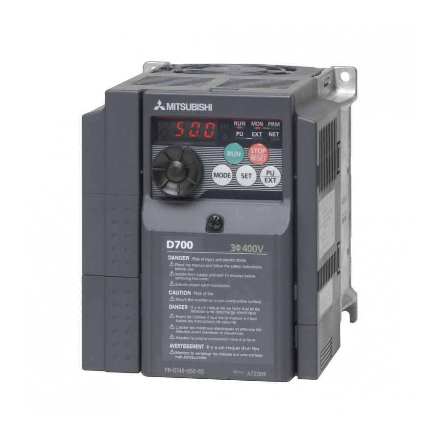
- Page 12 Explanation of the Operation Panel The operation panel cannot be removed from the inverter. Operating status display Operation mode indication Lit or flicker during inverter operation. ∗ PU: Lit to indicate PU operation mode. ∗ On: Indicates that forward rotation EXT: Lit to indicate External operation mode.
- Page 13 Basic operation of the operation panel Operation mode switchover At powering ON (External operation mode) PU Jog operation mode (Example) PU operation mode Value change and frequency flicker. (output frequency monitor) Frequency setting has been written and completed!! STOP Output current monitor Output voltage monitor Display the Parameter setting mode...
- Page 14 Explanations of Parameter unit Parameter unit (FR-PU07), parameter unit with battery pack (FR-PU07BB(-L) (available soon)) The parameter unit is a convenient tool for inverter setting Description such as direct input method with a numeric keypad, Use for parameter setting operation status indication, and help function. Press to choose the parameter setting mode.
-
Page 15: Parameter List
Parameter List For simple variable-speed operation of the inverter, the initial setting of the parameters may be used as they are. Set the necessary parameters to meet the load and operational specifications. Parameter setting, change and check can be made from the operation panel. - Page 16 Extended mode parameter REMARKS indicates simple mode parameters. The shaded parameters in the table allow its setting to be changed during operation even if "0" (initial value) is set in Pr. 77 Parameter write selection. Minimum Func- Initial Customer Parameter Name Setting Range Setting...
- Page 17 Minimum Func- Initial Customer Parameter Name Setting Range Setting tion Value Setting Increments Second acceleration/deceleration time 0 to 3600s 0.1s 5/10s ∗2 Second deceleration time 0 to 3600s, 9999 0.1s 9999 Second torque boost 0 to 30%, 9999 0.1% 9999 Second V/F (base frequency) 0 to 400Hz, 9999 0.01Hz...
- Page 18 Minimum Func- Initial Customer Parameter Name Setting Range Setting tion Value Setting Increments PID control automatic switchover 0 to 400Hz, 9999 0.01Hz 9999 frequency PID action selection 0, 20, 21, 40 to 43 PID proportional band 0.1 to 1000%, 9999 0.1% 100% PID integral time...
- Page 19 Minimum Func- Initial Customer Parameter Name Setting Range Setting tion Value Setting Increments 0, 1, 3, 4, 7, 8, 11 to 16, 25, 26, 46, 47, 64, 70, 80, 90, 91, 93, 95, 96, 98, 99, 100, 101, 103, RUN terminal function selection 104, 107, 108, 111 to 116, 125, 126, 146, 147, 164, 170, 180,...
- Page 20 Minimum Func- Initial Customer Parameter Name Setting Range Setting tion Value Setting Increments Communication operation command 0, 1 source Communication speed command 0, 1, 2 source Communication startup mode selection 0, 1, 10 Communication EEPROM write 0, 1 selection Communication error count —...
- Page 21 Minimum Func- Initial Customer Parameter Name Setting Range Setting tion Value Setting Increments Free parameter 1 0 to 9999 9999 Free parameter 2 0 to 9999 9999 Cumulative power monitor digit shifted — 0 to 4, 9999 9999 times FM terminal calibration —...
-
Page 22: Protective Functions
Protective Functions When a fault occurs, the inverter trips and the PU display automatically changes to any of the following fault or alarm indications. Function Name Description Display Operation panel lock Appears when operation was tried during operation panel lock. Password locked Appears when a password restricted parameter is read/written. -
Page 23: Option List
Option and Peripheral Devices Option list By fitting the following options to the inverter, the inverter is provided with more functions. Applicable Name Type Applications, Specifications, etc. Inverter FR-PU07 Shared among Parameter unit (8 languages) Interactive parameter unit with LCD display FR-PU04 all models Shared among... - Page 24 Peripheral devices/cable size list Magnetic Moulded Case Circuit Breaker (MCCB) ∗1 HIV Cables, or Earth Leakage Current Breaker (ELB) ∗2 Contactor (MC) Reactor ∗3 etc. (mm Motor ∗5 Reactor connection Reactor connection Inverter type Output (kW) R/L1, Without With Without With S/L2, U, V, W...
- Page 25 Selecting the rated sensitivity current for the earth leakage current breaker When using the earth leakage current breaker with the Example inverter circuit, select its rated sensitivity current as follows, × 5m × 60m 5.5mm 5.5mm independently of the PWM carrier frequency. Noise Breaker designed for harmonic and surge suppression filter...
-
Page 26: Precautions For Use Of The Inverter
Precautions for Operation/Selection Precautions for use of the inverter Installation Avoid hostile environment where oil mist, fluff, dust particles, Safety Precautions etc. are suspended in the air, and install the inverter in a clean To operate the inverter correctly and safely, be sure to read the place or put it in an ingress-protected "enclosed"... - Page 27 Precautions for selection Power transfer mechanism (reduction gear, belt, chain, etc.) Inverter capacity selection When an oil-lubricated gear box, speed change/reduction gear When operating a special motor or more than one motor in or similar device is used in the power transfer system, note that parallel with a single inverter, select the inverter capacity so that continuous operation at low speed only may deteriorate oil 1.1 times the total rated motor current is less than the rated...
- Page 28 Precautions for Peripheral Device Selection Installation and selection of moulded Measuring instrument on the output case circuit breaker side Install a moulded case circuit breaker (MCCB) on the power When the inverter-to-motor wiring length is large, especially in the receiving side to protect the wiring of the inverter input side. For 400V class, small-capacity models, the meters and CTs may MCCB selection, refer to page 25 since it depends on the inverter generate heat due to line-to-line leakage current.
- Page 29 Earth (Ground) Leakage currents When the inverter is run in the low acoustic noise mode, more Capacitances exist between the inverter I/O cables, other cables leakage currents occur than in the non-low acoustic noise mode and earth and in the motor, through which a leakage current flows. due to high-speed switching operation.
-
Page 30: Harmonic Suppression Guideline
Harmonic suppression guideline For compliance to "Harmonic suppression guideline of the transistorized inverter (input current of 20A or less) for consumers Harmonic currents flow from the inverter to a power receiving point other than specific consumers" published by JEMA. via a power transformer. The harmonic suppression guideline was Input established to protect other consumers from these outgoing Target... - Page 31 FR-D700 Series Specification Difference List Item Japanese Specification NA Specification EC Specification CHT Specification FR-D720-0.1K to 7.5K FR-D720-008 to 318-NA FR-D740-0.4K to 7.5K FR-D740-012 to 160-NA FR-D740-012 to 160-EC FR-D740-0.4K to 7.5K-CHT Applicable Capacity FR-D720S-0.1K to 2.2K FR-D720S-008 to 100-NA FR-D720S-008 to 100-EC FR-D720S-0.1K to 2.2K-CHT...
- Page 32 Warranty 1. Gratis warranty period and coverage [Gratis warranty period] Note that an installation period of less than one year after installation in your company or your customer's premises or a period of less than18 months (counted from the date of production) after shipment from our company, whichever is shorter, is selected.
- Page 33 ASEAN FA Center MITSUBISHI ELECTRIC AUTOMATION, INC. MITSUBISHI ELECTRIC ASIA PTE, LTD. 500 Corporate Woods Parkway, Vernon Hills, IL60061 U.S.A 307 Alexandra Road #05-01/02, Mitsubishi Electric Building, TEL. +1-847-478-2100 FAX. +1-847-478-0327 Singapore 159943 TEL. +65-6470-2480 FAX. +65-6476-7439 Taiwan FA Center Hong Kong FA Center SETSUYO ENTERPRISE CO., LTD.
Need help?
Do you have a question about the FR-D700 and is the answer not in the manual?
Questions and answers