Table of Contents
Advertisement
Quick Links
PSG
250, de Copenhague, Saint-Augustin-de-Desmaures
(Quebec), Canada G3A 2H3
After-sale service: 418-908-8002
E-mail:
tech@sbi-international.com
Installation and operating instructions
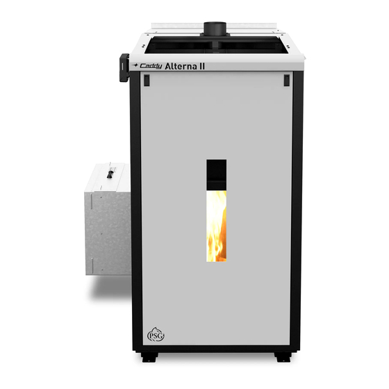
for the CADDY ALTERNA II (PF09010)
pellet furnace
READ THIS MANUAL THOROUGHLY
BEFORE OPERATING THE FURNACE
CERTIFIED ACCORDING TO CAN/CSA B366.1, UL391,
CAN/CSA C22.2 NO.236, UL 1995 by an accredited laboratory.
FURNACE MODELS INCLUDED IN THIS MANUAL
CADDY ALTERNA II PELLET AND 15 kW/20 kW
COMBINATION FURNACE
CONGRATULATIONS!
You have purchased one of the finest pellet or combination furnaces available
on the market. We are confident that your furnace will provide years of comfort
and safe operation.
Please keep this document for future references and quick service
This manual is available for free download on the manufacturer's web site. It is a
copyrighted document. Re-sale is strictly prohibited. The manufacturer may update this
manual without prior notice and cannot be held responsible for problems, injuries, or
damages arising out of the use of information contained in any manual obtained from
unauthorized sources.
45816A
Printed in Canada
16-11-2017
Advertisement
Table of Contents

Related Manuals for PSG CADDY ALTERNA II


Summary of Contents for PSG CADDY ALTERNA II
- Page 1 CERTIFIED ACCORDING TO CAN/CSA B366.1, UL391, CAN/CSA C22.2 NO.236, UL 1995 by an accredited laboratory. FURNACE MODELS INCLUDED IN THIS MANUAL CADDY ALTERNA II PELLET AND 15 kW/20 kW COMBINATION FURNACE CONGRATULATIONS! You have purchased one of the finest pellet or combination furnaces available on the market.
- Page 2 SAFETY PRECAUTIONS • • Do not operate your furnace if you smell Keep foreign objects out of the hopper. smoke coming from it. Turn it off, monitor it, and call your dealer. • • Never use gasoline, gasoline-type lantern Do not throw this manual away. This fuel, kerosene, charcoal lighter fluid, or similar manual important...
-
Page 3: Table Of Contents
GENERAL INFORMATION ALTERNA II (PF09010).................... 7 APPLIANCE PERFORMANCE ........................7 GENERAL FEATURES ..........................8 CADDY ALTERNA II TECHNICAL DATA ......................8 GENERAL TECHNICAL DATA........................9 ELECTRICAL INFORMATION – PELLET FURNACE AND ELECTRICAL ELEMENT ......... 9 TECHNICAL DATA – OTHER COMPONENTS ..................9 3.2.1... - Page 4 5.15 INSTALLATION OF AN AIR-CONDITIONING UNIT ................... 37 5.16 HEATPUMP INSTALLATION ........................38 5.17 ADD-ON INSTALLATION ..........................40 GENERAL INFORMATION ..........................41 OPERATION WARNINGS, CAUTIONS AND RECOMMENDATIONS ............41 COMBUSTIBLE ............................43 6.2.1 PROPER FUEL ............................43 6.2.2 WHERE TO STORE BAGS OF PELLETS ..................... 43 CONFIGURATION AND OPERATING INSTRUCTIONS ...................
- Page 5 24V ADDITIONAL EQUIPMENT ....................... 104 15.5 AIR CONDITIONING DAMPER ......................... 104 15.6 HUMIDIFIER ............................. 105 15.7 HEAT PUMP .............................. 105 WHY PURCHASE THROUGH AN AUTHORIZED PSG DEALER? ..............106 PSG LIMITED LIFETIME WARRANTY (REGULAR) ....................107 PSG LIMITED LIFETIME WARRANTY (PRIVILEGE) ....................108...
-
Page 6: Pellet Or Pellet/Electric Combination Furnaces
1 PELLET OR PELLET/ELECTRIC COMBINATION FURNACES The Caddy Alterna II furnace was tested using the guidelines of the CSA B415.1-10 Standard. To optimize the efficiency of your furnace, here are a few advice you should follow when installing or operating your Caddy Alterna II. -
Page 7: General Information Alterna Ii (Pf09010)
2 GENERAL INFORMATION ALTERNA II (PF09010) APPLIANCE PERFORMANCE ☨ Fuel type Wood Pellet (Premium grade or better) Recommended heating area 600 to 3,000 ft (56 to 279 m Hopper capacity 240 lb (90 kg) Maximum burn time 200 h Maximum heat input rate 101,000 BTU/h (29.6 kW) Overall heat output rate (min. -
Page 8: General Features
Canada, a mobile home is a dwelling for which the manufacture and assembly of each component is completed or substantially completed prior to being moved to a site for installation on a foundation and connection to service facilities and which conforms to the CAN/CSA-Z240-MH standard. 3 CADDY ALTERNA II TECHNICAL DATA CADDY ALTERNA II 56 ¼”... -
Page 9: General Technical Data
GENERAL TECHNICAL DATA TEMP MODEL DIRECT DRIVE THEORETICAL STATIC PRESSURE FILTER VAR. INPUT FLOW MOTOR SPEED (CFM) (PELLET) MIN. MAX. IN.W.C. 16” x 20” X 1” CADDY 1/2HP 1650 100,000 G-10 ALTERNA II Class 2 *INPUT ENERGY POTENTIAL PILOT MODE 10 000 BTU SPEED 1 50 000 BTU... -
Page 10: Odor From The Paint
ODOR FROM THE PAINT It is normal that smoke and odors emanate from the unit when you first light it. This is due to the paint curing process. It is recommended to burn the unit at a high rate and ventilate the furnace room and the building until the odors disappear. -
Page 11: Glass Specifications
4.7.1 GLASS SPECIFICATIONS The glass is made of 3/16” (5 mm) thick Pyroceram. You can purchase a replacement glass from your PSG dealer. ASH DRAWER Your furnace is equipped with an ash drawer to collect ashes produced by the combustion of pellets. The drawer must not be left open during combustion as this may cause ash dispersion through the ductwork. -
Page 12: Hopper Removal
5.1.1 HOPPER REMOVAL 1. Remove the screws (8) located at the bottom of the hopper. Then, slightly unscrew the vertical panel screws (4). 2. Disconnect hopper switch’s connector removing right side panel to access the connector. 3. After bottom screws are removed and the vertical panel screws are slightly... -
Page 13: Blower Assembly Removal
5.1.2 BLOWER ASSEMBLY REMOVAL The blower removal is done in three steps: Step #1: Remove the covers Remove the blower box and the feed motor covers removing the screws (11). Once all the screws are removed, slide the covers assembly towards the back to remove it. - Page 14 Step #2: Unplug electrical wires and rubber tube. Unplug the quick connect (A) and the rubber tube (B) (rubber tube must be put back on the right sensor side). Unplug the four pellet feeding motors wires (C). Step #3: Unscrew the blower box. Unscrew the screws located on each side of the blower box and the four screws located on the front.
-
Page 15: Unit Location And Fixation To The Floor
UNIT LOCATION AND FIXATION TO THE FLOOR The furnace must be installed where outside air supply is sufficient for proper combustion. In airtight houses or in certain local codes, it might be necessary to install an outside air intake (see Section 5.8: Combustion Air). Once you have determined the location of the furnace and that clearances to combustible materials are respected, it is highly recommended to secure the unit to the floor to prevent it from tipping backwards due to the weight of hopper full of pellets. -
Page 16: Hopper's Lid Opening
HOPPER’S LID OPENING The standard hopper’s opening is from the back to the front. However, it is possible to change the opening direction of the hopper’s lid to facilitate the pellet filling of the hopper depending on the different ducts installation (chimney, fresh air return, fresh air inlet, etc.). -
Page 17: Clearances To Combustible Materials
CLEARANCES TO COMBUSTIBLE MATERIALS N.B. This appliance must be installed according to the instructions on the unit’s certification label. DO NOT USE MAKESHIFT MATERIALS OR COMPROMISES IN THE INSTALLATION OF THIS UNIT. The furnace can be installed on a combustible floor. However, a non-combustible floor protector must cover all surfaces underneath the furnace. -
Page 18: Floor Protection
VALUES (B) AND (C) CAN BE INVERTED DEPENDING ON THE POSITION OF THE COMBUSTIBLE WALL. VALUE (C) MEETS THE MINIMUM STANDARD REQUIREMENTS TO PERFORM MAINTENANCE SAFELY. HOWEVER, WE RECOMMEND A 30" CLEARANCE TO FACILITATE MAINTENANCE OR REPLACEMENT OF CERTAIN PARTS. 5.4.1 FLOOR PROTECTION If the floor is made of non-combustible material, no floor protector is required. -
Page 19: Clearances To Combustible Materials For The Chimney
PARALLEL INSTALLATION The installation of the Caddy Alterna II with another furnace using the same ductwork is not allowed in Canada. This type of installation is only allowed in the United States. The maximum BTU input of the existing oil, gas, or electric furnace should be equal or higher than the maximum BTU input of the furnace. - Page 20 • A backflow damper be installed to prevent air return in one or the other of the two furnaces and to ensure that hot air will flow into the house and will not return through the plenum of the other furnace.
-
Page 21: Series Installation
5.7.2 STANDARDS The Caddy Alterna II is certified for use with a chimney certified to UL 103 or ULC S629M and a chimney type vent certified to UL 641 or CAN/ULC-S-609 and ULC/ORD C441, with 4” inner diameter. In Canada, we recommend that you use a listed pellet vent that meets the CAN/ULC S-609 and ULC/ORD C441 Standards. -
Page 22: Installation Configurations
INSTALL VENT AT CLEARANCES SPECIFIED BY THE VENT MANUFACTURER. INSPECT AND CLEAN FLUES AND CHIMNEY REGULARLY 5.7.3 INSTALLATION CONFIGURATIONS A. HORIZONTAL INSTALLATION THROUGH WALL Description Wall Pass-Thru Wall Support Vertical Cap 90° Elbow 45° Elbow Termination... -
Page 23: Equivalent Vent Length (Evl)
NOTE: Follow the vent manufacturer’s instructions. 1. Position furnaces, adhering to clearances. 2. Locate position of the hole in the wall; since most furnaces are installed in a basement, make sure that the hole in the wall is located above ground level. You will need to go up vertically for a few feet, and then go horizontally toward the wall. -
Page 24: Horizontal And Vertical Vent Chart
Vertical lengths = (2’ + 3’ + 2’) X 0.5’ = 3.5’ EVL 90° elbow or "TE" = (2 x 5’) = 10’ EVL Horizontal lengths = (4’ + 2’) = 6’ EVL Total EVL = (3.5’ + 10’ + 6’) = 19.5’... -
Page 25: Permitted Termination Location
5.7.6 PERMITTED TERMINATION LOCATION Refer to NFPA 211 (USA) or CSA B365 (Canada) for rules for the distance of exit terminals from windows and openings. The exit terminal of a mechanical draft system, other than a direct vent appliance (2-in-1 exhaust and fresh air intake) shall be located in accordance with the following. - Page 26 United States: • Not Less than 36’’ (91 cm) above any forced air inlet located within 10 feet (305 cm); • Not Less than 48’’ (122 cm) below and horizontally from, or one foot (30 cm) above, any door, window or gravity air inlet into any building (See note below for Direct Vent System (2-in-1 Exhaust and fresh air intake));...
- Page 27 C. VERTICALLY INTO EXISTING CHIMNEY SYSTEM As an alternative, the 4” vent can be run inside existing chimney to termination. NOTE: Follow the vent manufacturer’s instructions. 1. Have the chimney inspected by a qualified chimney sweep or installer to determine its structural condition. 2.
-
Page 28: Combustion Air
The Caddy Alterna II is approved with a fresh air supply connected directly to the unit. Indirect method: in the case of a non-certified solid fuel unit for a direct connection with a source of new combustion air supply, new air is moved into a pipe located within 12 inches (300 mm) or less of the solid fuel unit, in order to ensure its proper operation;... -
Page 29: Air Return Ducting Support Installation
NOTE: It is recommended to install an outside air inlet with a diameter of at least 5 inches in the room where the heating appliance is installed (see drawing below). It is preferable to choose a wall which is not exposed to dominant winds, depending on the conditions surrounding your house. -
Page 30: Installing The Link Board Box And Electrical Wiring
5.10 INSTALLING THE LINK BOARD BOX AND ELECTRICAL WIRING Note: The installation instructions in this section apply to a location of the controls to the right or to the left of the furnace. The most accessible side is preferable to facilitate the connection of auxiliary equipment or for servicing. The components to be installed are supplied in the furnace hopper. - Page 31 Align the formings with link board screw holes on the side of the hopper. Replace the screw to secure the housing. Once installed, the link board must connected system with telecom wires. wires can be found in the top compartment of blower box.
- Page 32 Take the two wires and pass them through the cable grommet located on the same side where the link board housing is installed. Connect the two wires to their respective terminals. Once the wires are outside the furnace, run them along the back of the furnace and pass them through the bottom cable grommet of the link board...
-
Page 33: Installing The Lcd User Interface
Before putting the blower box cover back on, the furnace must be plugged to an 115V current source. To do that, remove three knockouts that allow the easiest connection depending on your installation. Join the power cord to the Neutral (N), Ground (F) and Line (L) terminals. -
Page 34: Hot Air Plenum Temperature Probe Connection (Rtd)
5.12 HOT AIR PLENUM TEMPERATURE PROBE CONNECTION (RTD) On the Caddy Alterna II, a RTD has to be installed on the side of the appliance using the support provided with the unit. In order to secure the RTD support, remove the two screws already secured to the furnace on the side where you have chosen to install the link board. -
Page 35: Wall Thermostat Wiring
5.13 WALL THERMOSTAT WIRING The furnace must be connected to a thermostat. You can use the one provided with the unit or use one that is already installed in your home. The thermostat must be installed on an inside wall and located where it is not likely to be affected by the draft coming from an air outlet. -
Page 36: Electrical Element Connection
If you want to put the furnace in circulation mode from the thermostat, use the following connection diagram: Once wired to the furnace, it is possible to verify the signals coming from the wall thermostat by going to the ‘’TROUBLESHOOT LINK’’ menu and going to page 1 as shown below. When a signal is sent from the thermostat, the circle corresponding to the signal should appear green. -
Page 37: Installation Of An Air-Conditioning Unit
This installation will provide the most efficient and safe operation of the air conditioning coil unit using the distribution blower of the Caddy Alterna II furnace during summer. In order to complete the installation of an air-conditioning unit, the thermostat must be a “heat/cool”... -
Page 38: Heatpump Installation
5.16 HEATPUMP INSTALLATION It is possible to pair a heat pump to the Caddy Alterna II to benefit both types of heating (electric and wood pellet). To determine the priority of the operation of these two modes of heating, you must go to Section 7.2.3: Prioritization heating sources. - Page 39 Note: If a heat pump is connected to the Caddy Alterna II, the electric element PA08570 (15 kW) or PA08580 (20 kW) must be installed to ensure an auxiliary heat source (for installation, see Section 5.14: Electrical element connection) For installation of air conditioning coil, refer to Section 5.15: Installation of an air-conditioning unit.
-
Page 40: Add-On Installation
Caddy Alterna II furnace link board. This way, when a heat signal is given to the existing furnace, the Caddy Alterna II furnace will receive the same signal which will tell it to stop. -
Page 41: General Information
6 GENERAL INFORMATION OPERATION WARNINGS, CAUTIONS AND RECOMMENDATIONS • KEEP THIS MANUAL FOR REFERENCE. • DURING THE FIRST FEW FIRES, YOUR FURNACE WILL EMIT AN ODOR AND A SMALL AMOUNT OF FUMES AS THE HIGH TEMPERATURE PAINT CURES OR BECOMES SEASONED TO THE METAL. MAINTAINING SMALLER FIRES WILL MINIMIZE THIS. - Page 42 • IT IS RECOMMENDED TO UNPLUG THE FURNACE WHEN IT’S NOT IN USE FOR A PROLONGED AMOUNT OF TIME (I.E. DURING SUMMER). SENSORS ON THE FURNACE ARE ACTIVATED BY HEAT AND COULD ACTIVATE THE FANS EVEN IF THE FURNACE IS NOT IN FUNCTION. •...
-
Page 43: Combustible
COMBUSTIBLE 6.2.1 PROPER FUEL Each type of pellet has its properties and will burn differently. The amount of ashes produced can also vary greatly. Conventional pellets are those ¼” or 5/16” in diameter and not over 1” long. Longer or thicker pellets will prevent proper pellet feed. -
Page 44: Lcd Touch Screen Controls, Operation And Configuration
The pellet control board is used to manage wood pellet combustion according to the parameters entered in the LCD interface: The LCD touch screen is used to operate the system. More precisely for: Choosing the maximum BTU input; Choosing the pilot mode lag time; Choosing the combustion parameters;... -
Page 45: Description Of Each Main Status Icon
7.1.2 DESCRIPTION OF EACH MAIN STATUS ICON: SYSTEM CONFIGURATION 7.2.1 SELECTING THE LANGUAGE AND TEMPERATURE SCALE (⁰F OR ⁰C) To select preferred language and temperature scale, go to the ‘’GENERAL’’ menu. You can choose between two languages, English or French and between °F or °C. Follow the tree structure below... -
Page 46: Options Selection
7.2.2 OPTIONS SELECTION Before entering the OPTIONS setting the wall thermostat must be on OFF position. To add options to your Alterna II furnace, you must first go to the sub-menu ‘’SELECTION’’ in the ‘’OPTION’’ menu to activate the different options desired. By default, no option is activated. To activate one or more options, you must press the box next to the desired option. -
Page 47: System Balancing
7.2.6 CHOOSING THE INPUT BTU Your Caddy Alterna II has an input that can reach up to 100,000 BTU. Since the efficiency of the furnace is 82%, the output can be calculated by multiplying the input by 0.82. In order to reduce cycling of the furnace, the BTU input can be adjusted by the installer based on the size of the house. -
Page 48: Unit Operation
UNIT OPERATION 7.3.1 ADJUSTING THE COMBUSTION LEVEL (HEAT OUTPUT) PLENUM 148°F Burn rate adjustment Burn rate The stove’s input range goes from 50,000 BTU to 100,000 BTU. To change combustion level, select the flame on the main page to display the “+” and “-” combustion level settings. icon Note: Input range may vary according to the type of pellets being used. -
Page 49: Selecting The Pilot Cycle
PILOT ADJUSTMENT (Pilot Settings Adjustment) The “PILOT ADJUSTMENT” will allow you to modify default settings by +5% for gear motor 1 and ±10% for combustion and exhaust fan, but will only apply during the pilot cycle: To restore default setting, select “DEFAULT”. COMBUSTION ADJUSTMENT (Fuel Quality Adjustment) The “COMBUSTION ADJUSTMENT”... -
Page 50: Start, Stop And Time Delay Parameters Adjustments
30 MINUTES OR 60 MINUTES The pilot cycle begins when temperature set on the thermostat is reached. It will last 30 or 60 minutes depending on the selected pilot cycle. If the thermostat does not call for heat before the end of the selected pilot cycle delay, the furnace will shut down and will need to go through the complete ignition cycle when the thermostat calls for heat again. -
Page 51: Purge Screw
7.3.6 PURGE SCREW At the end of the heating season or when necessary, it is possible to empty the auger screw as well as the remaining pellets in the hopper. First, empty the hopper as much as possible. Then, by pressing the ‘’SETTING’’ icon and pressing the ‘’PURGE SCREW’’... -
Page 52: General Operation And Advices
WARNING: DO NOT USE IF YOUR FURNACE PRESENTS ABNORMAL LEAKS FOLLOWING DETERIORATION OF GASKETS OR IF THE GLASS OF THE COMBUSTION CHAMBER DOOR IS BROKEN. DO NOT USE YOUR FURNACE WITHOUT GASKETS AROUND THE DOOR. LEAKS CAN LEAD TO OVERHEATING, OR IN A VERY TIGHTLY SEALED HOUSE, COULD CAUSE SMOKE IN THE HOUSE. SMOKE MAY CONTAIN CARBON MONOXIDE, WHICH IS A POISON. -
Page 53: Maintenance
If the fire gets uncontrollable due to an improper use or because the draft is too strong, follow the same procedure as in a chimney fire. LOCAL FIRE DEPARTMENT Phone number: ___________________________________ 9 MAINTENANCE MAINTENANCE OF THE HEAT EXCHANGER AND BAFFLE The heat exchanger is to be cleaned thoroughly at the end of each heating season. - Page 54 Then unscrew the two wing nuts to remove the access trap located above combustion chamber.
- Page 55 It is important to start from the top of the heat exchanger and finish at the bottom not to put back ashes where they have already been removed. Using the scraper, clean the six exchanger pipes. Using an ash vac will be the most efficient way to collect ashes that may have accumulated.
- Page 56 You will have access to the 2 clean out traps (B) and (C). Unscrew the two wing nuts on each clean out traps and remove them. ensure complete cleaning, completely remove the separator of the exchanger (A) and clean the back pipe of the exchanger.
-
Page 57: Cleaning The Baffle
Also open the trap on the right side (D) (see figure beginning of Section 9.1: Maintenance of the heat exchanger and baffle) to complete the cleaning. Be sure to put back the exchanger separator in place immediately after cleaning. The absence of the exchanger separator will result in a loss of performance of the furnace. -
Page 58: Venting System Maintenance
The baffle (B) will rotate on the spindle drop accumulated fly ash. Clean and reinstall the baffle. 1) To remove the baffle (for a replacement) pivot the lock plate (A) by 90°. When the baffle has ended its rotation, place the lock to its initial position. -
Page 59: Ash Removal And Vacuum Use
CAUTION: CLEANOUT OF THE HEAT EXCHANGER, FLUE PIPE AND CHIMNEY, IS ESPECIALLY IMPORTANT AT THE END OF THE HEATING SEASON TO MINIMIZE CORROSION DURING THE SUMMER MONTHS, CAUSED BY ACCUMULATED ASH. ASH REMOVAL AND VACUUM USE In order to remove ashes from the ash drawer, remove the front access panel of the furnace’s jacket, unscrew the wing nut, open the access door and remove the ash drawer. -
Page 60: Cleaning The Distribution Blower
CLEANING THE DISTRIBUTION BLOWER It is recommended to clean the distribution blower blades according to the maintenance schedule presented below. Access the blower by removing cap (or filter support) to the right of the blower housing. Use a brush to lift the dust of blades. -
Page 61: Maintenance Of The Pressure Switch Tap
High efficiency 2-ply, 3-ply, or 4-ply filter is recommended. Filter dimension Caddy Alterna II: 16” x 20” x 1” filter 9.11 DOOR GASKET MAINTENANCE It is important to maintain the door gasket in good condition. After a while, the gasket might sag; a door adjustment may then be required. -
Page 62: Recommended Maintenance Schedule
9.12 RECOMMENDED MAINTENANCE SCHEDULE Use this as a guide under average-use conditions. Weekly Twice a year Annually Components or after or after +/- 500 pounds +/- 2 tons per 4 tons of pellets Baffle Brush / Vacuum Burn Pot Brush / Vacuum Glass Clean Scrape &... -
Page 63: Validating Status
NOTE: IF YOU NEED TO CONTACT YOUR DEALER OR TECHNICAL SUPPORT, MAKE SURE TO HAVE THE MODEL OF YOUR APPLIANCE AND THE SERIAL NUMBER ON HAND. (THEY CAN BE FOUND ON THE CERTIFICATION LABEL INSIDE THE HOPPER LID). 10.1 VALIDATING STATUS When using your furnace, you can validate at any time, the status of any of the following components: Electronic components (low power rated) L-250A (security heat sensor) -
Page 64: Testing Components
WITH GREEN ICONS Pressure switch is closed. This condition is normal if the furnace is in operation. Pressure switch is open. This condition is normal if the furnace is OFF. WITH RED ICONS Pressure switch is closed. This condition is abnormal if the furnace is OFF. -
Page 65: Blocked Flue
NOTE: IF, AFTER PERFORMING ALL THE POSSIBLE SOLUTIONS MENTIONED IN THE FOLLOWING SECTION, YOU ARE STILL EXPERIENCING PROBLEMS WITH YOUR FURNACE, CALL YOUR LOCAL DEALER OR AFTER-SALE SERVICE AT 418-908-8002. YOU CAN ALSO WRITE AN EMAIL TO TECH@SBI- INTERNATIONAL.COM. ALL EMAILS ARE ANSWERED WITHIN A 24H DELAY. NOTE: IF YOU NEED TO CONTACT YOUR DEALER OR TECHNICAL SUPPORT, MAKE SURE TO HAVE THE MODEL OF YOUR FURNACE AND THE SERIAL NUMBER ON HAND. -
Page 66: No Fuel
10.3.2 NO FUEL COMBUSTION FAN FUSE THE COMBUSTION FAN FUSE BLEW UP RESET DETAILS ❖ The furnace ran out of pellets. Refill the hopper. Press on the button and then on the “ON/OFF” button . Your furnace will only restart when the cool down cycle is completed. ❖... -
Page 67: Failed Ignition
the heat at the exhaust. When the furnace is cold, check page 1 in the "TROUBLESHOOT FURNACE" menu if the temperature displayed on the line “EXAUST TEMP” displays a value equal to the ambient temperature in the room where the appliance is installed. If this is the case, turn on the furnace and check the same temperature display. -
Page 68: Defective Igniter Fuse
10.3.4 DEFECTIVE IGNITER FUSE ❖ The igniter is defective: Test the resistance (ohms, Ω) with a multimeter. If the value is near zero, replace the igniter and the G fuse (see Section 11.9: Access the fuses). ❖ The wiring harness shorted. Inspect the wiring and replace any defective wire and or connectors. Make sure the wires are not shorted to the furnace frame. -
Page 69: Unit Overheat
welds. Remove any foreign material that may have caused the jam. Inspect the auger housing for signs of damage such as burrs, rough spots, or grooves cut into the metal that could have caused a jam. Clean the auger housing thoroughly to remove all pellet dust. If the hopper’s rotary valve is jammed, empty the hopper’s pellet contents completely to access the top of the rotary valve. -
Page 70: Hopper Lid Open
NOTE: IF THE CODE APPEARS MORE THAN THREE TIMES, THE LCD SCREEN WILL LOCK ITSELF UP. THIS PELLET FURNACE IS EQUIPPED WITH MULTIPLE DEVICES TO ENSURE YOUR SAFETY. IF A WARNING ERROR CODE STOPS YOUR FURNACE ON SEVERAL OCCASIONS, IT IS MORE THAN LIKELY THAT THE FURNACE DOES NOT EXHAUST PROPERLY. -
Page 71: Power Loss
❖ The hopper lid safety switch is faulty or disconnected. Make sure that the switch wiring is properly connected. If it is, the hopper switch may be faulty. Verify the proper function of the safety switch (see Section 10.2: Testing Components). Replace if necessary. 10.3.8 POWER LOSS ❖... -
Page 72: Smoke Smell
❖ I/O communication error. The information coming from the I/O board is not read by the link board. It is possible that the telecommunication wire connecting the link board to the pressure board or the wire connecting the pressure board to the I/O board has a loose connection. Make sure that each end of those wires is well connected in their own terminals. -
Page 73: The Lcd Touch Screen Does Not Light-Up
Any defect must be repaired without delay using genuine PSG replacement parts. You can find a complete list of replacement parts in our website at www.caddyfurnaces.com. -
Page 74: The Auger Motor
11.3 THE AUGER MOTOR To replace the auger motor, first remove the current of the furnace. Then remove the screws from around the cover and remove it. Disconnect the power supply wires (B) of the motor to change. To remove the auger motor, you must loosen the motor’s screw axis (A). - Page 75 If you have to replace the gear motor 2, it is possible to do this without first removing the gear motor 1. The steps are the same: disconnect the two power supply wires (D), align the motor shaft screw (C) (using the furnace repair mode, if required, until the screw head is located in the Zone θ) and unscrew them.
-
Page 76: Auger Replacement
11.4 AUGER REPLACEMENT First, remove the top cover of the blower housing. Completely remove the two set screws of the bottom auger and remove the motor (see Section 11.3: The Auger motor). Then remove the furnace's jacket front panel, open the combustion chamber door and remove the burn pot. -
Page 77: Exhaust Blower Replacement
Unscrew the two screws from the auger holder (3) using a Torx T30 end piece. Finally, remove the auger by pulling it out of the furnace (4). It is possible that some residue remains in the auger tube making it more difficult to remove. If this is the case, turn the auger clockwise to release it. -
Page 78: Combustion Blower Replacement
11.6 COMBUSTION BLOWER REPLACEMENT To replace the combustion blower, remove the right panel of the furnace’s jacket. Open latch combustion blower support. Take out the combustion blower motor removing support positioning holes at the bottom of the part. Once the support out of its anchoring, disconnect blower... -
Page 79: Distribution Blower Replacement
11.7 DISTRIBUTION BLOWER REPLACEMENT To replace the furnace’s distribution blower, first remove two side panels of the blower housing (one on the back and the other on the side). Unplug the fan connector (A) from the power board. -
Page 80: Igniter Replacement
Remove the four bolts holding blower place. Pull the blower out by sliding it to the left or right side (opposite side of the air return support). 11.8 IGNITER REPLACEMENT Remove the furnace's jacket front panel open combustion chamber door. Unscrew the two screws that hold in place the igniter and the igniter support (see Detail (1)). -
Page 81: Access The Fuses
Slide the igniter tube (3) upward disconnect igniter connector (4). Once disconnected, lift the igniter to take it out of the combustion chamber. Align igniter connector in the igniter support hole to ease its removal. 11.9 ACCESS THE FUSES To access the fuses, remove the eight (8) screws located around the cover of the blower housing and remove it. - Page 82 Pellet I/O control board FUSE FONCTION AMPS BOARD MAIN FUSE 7.5A CONVECTION BLOWER COMBUSTION BLOWER EXHAUST BLOWER UPPER AUGER MOTOR #1 BOTTOM AUGER MOTOR #2 IGNITER Power board FUSE FONCTION AMPS POWER BOARD FUSE DISTRIBUTION FAN FUSE...
-
Page 83: Exploded Views And Replacement Parts
EXPLODED VIEWS AND REPLACEMENT PARTS... - Page 84 SECTION A SECTION B...
- Page 85 SECTION C SECTION D...
- Page 86 SECTION E SECTION F...
- Page 87 SECTION G SECTION H...
- Page 88 SECTION I SECTION J...
- Page 89 SECTION K SECTION L...
- Page 90 SECTION M SECTION N...
- Page 91 SECTION O...
- Page 92 HARNESS SECTION...
- Page 94 TELECOMMUNICATION WIRES SECTION...
- Page 98 IMPORTANT: THIS IS DATED INFORMATION. When requesting service or replacement parts for your furnace, please provide the model number and the serial number. We reserve the right to change parts due to technological upgrades or availability. Contact an authorized dealer to obtain any of these parts. Never use substitute materials. Use of non-approved parts can result in poor performance and safety hazards and will void your warranty.
- Page 99 Item Description 30485 WING NUT 1/4-20 X 1/2'' ZINC PLATTED PL67175 BAFFLE LATCH PL68582 BAFFLE SE68504 ASH DRAWER ASSEMBLY SE68571 ASH DRAWER ACCESS ASSEMBLY AC06000 SILICONE AND 1/2" X 8' BLACK DOOR GASKET REPLACEMENT KIT 30168 HINGE PIN 5/16 DIA. X 1 1/4" LONG 30416 WING NUT 3/8"-16 SE68536...
- Page 100 Item Description SE68532 HOPPER ASSEMBLY PL68615 HOPPER LID 44098 HOPPER LID SAFETY SWITCH PL68623 PROGRAMMED I/O PC BOARD PL44170 PRESSURE SENSOR 30408 ELECTRONIC BOARD CLIP 44013 FUSE 7.5A / 250V / 1/4" DIA. X 1 1/4'' LONG 44151 FUSE 5A / 250V (5 X 20) F1-CONV F5-EXHAUST F6-ACC 44150 FUSE 3A / 250V (5 X 20) F4-AUGER &...
-
Page 101: General Electric Diagram
13 GENERAL ELECTRIC DIAGRAM... -
Page 102: Wiring Diagram With Optional Electrical Element (Pa08570/Pa08580)
14 WIRING DIAGRAM WITH OPTIONAL ELECTRICAL ELEMENT (PA08570/PA08580) CADDY ALTERNA II PELLET/ELECTRIC COMBINATION FURNACE... -
Page 103: Link Board Options Connections
LINK BOARD OPTIONS CONNECTIONS 15.1 ELECTRICAL CONSUMPTION Your Caddy Alterna II furnace is able to supply electrical 24V current to control various options. The options that can be supported are described in the table below. The maximum available 24V current is 1.66 amps (transformer 24V @ 40VA). -
Page 104: Hot Water Option
15.3 HOT WATER OPTION 15.4 24V ADDITIONAL EQUIPMENT 15.5 AIR CONDITIONING DAMPER... -
Page 105: Humidifier
15.6 HUMIDIFIER 15.7 HEAT PUMP... -
Page 106: Why Purchase Through An Authorized Psg Dealer
Given the importance of the installation, PSG recommends that it be carried out by a professional certified in the Building Code so that the furnace delivers its full potential. This is why PSG offers an additional warranty that covers the cost of labor if your furnace has been purchased through an authorized PSG dealer. -
Page 107: Psg Limited Lifetime Warranty (Regular)
90 days *Pictures required **Subject to limitations above. Shall your unit or a component be defective, contact immediately your PSG dealer. Prior to your call make sure you have the following information necessary to your warranty claim treatment: • •... -
Page 108: Psg Limited Lifetime Warranty (Privilege)
All parts replaced under the warranty. *Pictures required **Subject to limitations above. Shall your unit or a component be defective, contact immediately your PSG dealer. Prior to your call make sure you have the following information necessary to your warranty claim treatment: •...
Need help?
Do you have a question about the CADDY ALTERNA II and is the answer not in the manual?
Questions and answers