Table of Contents
Advertisement
Quick Links
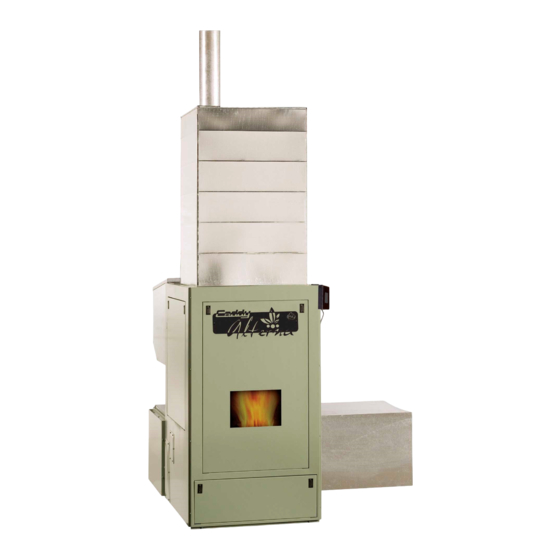
Installation and operating instructions
for the CADDY ALTERNA pellet furnace
CERTIFIED ACCORDING TO CAN/CSA B366.1 M91,UL391 4
FURNACE MODELS INCLUDED IN THIS MANUAL
CADDY ALTERNA PELLET AND 15kW/20kW COMBINATION
Read these instructions carefully before installing and operating
You have purchased one of the finest pellet or combination furnaces
available on the market. We are confident that your furnace will provide
Please keep this document for future references and quick service
This manual is available for free download on the manufacturer's web site. It is a
copyrighted document. Re-sale is strictly prohibited. The manufacturer may update this
manual from time to time and cannot be responsible for problems, injuries, or damages
arising out of the use of information contained in any manual obtained from
unauthorized sources.
Printed in Canada
READ THIS MANUAL THOROUGHLY
BEFORE OPERATING THE FURNACE
CAN/CSA C22.2 NO.236-05, UL 1995 3
FURNACE
your furnace.
CONGRATULATIONS!
years of comfort and safe operation.
250, de Copenhague, Saint‐Augustin‐de‐Desmaures
(Quebec), Canada G3A 2H3
Tel: (418) 878‐3040
Fax: (418) 878‐3001
TH
EDITION 2006,
RD
EDITION 2003
PSG
45406A
07-11-2011
Advertisement
Table of Contents

Related Manuals for PSG CADDY ALTERNA


Summary of Contents for PSG CADDY ALTERNA
- Page 1 PSG 250, de Copenhague, Saint‐Augustin‐de‐Desmaures (Quebec), Canada G3A 2H3 Tel: (418) 878‐3040 Fax: (418) 878‐3001 Installation and operating instructions for the CADDY ALTERNA pellet furnace READ THIS MANUAL THOROUGHLY BEFORE OPERATING THE FURNACE CERTIFIED ACCORDING TO CAN/CSA B366.1 M91,UL391 4 EDITION 2006, CAN/CSA C22.2 NO.236-05, UL 1995 3 EDITION 2003...
- Page 2 SAFETY PRECAUTIONS Do not operate your furnace if you smell Keep foreign objects out of the hopper. smoke coming from it. Turn it off, monitor it, and call your dealer. Never use gasoline, gasoline-type lantern Do not throw this manual away. This fuel, kerosene, charcoal lighter fluid, or similar manual has important operating and liquids to start or “freshen up”...
-
Page 3: Table Of Contents
TABLE OF CONTENTS PELLET OR PELLET/ELECTRIC COMBINATION FURNACES ............. 6 1. SAFETY RULES ............................. 6 GENERAL REQUIREMENTS ...................... 6 ODOUR FROM THE PAINT ......................6 ASH DISPOSAL ..........................6 CREOSOTE BUILD-UP AND REMOVAL .................. 7 SOOT AND FLY ASH ........................7 SMOKE DETECTOR ........................ - Page 4 AUGER MOTOR ......................... 48 GENERAL WIRING DIAGRAM ....................49 WIRING DIAGRAM WITH OPTIONAL ELECTRICAL ELEMENT ........52 CADDY ALTERNA TECHNICAL DATA ..................53 GENERAL TECHNICAL DATA ....................53 TECHNICAL DATA – ELECTRICAL ELEMENT ..............53 TECHNICAL DATA – OTHER COMPONENTS ............... 53...
- Page 5 IMPORTANT NOTE: THE INSTALLATION OF THIS CENTRAL HEATING SYSTEM MUST BE PERFORMED BY A QUALIFIED TECHNICIAN. PSG RESERVES ITSELF THE RIGHT TO VOID ITS WARRANTY OR DENY TECHNICAL ADVICE IF THE FURNACE HAS NOT BEEN SOLD OR INSTALLED BY A PROFESSIONAL.
-
Page 6: Pellet Or Pellet/Electric Combination Furnaces
PELLET OR PELLET/ELECTRIC COMBINATION FURNACES The Caddy Alterna furnace was tested using the guidelines of the EPA Standard. To optimize the efficiency of your furnace, here are a few advices you should follow when installing or operating your Caddy Alterna. -
Page 7: Creosote Build-Up And Removal
CREOSOTE BUILD-UP AND REMOVAL When fuel is burned slowly, it produces tar and other organic vapours which, when combined with moisture, form creosote. The creosote vapours condensate in a relatively cool chimney flue. As a result, creosote residues accumulate on the flue lining. When ignited, creosote produces an extremely hot fire inside the chimney. -
Page 8: Glass Specifications
1.7.1 GLASS SPECIFICATIONS The glass is made of 3/16” (5mm) thick Pyroceram. You can purchase a replacement glass from your PSG dealer. ASH DRAWER Your furnace is equipped with an ash drawer to collect ashes produced by the combustion of pellets. This drawer must not be left open during combustion as this may cause ash dispersion through the ductwork. - Page 9 Remove the screws from the hopper support (keep the screws). Loosen screws inside the hopper. Lift it and pull it backwards.
-
Page 10: Blower Assembly Removal
2.1.2 BLOWER ASSEMBLY REMOVAL The blower removal is done in two steps: Step #1: Disconnect the silicone tube and electrical wires that are connected to the pump. The pump is located on the right side of the furnace’s blower assembly. Once the silicone tube and wires are disconnected, make sure that you get them out of the blower assembly. - Page 11 Step #2: Remove the screws around the blower assembly.
-
Page 12: Unit Location And Fixation To The Floor
UNIT LOCATION AND FIXATION TO THE FLOOR The furnace must be installed where outside air supply is sufficient for proper combustion. In airtight houses, it might be necessary to install an outside air intake (see COMBUSTION AIR SECTION #2.6). It is highly recommended that the unit be secured to the floor in order to prevent any situation where it could tip toward the back. -
Page 13: Clearances To Combustible Materials
CLEARANCES TO COMBUSTIBLE MATERIALS 2.3.1 CLEARANCES TO COMBUSTIBLE MATERIALS FOR THE UNIT N.B. This appliance must be installed according to the instructions on the unit’s certification label. DO NOT USE MAKESHIFT MATERIALS OR COMPROMISES IN THE INSTALLATION OF THIS UNIT. CEILING CEILING 60"... - Page 14 N.B. THE SIZE OF THE AIR RETURN DUCT SHOULD BE AT LEAST EQUAL TO THE SIZE OF THE COLD AIR PLENUM OPENING. The air return duct can be installed at zero clearance with the ceiling. FIRST 5 FEET OF DUCT INCLUDING 2”...
-
Page 15: Parallel Installation
PARALLEL INSTALLATION The installation of the Caddy Alterna with another furnace using the same ductwork is not allowed in Canada. This type of installation is only allowed in the United States. Ideally, the maximum BTU input of the existing oil, gas, or electric furnace should be equal or higher than the maximum BTU input of the wood furnace. -
Page 16: Venting
VENTING The Caddy Alterna is certified for use with a chimney certified to UL-103 or ULC S629M and a chimney type vent certified to UL-641 or ULC-S-609-M89 and ULC/ORD C441-M90, with 4” inner diameter. In Canada, we recommend that you use a listed pellet vent that meets the ULC S-609-M89 and ULC/ORD C441-M90 Standards. For the United States, we recommend that you use a listed pellet vent that meets the UL-641, 7 edition Standard. This unit can be... -
Page 17: Installation Configurations
INSTALLATION CONFIGURATIONS A. HORIZONTALLY THROUGH WALL VERTICAL ROOF VENT 90 DEGREE ELBOW FOLLOW CHIMNEY OR 45 DEGREE ELBOW FOLLOW CHIMNEY OR VENT MANUFACTURER'S VENT MANUFACTURER'S INSTRUCTIONS INSTRUCTIONS TERMINATION COLLAR WALL WALL THIMBLE THIMBLE WALL STRAP WALL STRAP CLEAN OUT CLEAN OUT MIN. - Page 18 NOTE: Follow the vent manufacturer’s instructions. 1. Position furnaces, adhering to clearances. 2. Locate position of hole in wall; since most furnaces are installed in a basement, make sure that the hole in the wall is located above ground level. You will need to go up vertically for a few feet, and then go horizontally toward the wall.
- Page 19 Important: termination’s location: a) not less than 3 feet above any forced air inlet located within 10 feet; b) not less than 4 feet below or horizontally from, or one foot above, any door, window or gravity air inlet into any building; c) not less than two feet from an adjacent building and not less than 7 feet above grade when located adjacent to a public walkway.
- Page 20 C. VERTICALLY INTO EXISTING CHIMNEY SYSTEM As an alternative, the 4” vent can be run inside existing chimney to termination. NOTE: Follow the vent manufacturer’s instructions. 1. Have the chimney inspected by a qualified chimney sweep or installer to determine its structural condition. 2.
-
Page 21: Horizontal And Vertical Vent Chart
APPENDIX A HORIZONTAL AND VERTICAL VENT CHART If you plan your venting Possible Vertical system configuration on vent length this chart, your wall or roof termination should be within the grid. Possible Horizontal vent length (feet) Let’s imagine an installation consisting of a 4-feet vertical rise, a 90-degree elbow, followed by a 7-feet horizontal run through the wall, ending with a termination cap. -
Page 22: Combustion Air
COMBUSTION AIR When the furnace and the chimney are completely cold, it may be necessary to provide fresh air by opening a door or a window for a few minutes while lighting the fire. Take note that a house constructed or renovated in order to be airtight may lack the amount of fresh air necessary for the proper combustion of a solid-fuel heating appliance. -
Page 23: Cold Air Ducting Support Installation
NOTE: It is recommended to install an outside air inlet with a diameter of at least 5 inches in the room where the heating appliance is installed (see drawing below). It is preferable to choose a wall which is not exposed to dominant winds, depending on the conditions surrounding your house. -
Page 24: Installing Limiting Board
INSTALLING THE PELLET CENTRAL PROCESSING UNIT (PELLET CPU) Different locations can be chosen to install the pellet central processing unit (Pellet CPU). First, choose the location to install the pellet central processing unit (Pellet CPU). It will be located on the left or right side of the furnace.Then, you must choose to install the pellet central processing unit (Pellet CPU) directly on the hopper (option #1) or on the bracket. - Page 25 SCREWS ARE INSTALLED ON THE FURNACE SCREWS ARE INCLUDED WITH MANUAL Option #2 Screws already installed GROUND AC LINE AC COMMON PELLET CPU WHITE WIRE CONNECT THE WHITE WIRES TOUCHSCREEN LCD WITH BLACK STRIPES BLACK WIRES WITH WHITE STRIPES CONNECTING TO THE LIMITING BOARD THE WIRES COME FROM...
-
Page 26: Installing The Lcd User Interface
INSTALLING THE LCD USER INTERFACE The LCD user interface (touchscreen) is used for the system’s operation. In order to secure it, you need to install the LCD user interface support using two screws (two holes are designed for this installation on the furnace). The LCD user interface support and the two screws are supplied with the owner’s manual. -
Page 27: Temperature Probe Connection (Rtd)
TEMPERATURE PROBE CONNECTION (RTD) On the Caddy Alterna, a RTD has to be installed on the side of the appliance using the support provided with the unit. In order to secure the RTD support, remove the two screws already secured to the furnace on the side where you have chosen to install the pellet central processing unit (Pellet CPU). -
Page 28: Electrical Element Connection
2.11 ELECTRICAL ELEMENT CONNECTION The following instructions do not supersede the local code. The electrical element must be connected to the pellet central processing unit (Pellet CPU) (see WIRING DIAGRAM). For security reasons, the electrical element has a manual reset thermostatic sensor that is located inside the electrical unit. -
Page 29: Fan Control
INSTALLATION OF AN AIR CONDITIONING UNIT The Caddy Alterna pellet furnace has been tested with an optional air conditioning unit. If this option is chosen, we recommend an installation as per the graphic provided below. This installation will provide the most efficient and safe operation of the air conditioning unit using the distribution blower of the Caddy Alterna furnace during summer. - Page 30 DAMPER A/C COIL DAMPER Recommended Installation with an AC unit Note : It is important to apply the sticker to the furnace and have the installer fill all fields. The last step consists of installing the coil handle supplied with the owner’s manual to the handle rod.
-
Page 31: Configuration And Operating Instructions
CONFIGURATION AND OPERATING INSTRUCTIONS Before you configure your system and learn how to operate it, it is important to note that your Caddy Alterna is equipped with 3 main electronic components: the main control board, the pellet central processing unit (Pellet CPU), and the LCD user interface. -
Page 32: Limiting Board
PELLET CENTRAL PROCESSING UNIT (PELLET CPU) On the Caddy Alterna furnace, a new electronic control was developed. This system is more polyvalent. All connections are done from the the pellet central processing unit (Pellet CPU). There are connector ports available for all components and options. -
Page 33: The Speeds
3.3.1 THE SPEEDS Your furnace is equipped with a 4-speed blower. Using the pellet central processing unit (Pellet CPU), we have created 6 functional speeds. Refer to Table 2 below for the various speed configurations. Table 2 – The Speeds Speed Corresponding data CFM*... -
Page 34: Cool Mode (Air Conditioning)
which will change to pilot mode. When the temperature returns to a safe level, the blower speed gradually returns to the speed required to maintain the BEP. Programming Make sure that your wall thermostat is well connected to the pellet central processing unit (Pellet CPU). The main thermostat must be connected to the “WOOD MECH”... -
Page 35: Manu (Manual Heating)
In the MODE menu, select CIRC by pushing the SELECT button. Then, using the arrows buttons, choose from the different selections: TEMP, UNIT, or FAN. Consult the “Selections” section in order to obtain a compete definition of the terms TEMP, UNIT, and FAN. When your choice is made, press SELECT. - Page 36 Using the arrows, increase or decrease the blower speed. You can choose from six preselected speeds. This selection is very important for the modes COOL, MANU, or CIRC. There is a choice of 6 different speeds. Under the COOL mode, the speed selected is the speed at which the distribution blower will work when a cooling demand will be sent by the thermostat.
-
Page 37: Lcd User Interface - Operation And Configuration
LCD USER INTERFACE – OPERATION AND CONFIGURATION Manual mode main page Thermostat mode main page Indicates that the furnace status is on manual mode = Indicates that the furnace status is on thermostat mode. The green waves indicate that the thermostat is on demand. The waves will disappear once the desired temperature is reached. Indicates the flue temperature = Indicates the BTU setting. -
Page 38: Operation Tree
OPERATION TREE Selects the language displayed on the LCD interface (french, english, or spanish) Selects the pilot mode (30 minutes, 45 minutes, always This is a non-interactive page. It will help the user Selects scale Menu Screen troubleshoot the unit if temperature displayed on the needed (verifies... -
Page 39: Choosing The Maximum Input (Btu)
3.5.1 CHOOSING THE MAXIMUM INPUT (BTU) Your Caddy Alterna has an input that can reach up to 120,000 BTU. Since the efficiency of the furnace is 81.2%, the output can be calculated by multiplying the input by 0.812. In order to reduce cycling of the furnace, the BTU input can be adjusted by the installer based on the size of the house. -
Page 40: View Statistics
Pellets made of wood and hay will produce more ash than straight wood pellets. The wood and hay pellets that have been tested in your Caddy Alterna consisted of 1/3 hay and 2/3 wood. Make sure that any wood and hay pellets you put in your Caddy Alterna respect that mix (+/- 10%). -
Page 41: Early Signs Of An Overfired Furnace
3.6.2 EARLY SIGNS OF AN OVERFIRED FURNACE If you see a lazy, very high orange flame inside the firebox, it may be a signed thatyour furnace is overfired and getting too hot. Under normal conditions, the flame should be about 12 inches high and it should be lively. It should have a bright, yellow color. -
Page 42: Maintenance
4. MAINTENANCE MAINTENANCE OF THE EXCHANGERS AND BLOWER HOUSING The heat exchangers are to be cleaned thoroughly at the end of each heating season. During the summer air is more humid with minimal natural flow in the furnace, in these conditions, remaining creosote and/or soot in the exchangers will produce an acid that will accelerate the corrosion process and will perforate the steel prematurely, which in return, would not be covered under this warranty. -
Page 43: Venting System Maintenance
VENTING SYSTEM MAINTENANCE REGULARLY EXAMINE THE FLUE PIPES, THE JOINTS, AND THE SEALING TRIMS TO ENSURE THAT THE SMOKE AND THE COMBUSTION GASES ARE NOT TRANSPORTED INTO THE AIR DUCTING SYSTEM. The most efficient method to sweep the venting system is using a 4-inch pellet brush. Brush downwards so ash, soot and creosote residues will come off the inner surface and fall at the bottom of the venting system where they can be removed easily. -
Page 44: Cleaning The Burn Pot
CLEANING THE BURN POT The burn pot should be kept clean and its ports should not be plugged with combustion residues. Cleaning the burn port is simple. To do so, you may use the scraper supplied with unit (in the hopper) or release the clip in front of the burn pot. -
Page 45: Cleaning The Combustion Blower
CLEANING THE COMBUSTION BLOWER The combustion blower should be removed for inspection and cleaned twice a year. To do so, remove all wing nuts below the air intake system. Vacuum thoroughly. MAINTENANCE OF THE DISTRIBUTION BLOWER The two motor bearings must be lubricated once a year using non detergent SAE 20 oil (Marathon motor only). DO NOT OVERLUBRICATE... -
Page 46: Maintenance Of The Pressure Switch Tap
This means that the air filters must be replaced regularly; use the same size and same type as the original filters. High efficiency 2-ply, 3-ply, or 4-ply filters are recommended. Filters dimensions Caddy Alterna: 16” x 20” filter 4.10 DOOR GASKET MAINTENANCE It is important to maintain the door gasket in good condition. -
Page 47: Recommended Maintenance Schedule
4.11 RECOMMENDED MAINTENANCE SCHEDULE Use this as a guide under average-use conditions. Weekly Twice a year Annually Components or after or after +/- 500 pounds +/- 2 tons per 4 tons of pellets Burn Pot Brush Glass Clean Scrape and Heat Exchanger Tubes Vacuum* Exhaust Channels... -
Page 48: Replacement Parts
Any defect must be repaired without delay using genuine PSG replacement parts. You can find a complete list of replacement parts in our website at www.psg-distribution.com. -
Page 49: General Wiring Diagram
GENERAL WIRING DIAGRAM... -
Page 52: Wiring Diagram With Optional Electrical Element
WIRING DIAGRAM WITH OPTIONAL ELECTRICAL ELEMENT CADDY ALTERNA PELLET/ELECTRIC COMBINATION FURNACE... -
Page 53: Caddy Alterna Technical Data
CADDY ALTERNA TECHNICAL DATA CADDY "G" ALTERNA "F" "E" 56 ¼” 26 ¼” 47” 21 ¼” 22” "C" 22” 29 ½” "H" 16 ¼” FLUE 4” PIPE "D" 500 lbs WEIGHT "A" "B" GENERAL TECHNICAL DATA TEMP MODEL DIRECT DRIVE... -
Page 54: Psg Limited Lifetime Warranty
*Pictures required Shall your unit or a components be defective, contact immediately your PSG dealer. Prior to your call make sure you have the following information necessary to your warranty claim treatment: ...
Need help?
Do you have a question about the CADDY ALTERNA and is the answer not in the manual?
Questions and answers