Table of Contents
Advertisement
Installation and operating
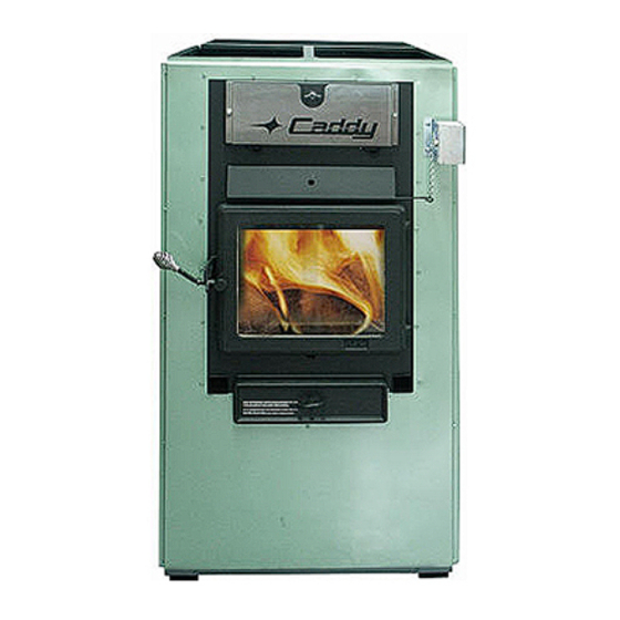
CADDY FURNACE- PF01010
FURNACE MODELS INCLUDED IN THIS MANUAL:
WOOD
ADD-ON
Read these instructions carefully before installing
Please keep this document!
Verified and tested for Canada
and the United States by :
Printed in Canada
instructions for the
WOOD
WOOD/ÉLECTRIC
ONLY
and operating your furnace.
250, de Copenhague,
St-Augustin-de-Desmaures (Quebec)
CANADA G3A 2H3
COMBINATION:
(15 KW
18 KW
20 KW)
This manual is available for free download on the
manufacturer's web site. It is a copyrighted document. Re‐sale
is strictly prohibited. The manufacturer may update this
manual from time to time and cannot be responsible for
problems, injuries, or damages arising out of the use of
information contained in any manual obtained from
.
unauthorized sources
PSG
COMBINATION
WOOD/OIL
45535A
11-11-2011
Advertisement
Table of Contents

Related Manuals for PSG Caddy PF01010


Summary of Contents for PSG Caddy PF01010
- Page 1 250, de Copenhague, St-Augustin-de-Desmaures (Quebec) CANADA G3A 2H3 Installation and operating instructions for the CADDY FURNACE- PF01010 FURNACE MODELS INCLUDED IN THIS MANUAL: COMBINATION: COMBINATION WOOD WOOD WOOD/ÉLECTRIC WOOD/OIL ADD-ON ONLY (15 KW 18 KW 20 KW) Read these instructions carefully before installing and operating your furnace.
- Page 2 As one of the largest and most respected wood furnace manufacturer in North America, PSG prides itself in the quality and performance of all its products. This manual is intended to help you in getting the most satisfaction out of the use of this product.
-
Page 3: Table Of Contents
Table des matières INTRODUCTION ......................7 CHIMNEY AND DRAFT ....................8 PART A - SAFETY RULES ..................... 9 GENERAL REQUIREMENTS ..................9 ODOUR FROM THE PAINT .................... 9 ASH DISPOSAL ....................... 9 CREOSOTE BUILD-UP AND REMOVAL ................ 9 SMOKE DETECTOR ..................... 10 DOOR GLASS ........................ - Page 4 3.1.6.5 WIRING DIAGRAM FOR CONNECTION OF THE CADDY ADD-ON WITH AN EXISTING GAS OR ELECTRIC FURNACE ..............35 3.1.7 OPERATING INSTRUCTIONS ................36 3.1.8 TECHNICAL DATA CADDY ADD-ON ..............37 CADDY WOOD ONLY FURNACE ................. 39 3.2.1 NECESSARY COMPONENTS FOR CADDY WOOD ONLY FURNACE ....39 3.2.2 APPLIANCE INSTALLATION .................
- Page 5 3.3.6 TECHNICAL DATA ....................63 CADDY WOOD/OIL COMBINATION FURNACE ............65 3.4.1 NECESSARY COMPONENTS FOR CADDY WOOD/OIL COMBINATION FURNACE ......................65 3.4.2 INTRODUCTION ....................65 3.4.3 GENERAL INFORMATION FOR OIL FURNACE ..........65 3.4.3.1 DRAFT AND CHIMNEY ....................66 3.4.3.2 OIL TANK AND PIPING ....................
- Page 6 PART C – OPERATION ....................81 LIGHTING OF THE WOOD FURNACE ................. 81 PREHEATING ........................ 81 HEATING ........................82 FIRST SIGNS OF AN OVERHEATING FURNACE ARE: ..........82 WOOD AS A COMBUSTIBLE ..................82 CHIMNEY FIRE......................83 LOCAL FIRE DEPARTMENT ..................84 PROLONGED POWER OUTAGE .................
-
Page 7: Introduction
1.1 INTRODUCTION Take note that this furnace uses the same wood burning technology as a high efficiency EPA certified wood burning stove. This applies to the lighting, the ember bed, and the minimum combustion air intake which was calibrated to burn good seasoned cordwood. -
Page 8: Chimney And Draft
1.2 CHIMNEY AND DRAFT This furnace must be connected to a chimney certified for wood burning heating appliances; a 6” connector and chimney is mandatory. When connected to an oil heating system, the smoke pipe must have a 5” diameter. If the chimney draft exceeds -0.06’’... -
Page 9: Part A - Safety Rules
2 PART A - SAFETY RULES 2.1 GENERAL REQUIREMENTS Make sure the chimney outlet and the pipes are clean and in good condition. DO NOT USE CHEMICAL PRODUCTS OR LIQUIDS TO LIGHT THE FIRE. DO NOT BURN WASTES OR FLAMMABLE LIQUIDS SUCH AS GASOLINE, NAPHTHA, MOTOR OIL, OR OTHER UNSUITABLE MATTERS. -
Page 10: Smoke Detector
When ignited, creosote produces an extremely hot fire inside the chimney. To avoid this situation, it is important to do the rotation of wood away from heating appliances and lighting products. Inspect the chimney system at regular intervals to determine a cleaning cycle. A weekly cleaning might be required during mild temperature periods but a monthly cleaning should be sufficient during cold periods. -
Page 11: Glass Characteristics
The glass is made of 3/16” (5 mm) thick ceramic glass. Do not operate your wood furnace with a broken glass, as this could seriously damage your furnace. You can purchase a replacement glass from your PSG dealer. 2.8 ASH DRAWER Your furnace is equipped with an ash drawer to collect ashes produced by the combustion of wood. -
Page 12: Damper
CAUSES RESTRICTION PROPER INSTALLATION IMPROPER INSTALLATION 2- A minimum rise of ¼” per horizontal foot must be respected. 2.11 DAMPER The barometric damper must be adjusted so that the maximum draft measured at the furnace outlet is limited to -0.06 in. w.c. However, the minimum draft to be respected at all times is -0.04 in. -
Page 13: Fresh Air Intake
2.12 FRESH AIR INTAKE When the furnace and the chimney are completely cold, it may be necessary to provide fresh air by opening a door or a window for a few minutes while lighting the fire. Take note that a house constructed or renovated in order to be airtight may lack the volume of fresh air necessary for the proper combustion of a solid-fuel heating appliance. -
Page 14: Filters
INSULATED PIPE AIR SUPPLY AIR INLET EXTERIOR WALL 2.13 FILTERS WARNING THE FURNACE SHOULD NEVER BE OPERATED WITHOUT FILTERS. THIS APPLIES ESPECIALLY TEMPORARY HEATING DURING CONSTRUCTION PERIOD. OPERATING THE FURNACE WITHOUT FILTERS WOULD ALLOW DUST AND OTHER PARTICLES IN THE AIR TO CIRCULATE FREELY AND TO PENETRATE INTO THE FAN AND MOTOR CARTERS, CAUSING SOME DEFECTS. -
Page 15: Part B - Installation
3 PART B - INSTALLATION WARNING RESPECT THE LOCAL CODES (WHEN IN DOUBT, CONSULT YOUR LOCAL DEALER). Before installation, please read the instructions carefully and make sure you understand them: Installation must be made in accordance with the CSA B.365 « Installation code for solid-fuel-burning appliances and equipment »... - Page 16 Installation Instructions CADDY WOOD ADD-ON PF01010 + PA08522...
-
Page 17: Caddy Wood Add-On
3.1 CADDY WOOD ADD-ON 3.1.1 NECESSARY COMPONENTS FOR CADDY WOOD ADD-ON The fan limit control assembly PA08522 is necessary for the Caddy wood Add- on, but it is not provided with the furnace and has to be purchased separately. 3.1.2 SAFETY PRECAUTION CAUTION THE OPERATION OF A GAS FURNACE MUST BE VERIFIED FOR... -
Page 18: Appliance Installation
WARNING THE ELECTRICAL CURRENT FLOWING THROUGH THE BLOWER MOTOR SHALL NOT EXCEED THE NAMEPLATE RATING. 3.1.5 APPLIANCE INSTALLATION If the exiting furnace must be modified, the following standards mist be respected: Wood-oil NFPA 31: Standard for the installation of oil-burning equipment. ... -
Page 19: Matching The Transfer Duct Between The Two Heat Generators
3.1.5.2 MATCHING THE TRANSFER DUCT BETWEEN THE TWO HEAT GENERATORS Install the plenum and heating ducts in line as in OPTION 1 and 2 of this section. Configurations shown in Examples 1, 2 and 3 of this same section are prohibited. - Page 20 3. Make the following verifications: a) Oil furnace: CFM = orifice size (SI)(liter/hour) x 39 023 x E 1.21 x t CFM = orifice size (Imperial)(gallon/hour) x 140 000 x E 1.1 x t E : Average heat generator efficiency (0.75) t: Temperature rise (ºC) b) Electric furnace: ...
- Page 21 Option 1 Option 2 *Minimum duct size 260 square inches * R = Minimum radius 6 inches...
- Page 22 Example 1 Example 2...
-
Page 23: Minimum Clearances To Combustible Materials For Caddy Wood Add-On
Example 3 3.1.5.3 MINIMUM CLEARANCES TO COMBUSTIBLE MATERIALS FOR CADDY WOOD ADD-ON N.B.: THIS APPLIANCE MUST BE INSTALLED IN ACCORDANCE WITH THE INSTRUCTIONS ON THE CERTIFICATION PLATE APPLIED ON THE UNIT. The floor on which the furnace is installed may be combustible. On a combustible floor, use a protective plate exceeding 8 inches on each side of the unit, 16 inches from the front of the door in the United States and 18 inches from the front of the door in Canada is required. - Page 24 Figure 3.1.4.3 a...
-
Page 25: Installing The Connecting Duct From The Existing Furnace
N.B.: TO ENSURE ADEQUATE STATIC PRESSURE, THE SYSTEM SHOULD BE BUILT IN A WAY THAT THE VOLUME OF COLD AIR RETURN IS AT LEAST EQUAL OR SLIGHTLY HIGHER THAN THE VOLUME OF THE HOT AIR DISTRIBUTION. Figure 3.1.4.3 b - Hot air plenum minimal height. The hot air plenum coming out of the furnace is to have a minimum height of 24"... - Page 26 Remove the screws (D) securing the large panel on the right side of the furnace (C) and secure it to the left side. Secure the panel that was on the left side of the furnace (E) to the right side with the screws kept (D).
- Page 27 To install the connecting duct from the existing furnace on the right side of your CADDY Add-on furnace, unscrew the screws (A) securing the smallest panel (B) on right side of the furnace (you can dispose of the panel). Connect the duct.
-
Page 28: Pipe Connector And Damper
3.1.5.5 PIPE CONNECTOR AND DAMPER The Caddy wood Add-on furnace must be connected to a duct system and a chimney that are in good condition; even if it is allowed, the use of separate chimneys is recommended. If the furnace is connected to an oil furnace and both appliances must share the same chimney, the chimney and smoke connector must be 7”... -
Page 29: Installation Of The Fan Limit Control And Wiring With An Existing Oil Furnace
3.1.6.1 INSTALLATION OF THE FAN LIMIT CONTROL AND WIRING WITH AN EXISTING OIL FURNACE Note: the fan limit control PA08522 (G) is not provided with the furnace and has to be purchased separately. To install the fan limit control assembly PA08522, (not included with the furnace), remove the cover on the fan limit control (G) and the cover on the junction box (D). - Page 31 Run a cable (F) from your house electrical entrance to the fan limit control’s junction box. Note: It is recommended to connect the Caddy Add-on on the same circuit as the existing furnace. Pull the red and black wires (E) out of the junction box through the wire grommet.
- Page 32 Run an 18-2 cable from the thermostat (A) of the Add-on to the fan limit assembly’s junction box (D). Run an 18-2 cable from the thermostat (B) of the existing oil furnace to the fan limit assembly’s junction box (D). ...
-
Page 33: Servomotor Installation
3.1.6.2 SERVOMOTOR INSTALLATION Install the servomotor on the right side of the front of the furnace; above the door (use the pre-drilled holes). The chain that links the air inlet damper to the motor must have a play of 1/8". When there is no call for heat, the air inlet damper must be completely closed and the chain must be hooked to the servomotor at the “8 o’clock”... -
Page 34: Wiring Diagram For Connection Of The Caddy Add-On With An Existing Oil Furnace
3.1.6.4 WIRING DIAGRAM FOR CONNECTION OF THE CADDY ADD-ON WITH AN EXISTING OIL FURNACE... -
Page 35: Wiring Diagram For Connection Of The Caddy Add-On With An Existing Gas Or Electric Furnace
3.1.6.5 WIRING DIAGRAM FOR CONNECTION OF THE CADDY ADD-ON WITH AN EXISTING GAS OR ELECTRIC FURNACE... -
Page 36: Operating Instructions
3.1.7 OPERATING INSTRUCTIONS Operate the existing furnace periodically to ensure that it will operate satisfactorily when needed. On the wood furnace, the thermostat controls the air inlet damper. When the thermostat calls for heat, the damper opens and the combustion is stirred up. When the furnace gets hot enough, the fan limit control activates the blower motor at the speed selected for wood heating. -
Page 37: Technical Data Caddy Add-On
3.1.8 TECHNICAL DATA CADDY ADD-ON ADD-ON ADD-ON 29 7/8" 43 1/2" 26" 22" 47 7/8" 14 1/2" 28 9/16" FLUE 6" 24 9/16" WEIGHT 510 Lb GÉNÉRAL TECHNICAL DATA MODELE TEMP. BTU/HR STATIC PRESSURE VARIABLE (WOOD) MIN. MAX. (°F) CADDY 140 000 ADD-ON... - Page 38 Installation instructions for CADDY WOOD ONLY FURNACE PF01010 + PA08568 + PA00500...
-
Page 39: Caddy Wood Only Furnace
3.2 CADDY WOOD ONLY FURNACE 3.2.1 NECESSARY COMPONENTS FOR CADDY WOOD ONLY FURNACE To use the configuration of the Caddy wood only furnace you have to assemble the blower assembly and fan limit control (PA08568), sold separately. The assembly instructions are in the instruction manual supplied with the blower assembly kit. -
Page 41: Minimum Clearances To Combustible Materials
3.2.2.3 MINIMUM CLEARANCES TO COMBUSTIBLE MATERIALS N.B.: THIS APPLIANCE MUST BE INSTALLED IN ACCORDANCE WITH THE INSTRUCTIONS ON THE CERTIFICATION PLATE APPLIED ON THE UNIT. The floor on which the furnace is installed may be combustible. On a combustible floor, use a protective plate exceeding 8 inches on each side of the unit, 16 inches from the front of the door in the United States and 18 inches from the front of the door in Canada is required. - Page 42 Figure 3.2.2.3 a...
-
Page 43: Connecting Pipe And Manual Damper
N.B.: TO ENSURE ADEQUATE STATIC PRESSURE, THE SYSTEM SHOULD BE BUILT IN A WAY THAT THE VOLUME OF COLD AIR RETURN IS AT LEAST EQUAL OR SLIGHTLY HIGHER THAN THE VOLUME OF THE HOT AIR DISTRIBUTION. Figure 3.2.2.3 b - Hot air plenum minimal height. The hot air plenum coming out of the furnace is to have a minimum height of 24"... -
Page 44: Electrical Connections
3.2.3 ELECTRICAL CONNECTIONS The following instructions do not replace those of the local code. Installation and verification of this appliance must be done by a qualified service man. All wiring from the service panel to the heating unit must comply with the electrical code in force and all local regulations. -
Page 45: Thermostat Installation
SERVOMOTOR Plastic grummets are installed on the upper edge of the blower box through which the blower cable (prewired 14-3 BX) will run before reaching the junction box located next to the blower where it will be connected. The low voltage control circuit will be fed from the transformer attached to the junction box of the fan limit assembly and the 120 volts circuit from the house electrical entrance will also be connected to that junction box as per the wiring diagram... -
Page 46: Wiring Diagram
3.2.3.4 WIRING DIAGRAM Make the connection from the blower to the fan limit control. Connect the servomotor and the thermostat to the transformer supplied with the fan limit kit. Then feed the fan limit control with the current from the electrical panel of the house. -
Page 47: Operating Instructions
3.2.4 OPERATING INSTRUCTIONS 3.2.4.1 CONTROL SYSTEM On wood only furnaces, when the thermostat calls for heat, the air inlet damper opens and the fire stirs-up; when the temperature inside the furnace is sufficient, the fan limit control will turn the blower on at the speed selected for wood heating and this one will stay on until the temperature drops down to the fan OFF setting. -
Page 48: Technical Data Caddy
3.2.5 TECHNICAL DATA CADDY CADDY CADDY 48” 24 9/16” 26” 43 1/2” 47 13/16” * 6" FLUE 15 3/4” X 24 3/4” 590 lb WEIGHT 28 9/16” * If desired, to allow the retrofit to wood/oil configuration, we suggest the use of a 7”... - Page 49 Installation instructions for CADDY WOOD/ELECTRIC COMBINATION FURNACE PF01010 + PA08568 + PA01000, PA01050 ou PA01100...
-
Page 50: Caddy Wood/Electric Combination Furnace
3.3 CADDY WOOD/ELECTRIC COMBINATION FURNACE 3.3.1 NECESSARY COMPONENTS FOR CADDY WOOD/ELECTRIC COMBINATION FURNACE To use the configuration of the Caddy wood/electric furnace you have to assemble the blower assembly (PA08568), sold separately. The assembly instructions are in the instruction manual (Step 1 to 5) supplied with the blower assembly kit. -
Page 51: Parallel Installation
3.3.3.2 PARALLEL INSTALLATION See Section 3.2.2.2, in Caddy wood only furnace. 3.3.3.3 MINIMUM CLEARANCES TO COMBUSTIBLE MATERIALS N.B.: THIS APPLIANCE MUST BE INSTALLED IN ACCORDANCE WITH THE INSTRUCTIONS ON THE CERTIFICATION PLATE APPLIED ON THE UNIT. The floor on which the furnace is installed may be combustible. On a combustible floor, use a protective plate exceeding 8 inches on each side of the unit, 16 inches from the front of the door in the United States and 18 inches from the front of the door in Canada is required. - Page 52 Figure 3.3.3.3 a...
-
Page 53: Connecting Pipe And Manual Damper
N.B.: TO ENSURE ADEQUATE STATIC PRESSURE, THE SYSTEM SHOULD BE BUILT IN A WAY THAT THE VOLUME OF COLD AIR RETURN IS AT LEAST EQUAL OR SLIGHTLY HIGHER THAN THE VOLUME OF THE HOT AIR DISTRIBUTION. Figure 3.3.3.3 b - Hot air plenum minimal height. The hot air plenum coming out of the furnace is to have a minimum height of 24"... -
Page 54: Electric Unit
3.3.4.3 ELECTRIC UNIT The wood/electric combination model uses two wall thermostats; one controls the electric heat and the other one the wood heat. In this configuration, the electric heat has priority over the wood. Whenever there is a call for heat from the electric thermostat, the air intake damper closes, the blower kicks on and the electric elements turn on in sequence of 4 to 5 kW at a time. - Page 55 OUTSIDE VIEW OF THE ELECTRIC UNIT...
-
Page 56: Optional Electric Element And Fan Limit Control Installation
3.3.4.4 OPTIONAL ELECTRIC ELEMENT AND FAN LIMIT CONTROL INSTALLATION Your Caddy furnace can be installed with an optional electric element (15, 18 or 20 kW). The installation must be performed by a qualified professional. Remove the screws (A) securing the electric unit access panel (B) to the left side of the furnace. - Page 57 Once the wiring as per the wiring diagram in this section completed, slide the electric element assembly (E) into the left hand side opening in the furnace cabinet. To secure the electric element furnace, use four of the eight screws (A) kept in Step 1.
- Page 58 Remove the fan limit control’s cover (F). Secure the fan limit control bracket provided with your furnace, on the top edge of the left or right side of the unit (two holes on each side have already been drilled on the edges furnace).
- Page 59 Using a flat screwdriver, remove the three knockouts located on the left electric element panel. Remove also the knockout on the right lower corner on the back of the furnace. Run the long “BX” cable from the fan limit control (2) through the middle opening made on the electric element panel.
- Page 60 Run an 18-2 cable (not supplied) from thermostat included with your furnace through the top opening made in Step 6. Run an 18-2 cable (not supplied) from thermostat included with your electric element through opening made in Step Run an 18-2 cable (not supplied) from...
- Page 61 Using flat screwdriver, remove the largest knockout located on the left access panel of the electric element. Run the feeder cable (not supplied) from house main entrance (6) through the opening made in left access panel. Note: Refer to electrical diagram included with the electrical element for wiring.
-
Page 62: Wiring Diagram
3.3.4.5 WIRING DIAGRAM Refer to electric diagram included with the electrical unit. -
Page 63: Technical Data - Electric Mode
3.3.4.6 TECHNICAL DATA – ELECTRIC MODE TEMP. TOTAL # OF OUTPUT ALIMENT. VOLTAGE MODEL VAR. BTU/H AMPERAGE BREAKER ÉLÉMENTS (CFM) CALIBRE 1 PHASE (OF) 15 KW 1300 51195 120/240 3 – 5 KW 2 – 5 KW, 2 – 18 KW 1300 61434 120/240... - Page 64 Installation instructions for CADDY WOOD/OIL COMBINATION FURNACE PF01010 + PA08568 + PA03050 ou PA03100...
-
Page 65: Caddy Wood/Oil Combination Furnace
3.4 CADDY WOOD/OIL COMBINATION FURNACE 3.4.1 NECESSARY COMPONENTS FOR CADDY WOOD/OIL COMBINATION FURNACE To use the configuration of the Caddy wood/oil furnace you have to assemble the blower assembly (PA08568), sold separately. The assembly instructions are in the instruction manual supplied with the blower assembly kit (follow steps 1 to 5). You must also assemble the oil assembly kit, the fan limit controls for wood and for oil as well as the burner. -
Page 66: Draft And Chimney
WARNING THE INSTALLATION OF THE WOOD/OIL COMBINATION FURNACE MUST BE DONE IN ACCORDANCE WITH THE RULES OF THE AUTHORITIES HAVING JURISDICTION AND THE CAN/CSA B-139 M-91 STANDARD FOR OIL BURNING HEATING APPLIANCES. WARNING OIL BURNING FURNACES ARE NOT APPROVED FOR USE WITH COMBUSTIBLE HEAVIER THAN NO.2 OIL (FURNACE OIL). -
Page 67: Burner Pump
3.4.3.3 BURNER PUMP When the tank is located below the unit, the basic single course pump, powered by a single duct, can compensate for a drop of 8 feet (244 cm) measured between tank outlet and the height of entry into the burner. When the rise is more than 8 feet (244 cm) and not exceeding 10 feet (305 cm), a by-pass plug (provided with the burner) must be inserted in the pump and an oil return pipe must be installed. - Page 68 Figure 3.4.4.3 a...
-
Page 69: Connecting Pipe And Manual Damper
N.B.: TO ENSURE ADEQUATE STATIC PRESSURE, THE SYSTEM SHOULD BE BUILT IN A WAY THAT THE VOLUME OF COLD AIR RETURN IS AT LEAST EQUAL OR SLIGHTLY HIGHER THAN THE VOLUME OF THE HOT AIR DISTRIBUTION. Figure 3.4.4.3 b - Hot air plenum minimal height. The hot air plenum coming out of the furnace is to have a minimum height of 24"... -
Page 71: Electrical Connections
3.4.5 ELECTRICAL CONNECTIONS The following instructions do not replace those of the local code. Installation and verification of this appliance must be done by a qualified service man. All wiring from the service panel to the heating unit must comply with the electrical code in force and all local regulations. -
Page 72: Wiring Diagram
3.4.5.4 WIRING DIAGRAM (The location of the fan limit control for wood is in the plenum and the fan limit control for oil is located on the panel on the exhaust pipe side). Wiring diagram for Beckett Burner... - Page 73 Wiring diagram for Riello Burner...
-
Page 74: Operating Instructions
3.4.6 OPERATING INSTRUCTIONS 3.4.6.1 FAN LIMIT CONTROL The fan limit control settings may need to be adjusted depending on the installation, but they are set at 100 °F (Fan OFF) and 250 °F (Fan ON) at the factory and these settings will work best in most installations. It is preferable that the setting "Fan OFF"... -
Page 75: Temporary Disengagement Of The Burner
A green diagnostic light on the control has four states: On = Flame present Off = No flame 2 seconds On, 2 seconds Off = "Recycle" mode 1/2 second On, 1/2 second Off = "Lockout" mode TEMPORARY SHUT- 3.4.6.5 TEMPORARY DISENGAGEMENT OF THE BURNER By pressing and holding the reset button, the burner will shut-off until the reset button is released. -
Page 76: Combustion Verification Procedure
3.4.6.7 COMBUSTION VERIFICATION PROCEDURE: A. DRILL 9/32" DIAMETER HOLE EVACUATION PIPE APPROXIMATELY 18" FROM THE OUTLET. B. CLOSE THE DOOR AND THE AIR INTAKE OF THE WOOD BURNING FURNACE. C. LIGHT THE BURNER FOR AT LEAST 10 TO 15 MINUTES. D. -
Page 77: Electrodes Setting
3.4.6.8 ELECTRODES SETTING The electrodes must be adjusted by a qualified technician. A proper positioning of the electrodes is important to get an efficient lighting of the oil and and efficient dispersion of the oil jet 3.4.6.9 ELECTRODE SETTING FOR "F" HEAD 5/32"... -
Page 78: Appliance Start-Up
WARNING 1. REFER TO THE RATING PLATE FOR THE PUMP PRESSURE AND THE NOZZLE TYPE. 2. REFER TO THE OIL BURNER’S INSTRUCTIONS MANUAL FOR DETAILS ON THE PUMP. 3. FOR ELECTRODES SETTING, SEE THE OIL BURNER’S MANUAL. 4. FOR THE START-UP AND ADJUSTMENT OF THE BURNER, SEE OIL BURNER’S INSTRUCTION MANUAL. -
Page 79: Oil Unit Maintenance
3.4.7 OIL UNIT MAINTENANCE At the beginning of heating season, have the complete installation inspected by a qualified service man, especially the lighting system and the controls. NOTE: THE UNIT’S MAINTENANCE, REPAIRS AND THE CLEANING OF THE OIL FILTER MUST BE DONE BY A QUALIFIED TECHNICIAN. Before calling for service, first check the following: ... -
Page 80: Caddy Technical Data
3.4.8 CADDY TECHNICAL DATA CADDY WOOD/OIL CADDY WOOD/OIL 48” 43 1/2” 26” ** 34 3/16” 47 13/16” 56 1/16” 15 3/4” X 24 3/4” 33 13/16” 28 9/16” * 7" FLUE 24 9/16” ** 590 lb WEIGHT * A 6” to 7” reducer must be installed at the flue outlet of the furnace. ** Does not include the oil burner (sold separately). -
Page 81: Part C - Operation
4 PART C – OPERATION 4.1 LIGHTING OF THE WOOD FURNACE WARNING NEVER USE CHEMICALS OR FLAMMABLE LIQUIDS TO LIGHT THE FIRE 1. Open the door. Note: if there already is a bed of embers in the combustion chamber, proceed directly to the PREHEATING step. -
Page 82: Heating
4.3 HEATING 1. Poke the fire and spread the embers evenly at the center of the combustion chamber before adding more wood. 2. Avoid overfilling the combustion chamber; air must be allowed to circulate freely through the upper portion of the chamber for the stove to perform best. Also remember that a small hot fire burns cleaner than a big smoldering one. -
Page 83: Chimney Fire
combustion. It is strongly recommended to let your wood dry in a place where it is exposed to sun and open air but protected from precipitations. DO NOT BURN COAL IN THIS FURNACE. If you notice a significant quantity of smoke in the house: 1. -
Page 84: Local Fire Department
4.7 LOCAL FIRE DEPARTMENT Telephone: ___________________________________ 4.8 PROLONGED POWER OUTAGE To reduce the risk of overheating during a prolonged power outage (more than 10 minutes), it is recommended to make certain that the air intake damper is closed. Open the blower access panel and remove the air filter to improve the circulation of air around the combustion chamber of the Caddy furnace. -
Page 85: Part D - Maintenance
5 PART D - MAINTENANCE 5.1 HEAT EXCHANGERS CARE Heat exchangers must be cleaned thoroughly at the end of every heating season. During summer, the air in basements is damper and with minimal air circulation within the furnace, it can mix with creosote and/or sooth deposits in the exchangers to form an acid that could accelerate the corrosion process and induce premature decay of the steel. - Page 86 Cut view of the Caddy wood only furnace...
-
Page 87: Chimney Maintenance
5.2 CHIMNEY MAINTENANCE The most efficient way to sweep a chimney is to run a hard chimney sweeping brush. Brush from the top down so sooth and creosote deposits will detach from the chimney liner and fall down to the bottom of the chimney where it can be easily removed. -
Page 88: Door Gasket Relacement
5.6 DOOR GASKET RELACEMENT It is important to keep the door gasket in good condition. The door is adjusted at the factory to seal the door tight. After a while, the gasket could sink and the door must then be adjusted as described below. If the door still leaks after the maximum adjustment, replace the gasket (see Section 6.2, THE DOOR GASKET.) Door adjustment procedure:... -
Page 89: Part E - Remplacement Parts
Any required repair should be made without delay using genuine PSG parts. An exploded view and complete parts list is available for you on the PSG web site at www.psg-distribution.com. -
Page 90: Caddy Brick Layout
6.3 CADDY BRICK LAYOUT WARNING INSTALL CERAMIC INSULATION PANELS BEFORE LAYING THE BRICKS INSIDE COMBUSTION CHAMBER. - Page 91 BRICK LAYOUT ASH GRATE BRICK 4" X 8" (HD) BRICK 4" X 9" (HD) BRICK 4" X 8" (HD) SPECIAL BRICK 4 1/2" X 9" (HD) BRICK 1 1/4" X 9" (HD) BRICK 4 1/2" X 9" (HD) 1/2" BRICK 4 1/2" X 9" (HD)
-
Page 92: Part F - Ducts And Dampers Dimensions
7 PART F - DUCTS AND DAMPERS DIMENSIONS 7.1 DUCTS AND DAMPERS DIMENSIONS (EXAMPLES OF CALCULATION) SIMPLIFIED METHOD WARM AIR SYSTEM INSTALLATION DISTRIBUTION SYSTEM HOUSE DIMENSIONS Example: 28 x 40 bungalow = 1,120 sq. ft. Ducts size (heat) 4 inch outlet reduce by 1”... -
Page 93: Part G - Troubleshooting
8 PART G - TROUBLESHOOTING PROBLEM CAUSES SOLUTIONS Heating inefficient during the first Improper adjustment of the Adjust the damper, minimize the combustions. Lack of draft. barometric damper (opened too smoke pipe length and use 45 wide). Chimney flue restriction elbows. -
Page 94: Part H - Specifications
9 PART H - SPECIFICATIONS Caddy wood only furnace Combustible Wood Maximum heat input 140,000 BTU (41 kW) Maximum heat output 106,400 BTU (31,2 kW) Average heat output 69,160 BTU (20,3 kW) Thermostatic control Maximum efficiency 76% (LHV) / 71% (HHV) Average emissions 6.6 grams/hr ou 0,229 g/MJ Loading capacity... - Page 95 Optional oil burner input capacity 91,000 BTU (27 kW) Burner orifice at input 0,65 gal/h* (2,46 l/h) Pump pressure at input 120 PSI Standard burner Beckett AFG Other burner model approved Riello, Aero Efficiency 82 % Burner location Right Recommended service clearance (burner) 24”...
-
Page 96: Limited Lifetime Warranty
Firebrick * Pictures required Shall your unit or a components be defective, contact immediately your PSG dealer. Prior to your call make sure you have the following information necessary to your warranty claim treatment: ...
Need help?
Do you have a question about the Caddy PF01010 and is the answer not in the manual?
Questions and answers