Advertisement
Quick Links
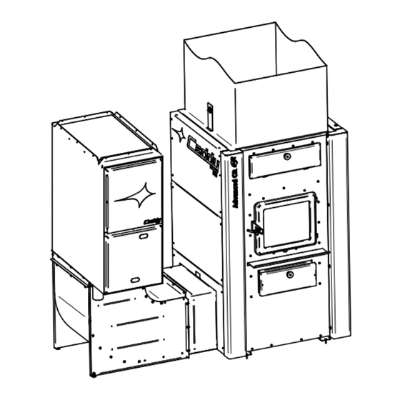
CONTROL UNIT AND OPTIONAL ADD-ON MODULES
WARNING: THE CADDY ADVANCED CR FURNACE MUST BE COUPLED WITH A GAS
FURNACE FROM A BRAND & MODEL RECOMMENDED BY PSG (SEE MANUAL)
WARNING: ELECTRICAL WIRING MUST BE DONE IN ACCORDANCE WITH LOCAL ELECTRIC
CODE BY A LICENSED PROFESSIONAL.
WARNING: IN A HEATPUMP/AC SETUP, WITH A COIL IN THE COLD AIR RETURN, IT IS
POSSIBLE THAT A CONDENSATION BUILDUP OCCURS IN THE COMBUSTION CHAMBER,
HEAT EXCHANCHER AND AROUND THE FURNACE. THE WARRANTY DOES NOT COVER
RUST IN THIS TYPE OF SETUP.
WARNING: IN A HEATPUMP/AC SETUP, NEVER PUT THE COIL IN WOOD BURNING PLENUM,
USE A BYPASS PLENUM. FAILURE TO DO SO WILL VOID THE WARRANTY.
Verified and tested for Canada and
the United States by an accredited
laboratory.
Eco-energy at the hearth
of your home
Printed in Canada
ASSEMBLY INSTRUCTIONS FOR
PA03060
CADDY ADVANCED CR FURNACE
This manual is available for free download on the
manufacturer's web site. It is a copyrighted document. Re-sale
is strictly prohibited. The manufacturer may update this manual
from time to time and cannot be responsible for problems,
injuries, or damages arising out of the use of information
contained in any manual obtained from unauthorized sources.
250, Copenhague street,
St-Augustin-de-Desmaures (Québec)
PSG
CANADA G3A 2H3
2024-07-16
46370A
Advertisement

Related Manuals for PSG Caddy PA03060


Summary of Contents for PSG Caddy PA03060
- Page 1 CADDY ADVANCED CR FURNACE WARNING: THE CADDY ADVANCED CR FURNACE MUST BE COUPLED WITH A GAS FURNACE FROM A BRAND & MODEL RECOMMENDED BY PSG (SEE MANUAL) WARNING: ELECTRICAL WIRING MUST BE DONE IN ACCORDANCE WITH LOCAL ELECTRIC CODE BY A LICENSED PROFESSIONAL.
- Page 2 Your Caddy Advanced CR furnace can be fitted with the add-on control unit kit. This option allows the installation of multiple accessories for unparalleled heating and comfort. This option allows you to connect: • A gas furnace (PSG-recommended model only) • A heat pump and its dampers • A humidifier •...
-
Page 3: Kit Content
2. Kit Content PL66310 – Jacket plug (1x) PL66370 – Lateral plug (1x) PL66355 – Wire chanel (1x) SE66322 – Link Card box (1x) PL66367 – Decorative panel (1x) 31389 – Wire clip (6x) 60462 – Ethernet cable (1x) 31048 – Metal screw (25x) 30163 –... - Page 4 3. Installation of the electronic link board For simplicity reasons, only the left side installation of the gas furnace is shown. Right side installation is also possible. Remove the desired side, bottom decorative panel, by removing its 4 plastic rivets. Use a flathead screwdriver to pry the rivet head away from the washer.
- Page 5 self-tapping screws 30163 to secure the link card box on the metal jacket. A rectangle marking (A) on the metal helps position the board housing. WARNING: For an installation on the left of the furnace, it is normal the link card box goes over the thermocouple access plate.
- Page 6 Connect transformer to the link board using the 2 wires with 1/4" connectors, 60024. Route wires 60024 as shown. See DETAIL views A & B for details. Remove the knock-out right next to the control card (A). Put a 7/8" grommet into the hole.
- Page 7 Run the ethernet cable 60462 between the furnace main circuit board and the link board. Run the cable as shown.
- Page 8 self-tapping screws 30163 to secure the wire channel PL66355 at the back so as to hide the wires. tab, illustrated below, inserted below the "bridge" of the wire channel (A). WARNING: IMPORTANT: DO NOT PINCH THE WIRES.
- Page 9 Here is the list of gas furnaces that can be installed in series with the Caddy Advanced CR furnace. PSG cannot be held responsible if the customer chooses another brand and model of furnace. The 3 Brands and their models are:...
- Page 10 Please refer to the gas furnace instructions in this regard. IMPORTANT: When installing with a gas furnace recommended by PSG, make sure the switches of the link board are in the "Gas" position. The position of the switches is represented by the small white filled square on the “Aux | Sw”...
- Page 11 SERIAL ADD-ON CONNECTION TO THE REAR OF THE CADDY ADVANCED CR WITH A GAS FURNACE In the case of a serial add-on connection with furnace at the rear of the Caddy Advanced CR, simply fit the ducts to the rear adapter.
- Page 12 SERIAL ADD-ON CONNECTION WITH A GAS FURNACE TO THE SIDE OF THE CADDY ADVANCED CR WARNING: INSTALLATION ON THE SIDE OF THE FURNACE IS DONNE WITH THE ANGLED SUPPORT PA08555, THE CONDUIT EXTENION PA08589 AND THE CORRESPONDING CONNEXION PLATE TO THE GAS FURNACE. Unscrew the furnace rear adapter.
- Page 13 Unscrew side panel on the bottom of the furnace. Set aside the metal screws. The panel can now be recycled. Take 15 metal screws 31048 and install the side panel adaptor to attach the serial add-on furnace duct PL66370.
- Page 14 INSTALLATION OF THE ANGLED SUPPORT PA08555, CONDUIT EXTENSION PA08589 AND CONNECTING PLATE FOR FURNACE (REFER TO THEIR RESPECTIVE MANUAL) The resulting assembly of the angled support PA08555 (A), conduit extension PA08589 (B) and the connexion plate (C) looks like the following image.
- Page 15 Connect the gas furnace harness 60473 on the link board box.
- Page 16 Pass harness through cable ties supplied in the manual kit. Screw on cable ties with self-tapping screws 30163. Hollows are made in the metal to position the fasteners (see image).
- Page 17 See the result after harness been properly passed. Connect wires from the harness 60473 into the gas furnace respecting color code following image. Do refer to the gas furnace instructions to pass the harness into the furnace. Wiring drawings are also present as reference at the end of this manual.
- Page 18 5. Thermostat Wiring 5.1 Wiring drawings for gas furnace Gas Furnace Thermostat Caddy CR Thermostat (wood)
- Page 19 Wiring with a heatpump and gas furnace Gas furnace and heatpump Caddy CR thermostat thermostat (wood)
- Page 20 6. Wiring of a Humidifier or Conduit Damper There are 3 block terminals on the link board box: 1. 24V block terminal: 24 Vac source 2. “HUM” block terminal: Connect the humidifier at this bloc terminal. When heat will be felt by the captors of the furnace the 24Vac signal will be present at the terminal.
-
Page 21: Decorative Panels
7. Decorative panels place bottom decorative panel PL66367, (coming from the PA03060 kit) with the plastic rivets 31366. Put back in place the middle and top decorative panels from the furnace (A). Use plastic rivets 31366 saved previously at step 3. - Page 22 Reinstall main board cover (A), fresh air intake cover (B) and finally the wiring cover (C) Be sure to cut the corner of the wire cover (D) (see DETAIL), to allow installation of the wiring channel.
- Page 23 8. Special features of installation with NAPOLEON furnaces On the Napoleon gas furnace control board, remove the “P5” jumper and set it over “NONE”. 9. Installation of electric element option PA01106 FOR FURTHER INFORMATION ON CONNECTING AND INSTALLING THE PA01106 ELECTRICAL ELEMENT, PLEASE REFER TO ITS INSTALLATION MANUAL.
- Page 24 Cooling Coil installation CAUTION: When installing a cooling or heat pump coil, ensure that the coil is isolated from the wood-burning plenum. Failure to do so may result in damage to your cooling coil. SBI declines all responsibility if this condition is not respected. IMPORTANT: Installing the A/C coil in the furnace cold air return or directly above the heat exchangers of the wood furnace (plenum) will create condensation inside the furnace and the heat exchangers and therefore create rust on the metal parts.
- Page 25 10.2 Refrigeration Coil installation in the cold air return in pair with an electrical element PA01106 WARNING: The max cooling power is 2.5 tons when the furnace is coupled with the PA08581(PSC) or PA08582(ECM) blowers. WARNING: The installation of the refrigeration coil in the cold air return could age prematurely the furnace. Traces of rust could appear.
- Page 26 10.3 Refrigeration Coil installation in the cold air return in pair with a gas furnace WARNING: The max cooling power is 2.5 tons when the furnace is coupled with a gas furnace. WARNING: The installation of the refrigeration coil in the cold air return could age prematurely the furnace. Traces of rust could appear.
-
Page 27: Blower Speed Adjustment
IMPORTANT: THIS SECTION ONLY APPLIES IF THE CADDY ADVANCED CR FURNACE IS INSTALLED WITH A CADDY BLOWER (PA08581 / PA08582) IN THE CASE OF A GAS FURNACE, RECOMMENDED BY PSG AND INSTALLED AS A SERIAL ADD-ON WITH THE CADDY ADVANCED CR, REFER TO THE GAS FURNACE MANUAL TO VARY THE SPEEDS. - Page 28 Wiring diagram for CADDY Advanced CR furnace with heat pump and PA01106 electric element kit For further information on wiring and installation of the PA01106 electrical element, please refer to the PA01106 manual. WARNING: If a wood-burning thermostat was previously connected to the furnace, disconnect it and connect it to the electronic link board.
- Page 29 Wiring diagram for CADDY Advanced CR with a gas furnace WARNING: IT IS MANDATORY TO CONNECT YLO AND Y (SOMETIMES CALLED Y1, Y2) EVEN IN THE CASE THE SYSTEM DOES NOT INCLUDE HEATPUMP/REFRIGERATION COIL. PSG WILL DECLINE RESPONSIBILITY IF THIS NOTE IS NOT RESPECTED.
- Page 30 Wiring diagram for CADDY Advanced CR furnace with gas furnace and heat pump WARNING: IT IS MANDATORY TO CONNECT YLO AND Y (SOMETIMES CALLED Y1, Y2) EVEN IN THE CASE THE SYSTEM DOES NOT INCLUDE HEATPUMP/REFRIGERATION COIL. PSG WILL DECLINE RESPONSIBILITY IF THIS NOTE IS NOT RESPECTED.
- Page 31 Reference for ventilation conduit without conduit accessories RÉFÉRENCE POUR INSTALLATION SANS SUPPORT COUDÉ PA08555 , EXTENSION DE CONDUIT PA08589 ET PLATEAU DE CONNEXION Build the metal ducts to connect to the furnace. CAUTION: The furnace must be able to be installed in a downflow position. IMPORTANT: The ductwork connected to the Caddy Advanced CR must be 19 3/8"...
- Page 32 This manual is available for free download on the manufacturer’s web site. It is a copyrighted document. Re- Verified and tested for Canada and sale is strictly prohibited. The manufacturer may update this the United States by an accredited manual from time to time and cannot be responsible for laboratory.
Need help?
Do you have a question about the Caddy PA03060 and is the answer not in the manual?
Questions and answers