Table of Contents
Advertisement
Installation and operating instructions
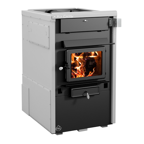
for the MAX CADDY WOOD FURNACE
FURNACE MODELS INCLUDED IN THIS MANUAL
WOOD ONLY
Read these instructions carefully before installing
You have purchased one of the finest wood or combination furnaces available
on the market. We are confident that your furnace will provide years of comfort
Verified and tested for Canada and
the United States by an accredited
laboratory.
Eco-energy at the hearth
of your home
Printed in Canada
(PF01102 model)
Certified according to CSA B415.1-10, CSA B366.1, UL391,
CSA C22.2 NO.236, UL 1995, CAN/CSA B140.4 and UL 727
and operating your furnace.
CONGRATULATIONS!
and safe operation.
Please keep this document!
COMBINATION
20 kW / 25 kW AND OIL
This manual is available for free download on the manufacturer's
web site. It is a copyrighted document. Re-sale is strictly
prohibited. The manufacturer may update this manual from time
to time and cannot be responsible for problems, injuries, or
damages arising out of the use of information contained in any
manual obtained from unauthorized sources.
St-Augustin-de-Desmaures (Quebec)
PSG
250, de Copenhague,
CANADA G3A 2H3
22-04-2016
45833A
Advertisement
Table of Contents

Related Manuals for PSG MAX CADDY PF01102


Summary of Contents for PSG MAX CADDY PF01102
-
Page 1: Wood Only
Installation and operating instructions for the MAX CADDY WOOD FURNACE (PF01102 model) Certified according to CSA B415.1-10, CSA B366.1, UL391, CSA C22.2 NO.236, UL 1995, CAN/CSA B140.4 and UL 727 FURNACE MODELS INCLUDED IN THIS MANUAL COMBINATION WOOD ONLY 20 kW / 25 kW AND OIL Read these instructions carefully before installing and operating your furnace. -
Page 2: Table Of Contents
TABLE OF CONTENT INTRODUCTION ..................................5 APPLIANCE PERFORMANCE ..............................6 GENERAL FEATURES ................................7 SPECIFICATIONS ..................................8 MAX CADDY FURNACE TECHNICAL DATA ........................... 9 FURNACE DIMENSIONS ................................9 CHIMNEY AND DRAFT ................................11 SAFETY RULES ..................................11 8.1. GENERAL REQUIREMENTS ............................11 8.2. - Page 3 11.7.2. COOL M ..................................37 11.7.3. CIRC M ) ............................37 AIR CIRCULATION 11.8. WOOD HEATING ................................38 11.8.1. LIGHTING ..................................38 11.8.2. PREHEATING ................................. 38 11.8.3. HEATING ..................................38 11.8.4. EARLY SIGNS OF AN OVERFIRED FURNACE: ......................38 11.8.5. WOOD AS HEATING FUEL ............................. 39 11.8.6.
- Page 4 28.4. 24V ADDITIONNAL EQUIPMENT ............................64 28.5. AIR CONDITIONNING DAMPER.............................. 64 28.6. HUMIDIFIER ..................................... 64 28.7. HEAT PUMP ..................................... 65 EXPLODED VIEW AND PART LIST ............................65 PSG LIMITED LIFETIME WARRANTY (REGULAR) ......................... 78 PSG LIMITED LIFETIME WARRANTY (PRIVILEGE) ........................79...
-
Page 5: Introduction
IMPORTANT NOTE: THE INSTALLATION OF THIS CENTRAL HEATING SYSTEM MUST BE PERFORMED BY A QUALIFIED TECHNICIAN. PSG RESERVES ITSELF THE RIGHT TO VOID ITS WARRANTY OR DENY TECHNICAL ADVICE IF THE FURNACE HAS NOT BEEN SOLD OR INSTALLED BY A PROFESSIONAL. -
Page 6: Appliance Performance
2. APPLIANCE PERFORMANCE Fuel type Dry cordwood Recommended heating area 1,500 to 3,500 ft² (139 to 325 m²) Firebox volume 4.9 ft³ (0.139 m³) Maximum burn time 17 hours Maximum input capacity (dry cordwood) 421,000 BTU Overall heat output rate (min. to max.) 19,243 BTU/h to 67,069 BTU/h (5.6 kW to 19.6 kW) Nominal heat output at 15lb/ft³... -
Page 7: General Features
3. GENERAL FEATURES Maximum log length 25 in (635 mm) / north-south* Diameter of the flue collar 6 in (152 mm) 6 in (152 mm) if installed as wood only or combined wood- Recommended connector pipe diameter electric Mandatory connector pipe diameter 7 in (178 mm) if installed as combined wood-oil 6 in (152 mm) if installed as wood only or combined wood- Recommended chimney diameter... -
Page 8: Specifications
4. SPECIFICATIONS Color Grey Thermostatic control Door type Single, glass with cast iron frame Glass type Ceramic glass Air return plenum – dimensions (Depth or Height) 17 15/16 in Air return plenum – dimension (Width) 19 15/16 in Hot air plenum – dimensions (Depth or Height) 32 1/8 in Hot air plenum –... -
Page 9: Max Caddy Furnace Technical Data
5. MAX CADDY FURNACE TECHNICAL DATA THEORETICAL TEMP MODEL (DIRECT DRIVE) STATIC PRESSURE FILTER DEBIT VAR. VENT MOT. VIT. (CFM) (OF) MIN. MAX. INCH H2O MAX CADDY WITH BLOWER / MAX CADDY G-10 2,100 16" x 20" x 1" ADD-ON (PARALLEL) 6. -
Page 11: Chimney And Draft
7. CHIMNEY AND DRAFT This furnace must be connected to a chimney certified for use with wood burning heating appliances. A 7-inch chimney and connector must be installed for the Max Caddy if it is used as a wood-oil unit, a wood-electrical-oil unit or if an oil option may be installed in the future. -
Page 12: Smoke Detector
The glass is made of 3/16" (5mm) thick ceramic glass. Do not operate your wood furnace with a broken glass, as this could seriously damage your furnace. You can purchase a replacement glass from your PSG dealer. 8.7. ASH DRAWER Your furnace is equipped with an ash drawer to collect ashes produced by the combustion of wood. -
Page 13: Max Caddy Wood Only Furnace, Combined Wood / Electric Or Parallel Add-On Pf01102
INSTALLATION AND OPERATION INSTRUCTIONS FOR MAX CADDY WOOD ONLY FURNACE, COMBINED WOOD / ELECTRIC OR PARALLEL ADD-ON PF01102 MAX CADDY FURNACE – WOOD ONLY MAX CADDY FURNACE – COMBINED WOOD/ELECTRIC... -
Page 14: Installation Instructions
9. INSTALLATION INSTRUCTIONS Installation must be made in accordance with the CSA B.365 « Installation code for solid-fuel-burning appliances and equipment » standard in Canada and NFPA 90B « Standard for the installation of warm air heating and air conditioning system »... - Page 15 Remove the four screws on the furnace, located on the side of the desired installation. Align the holes of the board housing the holes on the side of the furnace. Use the screws removed in the previous step to secure the housing to the furnace.
- Page 16 Take the telecommunication wire and pull it through the grommet located on the side where the housing board is installed. Once the telecommunication wire is out on the desired side, run it along the back of the furnace and pass it through the grommet at the bottom of link board...
- Page 17 Your furnace should also be connected to a 115V power source. To do so, open the cover power board housing. Connect the power cord to the terminals (Neutral) (Ground) L (Line). Refer to wiring diagram for connecting components. When done, secure the wires with a BX connector (not included) and replace the blower box cover.
-
Page 18: Touchscreen Installation And Connection
9.3. TOUCHSCREEN INSTALLATION AND CONNECTION The touch screen is used to operate the system. It must be installed on the support provided at the back of the furnace, on the same side as the link board housing. Connect link board with the touch screen using the telecommunication wire provided with the user manual. Plug the telecommunication wire in connector labeled LCD and pull it out of the board housing through the top grommet. -
Page 19: Hot Air Plenum Temperature Probe Installation And Connection (Rtd)
9.4. HOT AIR PLENUM TEMPERATURE PROBE INSTALLATION AND CONNECTION (RTD) On the Max Caddy, a RTD has to be installed on the side of the furnace using the support provided with the unit. The RTD is a sensor that reads the temperature inside the hot air plenum. It is critical to the good operation of the furnace. Refer to electric diagram for connection details. -
Page 20: Servomotor Installation And Connection
9.5. SERVOMOTOR INSTALLATION AND CONNECTION Your Max Caddy furnace is equipped with a servomotor. To install it, simply screw it in place in the two pre-drilled holes in the front of the furnace using two screws as shown below. Once installed, install the chain linking the servomotor with the air inlet damper as shown above. The chain must have a set of 1/8". -
Page 21: Unit Location
Then, you must connect the servomotor and the link board. Take the wires out of the servomotor and enter the wires in the wire cover through the grommet. Pull them out through the grommet next to the link board housing. For connection, refer to wiring diagram. -
Page 22: Minimum Clearances To Combustible Materials
9.7.1. MINIMUM CLEARANCES TO COMBUSTIBLE MATERIALS MINIMUM CLEARANCES 24" (610 mm) 8" (204 mm) 18" (458 mm) 1.5" (38.1 mm) 6" (153 mm) 6" (153 mm) 1" (26 mm) 24" (610 mm) 72" (1 829 mm) 24" (610 mm) HEAT SHIELD... -
Page 23: Minimum Clearances To Combustibles Materials For Air Return Duct
9.7.2. MINIMUM CLEARANCES TO COMBUSTIBLES MATERIALS FOR AIR RETURN DUCT The return air duct should be at least equal in size to the return air plenum. The air return duct can be installed at zero clearance to combustibles. 9.7.3. MINIMUM CLEARANCES TO COMBUSTIBLES MATERIALS FOR HOT AIR PLENUM Plenums installed on the furnace must be made of metal in accordance with CSA B365 or NFPA 90B. -
Page 24: Flue And Barometric Draft Control Connection
9.8. FLUE AND BAROMETRIC DRAFT CONTROL CONNECTION Before connecting the stove pipe, make sure you have removed any accessory from the flue pipe such as the scraper, shovel, and the poker. The flue outlet on the Max Caddy furnace is 6" in diameter and the wood only or wood/electric models may be installed with a 6"... -
Page 25: Electrical Connections
9.9. ELECTRICAL CONNECTIONS The following instructions do not replace those of the local code. Installation and verification of this appliance must be done by a qualified service man. All wiring from the service panel to the heating unit must comply with the electrical code in force and all local regulations. -
Page 26: Hot Air Plenum
NOTE: It is recommended to install an outside air inlet with a diameter of at least 4" in the room where the heating appliance is installed (see drawing below). Insulated pipe It is preferable to choose a wall which is not (full length) exposed to dominant winds, depending on the conditions surrounding your house. - Page 27 Conditional to; The maximum input power of the existing gas, oil or electric furnace should be equal or lower than 120 000 Btu/h. The clearances required for wood furnace must be respected. The clearances between the hot air ducts and combustible materials must meet the highest values between the two furnaces.
- Page 28 To ensure a safe installation, the two furnaces must not, at any time, run simultaneously. To do so, the thermostat controlling the existing furnace must be connected to your Max Caddy link board. This way, when a heating signal is sent to the existing furnace, the Max Caddy receives the same signal.
-
Page 29: Electrical Element Installation (Optional)
9.14. ELECTRICAL ELEMENT INSTALLATION (OPTIONAL) 9.14.1. INTRODUCTION Two electrical elements are available for the Max Caddy: and 20Kw et 25kW. These options include all components necessary for the installation. Instructions for installing the electrical elements are provided with the electrical element. WARNING: USE WIRING SUITABLE FOR 75 °C (NOT INCLUDED). -
Page 30: Thermostat Installation
10. THERMOSTAT INSTALLATION 10.1. WOOD FURNACE ONLY The furnace must be connected to a thermostat. You can use the one provided with the unit or use one that is already installed in your home. The thermostat must be installed on an inside wall and located where it is not likely to be affected by the draft coming from an air outlet. -
Page 31: Installation Of An Air Conditioning Unit
10.2. INSTALLATION OF AN AIR CONDITIONING UNIT The Max Caddy furnace has been tested with an optional air conditioning unit. If this option is chosen, we recommend an installation as per the graphic provided below. Damper A/C coil Damper This installation will provide the most efficient and safe operation of the air conditioning unit using the distribution blower of the Max Caddy furnace during summer. -
Page 32: Installation Of A Domestic Water Pre-Heating System Or A Humidifier
10.4. INSTALLATION OF A DOMESTIC WATER PRE-HEATING SYSTEM OR A HUMIDIFIER A water heating loop option is also available to pre-heat domestic water using the energy produced by the Max Caddy wood furnace. This water loop kit will be inserted between the wood combustion chamber and the heat exchangers. When heating with wood, the heat from the furnace will pre-heat domestic water that will be stored in a feed tank before entering your existing water heater. -
Page 33: System Configuration
11.2. SYSTEM CONFIGURATION Once the installation is complete and before using the unit, the furnace should be configured to activate all applicable functions depending on options chosen. To do this, it is important to know which options are installed on your furnace. 11.3. -
Page 34: Language Selection And Temperature Unit
11.3.2. LANGUAGE SELECTION AND TEMPERATURE UNIT To choose the language and temperature unit, press the "Settings" button. In the "Main" menu, choose "SETUP" and then "GENERAL". Choose the preferred language and temperature unit. 11.4. ADDING AUXILIARY HEATING SOURCE AND SELECTION OF OPTIONS To add an auxiliary source of heating or to add options to your furnace, press the "Settings"... -
Page 35: Auxiliary Heat Source Prioritization
11.4.3. AUXILIARY HEAT SOURCE PRIORITIZATION If you have configured one or many auxiliary heating sources (electrical element, heat pump, oil), you must choose the priority order when there is a heating demand. If, for example, the wood no longer provides sufficient heat, the auxiliary heating selected in priority one will take over. -
Page 36: Distribution Blower Speed Configuration
11.5. DISTRIBUTION BLOWER SPEED CONFIGURATION It is possible to adjust the speed of the distribution blower for circulation mode, air conditioning and any other mode of auxiliary heaters. NOTE: When heating with wood, the fan distribution speeds are programmed in order to provide the best thermal exchange and cannot be changed. -
Page 37: Operating Instructions
It is important to respect the velocity in the main duct, the secondary ducts, as well as the velocity at the room outlets. The static pressure of your system must be adjusted to at least 0.2 IN.W.C. and must not exceed 0.5 IN.W.C. Finally, make sure that you never exceed the maximum blower current. -
Page 38: Wood Heating
11.8. WOOD HEATING 11.8.1. LIGHTING 1. Open the furnace door Note: If there is already a bed of coals in the firebox, go to pre-heating. 2. Place one or two dry kindlings at the front of the furnace. 3. Place newspaper strips on top of the kindlings. 4. -
Page 39: Wood As Heating Fuel
11.8.5. WOOD AS HEATING FUEL ATTENTION NE JAMAIS FAIRE BRÛLER DE DÉCHETS, DE LA GAZOLINE, DU NAPHTA, DE L’HUILE À MOTEUR OU TOUT AUTRE PRODUIT SEMBLABLE. We recommend that you burn dry hard wood only. There are two important factors to be considered when choosing a type of wood: the moisture content and the wood density. -
Page 40: Maintenance
12. MAINTENANCE 12.1. MAINTENANCE OF THE EXCHANGERS Heat exchangers must be cleaned thoroughly at the end of every heating season. During summer, the air in basements is damper and with minimal air circulation within the furnace, it can mix with creosote and/or sooth deposits in the exchangers to form an acid that could accelerate the corrosion process and induce premature decay of the steel. -
Page 41: Chimney Maintenance
12.2. CHIMNEY MAINTENANCE The most efficient way to sweep a chimney is to run a hard chimney sweeping brush. Brush from the top down so sooth and creosote deposits will detach from the chimney liner and fall down to the bottom of the chimney where it can be easily removed. -
Page 42: Replacement Parts
13. REPLACEMENT PARTS Your PSG furnace is designed to burn clean and requires little maintenance. It is recommended to conduct a visual inspection at least once a month to uncover any damage to the unit. Any defect must be repaired without delay using genuine PSG replacement parts. -
Page 43: Validating Status Of A Component
14.1. VALIDATING STATUS OF A COMPONENT When using your furnace, you can validate at any time, the status of any of the following components: Distribution blower Air damper Temperature probe (RTD) Hot water system Humidifier ... -
Page 44: Temperature Probe (Rtd)
14.1.3. TEMPERATURE PROBE (RTD) The temperature probe continuously reads the temperature in the plenum and displays it on the main page in the upper right corner. If the probe fails, the error message "PLENUM OVERTEMP" will appear. See section 14.2 - MAIN ERROR CODES, POSSIBLE CAUSES AND SOLUTIONS for more information. -
Page 45: No Heat
The temperature probe (RTD) is disconnected or defective If the displayed plenum temperature on the touch screen is F or 11 F, the temperature probe is either disconnected or defective. Check the probe connection (see Section 9.4 - HOT AIR PLENUM TEMPERATURE PROBE INSTALLATION AND CONNECTION (RTD) or replace if necessary. The air filter is dirty or clogged: Clean the furnace filter. -
Page 46: Smoke Smell
14.2.4. SMOKE SMELL Venting system leaks. Inspect all vent connections. All vent connector joints must be sealed and fastened in accordance with the vent manufacturer's instructions to ensure consistent performance and avoid smoke and ash spillage. Worn gaskets. Gaskets may be allowing smoke spillage (doors, clean out traps, etc). Make sure that all gaskets are in good condition and replace them with original parts if necessary. -
Page 47: General Electrical Diagram
15. GENERAL ELECTRICAL DIAGRAM... -
Page 48: Electrical Diagram For Parallel Furnace
16. ELECTRICAL DIAGRAM FOR PARALLEL FURNACE... -
Page 49: Electrical Diagram For Electric Unit
17. ELECTRICAL DIAGRAM FOR ELECTRIC UNIT... -
Page 50: Wood/Oil Combination Furnace
INSTALLATION AND OPERATION INSTRUCTIONS FOR WOOD/OIL COMBINATION FURNACE NECESSARY COMPONENTS FOR MAX CADDY WOOD/OIL COMBINATION FURNACE To use the configuration of the Max Caddy wood/oil furnace you have to assemble the blower assembly (PA08566), sold separately. The assembly instructions are in the instruction manual supplied with the blower assembly kit. You must also assemble the oil assembly kit. -
Page 51: General Information For Oil Furnace
GENERAL INFORMATION FOR OIL FURNACE READ THIS MANUAL THOROUGHLY BEFORE OPERATING THE FURNACE CAUTION CAUTION EXPLOSION OR FIRE HAZARD. FOR YOUR DO NOT ATTEMPT TO LIGHT THE BURNER SAFETY: DO NOT STORE OR USE WHEN EXCESS OIL HAS ACCUMULATED, GASOLINE OR ANY FLAMMABLE LIQUIDS WHEN THE APPLIANCE IS FULL OF OR VAPORS IN THE VICINITY OF THIS VAPOR, OR WHEN THE COMBUSTION... -
Page 52: General Notes
18. GENERAL NOTES This instructions manual treats mainly of the oil burning unit of your wood/oil combination furnace. To obtain the maximum efficiency out of your furnace, follow the advice below regarding the installation and operation of your WOOD/OIL combination furnace. ... -
Page 53: Appliance Installation
22. APPLIANCE INSTALLATION A Blocked Vent Switch is mandatory for installation with an oil fired appliance that normally operates with its vent system under a negative pressure. This device is intended to detect a blocked vent system, responds to hot flue gases backing up through its heat transfer tube, and can be wired to shut off the oil burner. -
Page 54: Floor Protection
MIMINUM CLEARANCES 24" (610 mm) 8" (203 mm) 18" (457 mm) 1.5" (mm) 6" (152 mm) 24" (610mm) 1" (25 mm) 24" (610mm) 72" (1829 mm) 9" (229mm) 24" (610 mm) HEAT SHIELD 22.4. FLOOR PROTECTION See Section 9.7.4 - FLOOR PROTECTION 22.5. -
Page 55: Different Installation
22.7. DIFFERENT INSTALLATION... -
Page 56: Combustion Air
22.8. COMBUSTION AIR See Section 9.11 - COMBUSTION AIR AND FRESH AIR INTAKE ADAPTER INSTALLATION (OPTIONAL) 22.9. ELECTRICAL WIRING See Section 9.9 - ELECTRICAL CONNECTIONS 22.10. THERMOSTAT See Section 10 - THERMOSTAT INSTALLATION 23. OPERATION INSTRUCTION 23.1. FAN SPEED CONTROL See Section 11.5 - DISTRIBUTION BLOWER SPEED CONFIGURATION 23.2. -
Page 57: Combustion Adjustment And Verification
23.6. COMBUSTION ADJUSTMENT AND VERIFICATION To enjoy the efficiency of our oil burning units, you must respect the following criterion: Oil burning units must be connected to flue pipes having at all times a sufficient draft to ensure an efficient and safe operation of unit. -
Page 58: Electrodes Setting
23.6.2. ELECTRODES SETTING The electrodes must be adjusted by a qualified technician. A proper positioning of the electrodes is important to get an efficient lighting of the oil. ELECTRODE SETTING FOR "F" HEAD 5/32" ELECTRODE 7/16" 1/16" NOZZLE WARNING: 1. REFER TO THE RATING PLATE FOR THE PUMP PRESSURE AND THE NOZZLE TYPE. 2. -
Page 59: Appliance Start-Up
23.7. APPLIANCE START-UP The start-up must be performed by a qualified technician. Make sure the installation is completed and the oil tank has been filled up. The oil line must also have been purged. CAUTION: CLOSE THE BLOWER COMPARTMENT ACCESS PANEL BEFORE STARTING THE BURNER. 23.8. -
Page 60: Service
25.2. SERVICE Before calling for service, first check the following Fuel supply Electric fuses or breakers Thermostat setting PC board settings The state of the green diagnostic LED on the burner control. Burner no.: _________________ Model: _______________ Date of installation: ___________________ Service telephone no.: Day: _________________________ Night: _____________________________ Dealer’s name and address ____________________________________________________________ TEST REPORT :... -
Page 61: Electrical Diagram Beckett Oil Unit
26. ELECTRICAL DIAGRAM BECKETT OIL UNIT... -
Page 62: Electrical Diagram Riello Oil Unit
27. ELECTRICAL DIAGRAM RIELLO OIL UNIT... -
Page 63: Link Board Options Connections
28. LINK BOARD OPTIONS CONNECTIONS 28.1. ELECTRICAL CONSUMPTION Your Max Caddy furnace is able to supply electrical 24V current to control various options. The options that can be supported are described in the table below. The maximum available 24V current is 1.66 amps (transformer 24V @ 40VA). -
Page 64: Additionnal Equipment
28.4. 24V ADDITIONNAL EQUIPMENT 28.5. AIR CONDITIONNING DAMPER 28.6. HUMIDIFIER... -
Page 65: Heat Pump
28.7. HEAT PUMP 29. EXPLODED VIEW AND PART LIST... - Page 73 IMPORTANT: THIS IS DATED INFORMATION. When requesting service or replacement parts for your stove, please provide the model number and the serial number. We reserve the right to change parts due to technology upgrade or availability. Contact an authorized dealer to obtain any of these parts. Never use substitute materials. Use of non- approved parts can result in poor performance and safety hazards.
- Page 74 Item Description 30124 SCREW #8 - 32 X 5/16'' TRUSS QUADREX ZINC SE56274 ASH DRAWER 21220 C-CAST BAFFLE 19 3/4" X 11 3/8" X 1 1/4" PL56764 REAR SECONDARY AIR TUBE PL56763 MIDDLE REAR SECONDARY AIR TUBE PL56761 MIDDLE FRONT SECONDARY AIR TUBE PL56760 FRONT SECONDARY AIR TUBE PL56356...
- Page 75 Item Description 21079 OIL UNIT COVER GASKET SE53269 OIL UNIT COVER ASSEMBLY WITH VISION TUBE 30210 WASHER 29/32" OD X 3/8" ID ZINC 30425 NUT BRASS 5/16 - 18 HEX 21085 BURNER / OIL UNIT GASKET 30423 3/8'' - 16 HEX ZINC NUT PL56465 RIGHT OIL UNIT PANEL 51024...
- Page 76 BLACK DRAWER HANDLE 3 25/32" PA08566 BLOWER ASSEMBLY PA08500 TOP AIR RETURN PLENUM KIT SE45833 MAX CADDY INSTRUCTION MANUAL KIT AC05961 PSG GREY 424C SPRAY PAINT AC05963 METALLIC BLACK STOVE PAINT - 85 g (3oz) AEROSOL PL48170 HEAT EXCHANGER SCRAPER PL48171 ASH SHOVEL PL48173...
- Page 77 Given the importance of the installation, PSG recommends that it is carried out by a professional certified in the Building Code so that the furnace delivers its full potential. This is why PSG offers an additional warranty that covers the cost of labor if your furnace has been purchased through an authorized PSG dealer.
-
Page 78: Psg Limited Lifetime Warranty (Regular)
Firebrick *Pictures required Shall your unit or a components be defective, contact immediately your PSG dealer. Prior to your call make sure you have the following information necessary to your warranty claim treatment: Your name, address and telephone number;... -
Page 79: Psg Limited Lifetime Warranty (Privilege)
1 year ceramic fibre blankets. Firebrick *Pictures required Shall your unit or a components be defective, contact immediately your PSG dealer. Prior to your call make sure you have the following information necessary to your warranty claim treatment: ...
Need help?
Do you have a question about the MAX CADDY PF01102 and is the answer not in the manual?
Questions and answers