Table of Contents
Advertisement
Quick Links
Installation and operating instructions
for the MAX CADDY wood furnace
CERTIFIED ACCORDING TO CSA B415.1-10, CAN/CSA B366.1 M91,UL391 4
NO.236-05, UL 1995 3
FURNACE MODELS INCLUDED IN THIS MANUAL
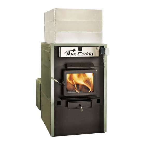
MAX CADDY WOOD AND COMBINATION FURNACE
Read these instructions carefully before installing
You have purchased one of the finest wood or combination furnaces
available on the market. We are confident that your furnace will provide
years of comfort and safe operation.
This manual is available for free download on the manufacturer's web site. It is a
copyrighted document. Re‐sale is strictly prohibited. The manufacturer may update this
manual from time to time and cannot be responsible for problems, injuries, or damages
arising out of the use of information contained in any manual obtained from
unauthorized sources.
Printed in Canada
READ THE MANUAL THOROUGHLY
BEFORE OPERATING THE FURNACE
RD
EDITION 2003, CSA B140.4-04 AND UL 727 9
20kW/25kW and UH-Max Caddy
and operating your furnace.
CONGRATULATIONS!
PSG
250 de Copenhague
Saint-Augustin-de-Desmaures
Quebec, Canada
G3A 2H3
TH
EDITION 2006, CAN/CSA C22.2
TH
EDITION 2006
Please keep this document!
45446A
17-10-2013
Advertisement
Table of Contents

Related Manuals for PSG MAX CADDY


Summary of Contents for PSG MAX CADDY
- Page 1 250 de Copenhague Saint-Augustin-de-Desmaures Quebec, Canada G3A 2H3 Installation and operating instructions for the MAX CADDY wood furnace READ THE MANUAL THOROUGHLY BEFORE OPERATING THE FURNACE CERTIFIED ACCORDING TO CSA B415.1-10, CAN/CSA B366.1 M91,UL391 4 EDITION 2006, CAN/CSA C22.2 NO.236-05, UL 1995 3 EDITION 2003, CSA B140.4-04 AND UL 727 9...
-
Page 2: Table Of Contents
INSTALLATION OF A DOMESTIC WATER PRE-HEATING SYSTEM (OPTIONAL) ..28 3.15 INSTALLATION OF AN AIR CONDITIONING UNIT ............. 29 3.16 OIL BURNER INSTALLATION – WOOD-OIL MAX CADDY (OPTIONAL) ......29 4. OPERATING INSTRUCTIONS ......................30 CONTROL SYSTEM ........................30 ... - Page 3 GENERAL ELECTRIC DIAGRAM WITH BECKETT OIL BURNER ........42 GENERAL ELECTRIC DIAGRAM WITH RIELLO OIL BURNER ........43 9. ELECTRIC DIAGRAM WITH OPTIONAL ELECTRICAL ELEMENT ........44 10. MAX CADDY TECHNICAL DATA ....................45 10.1 GENERAL TECHNICAL DATA ....................45 10.2 ...
- Page 4 IMPORTANT NOTE: THE INSTALLATION OF THIS CENTRAL HEATING SYSTEM MUST BE PERFORMED BY A QUALIFIED TECHNICIAN. PSG RESERVES ITSELF THE RIGHT TO VOID ITS WARRANTY OR DENY TECHNICAL ADVICE IF THE FURNACE HAS NOT BEEN SOLD OR INSTALLED BY A PROFESSIONAL.
-
Page 5: Wood Or Wood/Electric Combination Furnaces
This furnace must be connected to a chimney certified for use with wood burning heating appliances. A 7-inch chimney and connector are recommended for the Max Caddy if it is used as a wood-oil unit or a wood-oil-electric unit. If an oil option may be installed in the future, we also recommend a 7-inch chimney. If the furnace is to be used as a wood only unit, then a 6-inch chimney is recommended. -
Page 6: General Requirements
GENERAL REQUIREMENTS Make sure the chimney outlet and the pipes are clean and in good condition. DO NOT USE CHEMICAL PRODUCTS OR LIQUIDS TO LIGHT THE FIRE. Do not burn wood coated with paint, glue or chemical products. ... -
Page 7: Smoke Detector
The glass is made of 3/16” (5mm) thick Pyroceram. Do not operate your wood furnace with a broken glass, as this could seriously damage your furnace. You can purchase a replacement glass from your PSG dealer. ASH DRAWER Your furnace is equipped with an ash drawer to collect ashes produced by the combustion of wood. This drawer must not be left open during combustion as this may cause over firing and serious damages to the furnace. -
Page 8: Appliance Installation
3. APPLIANCE INSTALLATION The installation instructions of this section apply to the wood-only Max Caddy, the wood-electric Max Caddy, the wood-oil Max caddy, and the wood-oil-electric trio Max Caddy. WARNING : THE INSTALLATION OF THIS APPLIANCE REQUIRES THE ADITION OF A BLOWER BOX &... -
Page 9: Cold Air Return Box Installation
COLD AIR RETURN BOX INSTALLATION Before installing the cold air return box, you need to remove the back panel gasket and the back panel as shown below. To do so, remove the 8 screws. - Page 10 Remove the cold air ducting support from the cold air return box. To do so, remove the 12 screws as shown below. Keep these screws. You will need them to install the cold air ducting support in the new location.
-
Page 11: Cold Air Ducting Support Installation
Then, secure the cold air return box to the furnace. To do so, use the 8 screws as shown below. Then, level the cold air return box by screwing or unscrewing the elevator bolts. COLD AIR DUCTING SUPPORT INSTALLATION On the cold air return box, you will find two side plates and the cold air return box door. The cold air ducting support can be configured in several ways. - Page 12 Installation of the cold air ducting support at the RIGHT of the cold air return box Installation of the cold air ducting support at the LEFT of the cold air return box...
- Page 13 Installation of the cold air ducting support ON TOP of the cold air return box with filter exit towards the RIGHT Installation of the cold air ducting support ON TOP of the cold air return box with filter exit towards the LEFT...
-
Page 14: Control Pcb Installation And Connection
CONTROL PCB INSTALLATION AND CONNECTION The control PCB may be installed on either side of the furnace. Remove the 4 screws secured on the side of the furnace where you wish to install the control PCB, either on the left or on the right side, and keep these screws. Remove the access panel of the control PCB. - Page 15 Now, it is time to make the connection between the control PCB and the blower. Since the control PCB may be installed on either side of the furnace, refer to the drawings below to run the wire properly. Control PCB installed on the RIGHT side of the furnace Control PCB installed on the LEFT side of the furnace...
-
Page 16: Rtd Support Bracket Installation And Connection (Resistance Temperature Detector)
(resistance temperature detector) Your Max Caddy furnace is equipped with a RTD probe (resistance temperature detector). This RTD probe must be installed on the RTD support bracket. The RTD support bracket may be installed on left side or on the right side of the furnace. - Page 17 Once the RTD probe is installed on the RTD support bracket, you need to connect the RTD probe to the control PCB. To run the wire properly, refer to the drawings below. Refer to the electric wiring diagram in section 7 for the electrical connections.
-
Page 18: Servomotor Installation And Connection
SERVOMOTOR INSTALLATION AND CONNECTION Your Max Caddy furnace is equipped with a servomotor. You need to secure it in place in the two pre-drilled holes using two screws as shown below. Once installed, you need to install the chain that links the air inlet damper to the servomotor as shown below. For more information regarding this installation, refer to the furnace owner’s manual. - Page 19 Then, you need to connect the servomotor to the control PCB. To do so, refer to the electric wiring diagram in section 7. To run the wire properly, refer to the drawings below. Wire running to the control PCB installed on the LEFT side of the furnace Wire running to the control PCB installed on the RIGHT side of the furnace WARNING: USE WIRING SUITABLE FOR 75 C (not supplied)
-
Page 20: Handles Installation
HANDLES INSTALLATION The following step consists of installing the handles on the handle rods of the ash drawer and the door as shown below. UNIT LOCATION The furnace must be installed where outside air supply is sufficient for proper combustion. In airtight houses, it might be necessary to install an outside air intake. -
Page 21: Clearances To Combustibles And Floor Protector
CLEARANCES TO COMBUSTIBLES AND FLOOR PROTECTOR N.B. This appliance must be installed according to the instructions on the unit’s certification label. HEAT SHIELD CEILING 72" HEAT SHIELD 3/4" 1" 3/4" 6" 18" HOT AIR PLENUM 8" MIN 24" 45° ELBOW STATIC PRESSURE CHECK POINT... - Page 22 CLEARANCES 24’’ (610 mm) recommended for maintenance 24’’ (610 mm) – Note 1 48’’ (1219 mm) Note 1: 24’’ (610 mm) recommended for maintenance on the option’s side (combo units). FLOOR PROTECTOR* CANADA 18’’ (457 mm) 16’’ (406 mm) From door opening From door opening N/A (USA only) 8’’...
-
Page 23: Flue And Barometric Draft Control Connection
The flue outlet on the Max Caddy furnace is 6” in diameter and the wood only or wood/electric models may be installed with a 6” chimney approved for use with wood burning heating appliances (2100°F). However, we recommend the use of a 7”... -
Page 24: Damper
Direct connection: solid fuel units can be connected directly to a source of new combustion air only if they are certified for this kind of installation, which must respect the manufacturer’s instructions. The MAX Caddy can be installed with an optional sealed fresh air kit that has been tested with the unit. Consult your dealer. - Page 25 NOTE: It is recommended to install an outside air inlet with a diameter of at least 4 inches in the room where the heating appliance is installed (see drawing below). It is preferable to choose a wall which is not exposed to dominant winds, depending on the conditions surrounding your house.
-
Page 26: Parallel Installation
PARALLEL INSTALLATION The installation of the Max Caddy with another furnace using the same ductwork is not allowed in Canada. This type of installation is only allowed in the United States. Ideally, the maximum BTU input of the existing oil, gas, or electric furnace should be equal or higher than the maximum BTU input of the wood furnace. -
Page 27: Electrical Element Installation - Wood-Electric Max Caddy (Optional)
3.12 ELECTRICAL ELEMENT INSTALLATION – WOOD-ELECTRIC MAX CADDY (OPTIONAL) The high limit control is a manual reset thermostatic sensor that is located inside the electrical unit. The electric unit must be connected as shown on the diagram (see WIRING DIAGRAM). The connections must conform to the diagram. -
Page 28: Thermostat Installation
PC Board, will be activated and deactivated at the same temperatures as the water solenoid valve (140°F et 120°F). Complete installation and operation instructions for the hot water loop kit are supplied with the kit and can be downloaded from the PSG web site at www.psg-distribution.com. -
Page 29: Installation Of An Air Conditioning Unit
INSTALLATION OF AN AIR CONDITIONING UNIT The MAX Caddy wood furnace has been tested with an optional air conditioning unit. If this option is chosen, we recommend an installation as per the graphic provided below. This installation will provide the most efficient and safe operation of the air conditioning unit using the distribution blower of the MAX Caddy furnace during summer. -
Page 30: Operating Instructions
4. OPERATING INSTRUCTIONS CONTROL SYSTEM On the Max Caddy furnace, a new electronic control was developed. This system is more polyvalent. All connections are done from the PC board. There are connector ports available for all components and options. Under the HEAT mode, a logic was developed to provide you with the best comfort and efficiency;... -
Page 31: The Use Of The "Bi-Energy" Function
FAN CONTROL We recommend that the HEAT mode be programmed for the MAX Caddy. Under the HEAT mode, the distribution blower uses various speeds that are controlled by the PC board based on the hot air plenum temperature. The plenum temperature is read by the RTD temperature probe. -
Page 32: The Speeds
4.5.1 The speeds Your furnace is equipped with a 4-speed blower. Using the PC board, we have created 6 functional speeds. Refer to Table 2 below for the various speed configurations. Table 2 – The Speeds Speed Corresponding data CFM* Static pressure Blower speed #1 using 98V 0.2’’... -
Page 33: Cool Mode (Air Conditioning)
When your choice is made, press SELECT. Then, use the arrows to make the appropriate adjustment. Press SELECT to memorize your adjustment. To change the selection ( KIP, TEMP, or UNIT) push an arrow button. To go back to the main menu (HEAT, COOL, CIRC, MANU), push on the MODE button. After two minutes of inactivity on the keyboard, the display will shut itself off. -
Page 34: The Selections
When the temperature in your house will go below the value at which your wall thermostat is programmed, a signal will be sent to your furnace through the PC board, activating the motorized damper located in front of the furnace and allowing more oxygen to the fire. -
Page 35: Lighting
when a heating demand will be sent by the thermostat and that the hot air plenum will have reached its kick-in temperature (KIP). Under the CIRC mode, it is the speed at which the distribution blower will run to circulate the air inside the house during summer. -
Page 36: Early Signs Of An Overfired Furnace
EARLY SIGNS OF AN OVERFIRED FURNACE: 1. Roaring fire. 2. Chimney connector is glowing red. 3. Extreme heat coming from the furnace. If this occurs, DO NOT OPEN THE DOOR. Shut-off the air inlet opening completely, and wait until the glow has completely subsided. ALWAYS KEEP THE DOOR AND THE ASH DRAWER CLOSED (except for lighting and maintenance). -
Page 37: Chimney Fires
4.12 CHIMNEY FIRES This might occur when the fire gets extremely hot. Burning cardboard, branches, or small pieces of wood can ignite the creosote residue accumulated in the evacuation flue system. The usual signs are: 1. Rumbling. 2. The flue gets extremely hot (red). 3. -
Page 38: Maintenance
Then, ensure that the upper baffle board is free of ashes. Do not forget to push the upper baffle board back to it’s original position. Finally, close the exchanger access door. MAX CADDY SECTION VIEW... -
Page 39: Chimney Maintenance
High efficiency 2-ply, 3-ply, or 4-ply filters are recommended. Filters dimensions Max Caddy: 16” x 20” filters DOOR GASKET MAINTENANCE It is important to maintain the door gasket in good condition. After a while, the gasket might sag; a door adjustment... - Page 40 Door adjustment procedure: 1. Unscrew completely the locking pin (see picture below). Locking pin 2. To increase the pressure of the door on the gasket, turn the handle counter clockwise; to decrease the pressure of the door on the gasket, turn the handle clockwise until desired pressure is attained. 3.
-
Page 41: Replacement Parts
6. REPLACEMENT PARTS Your PSG furnace is designed to burn clean and requires little maintenance. It is recommended to conduct a visual inspection at least once a month to uncover any damage to the unit. Any defect must be repaired without delay using genuine PSG replacement parts. -
Page 42: General Electric Diagram With Beckett Oil Burner
7. GENERAL ELECTRIC DIAGRAM WITH BECKETT OIL BURNER... -
Page 43: General Electric Diagram With Riello Oil Burner
8. GENERAL ELECTRIC DIAGRAM WITH RIELLO OIL BURNER... -
Page 44: Electric Diagram With Optional Electrical Element
9. ELECTRIC DIAGRAM WITH OPTIONAL ELECTRICAL ELEMENT MAX CADDY WOOD/ELECTRIC COMBINATION FURNACE... -
Page 45: Max Caddy Technical Data
10. MAX CADDY TECHNICAL DATA "D" "E" "F" CADDY 57” 29 ¾” 48 ¾” 18 X 20” 32 ¼” "C" "G" 25 ½” 45” FLUE 6” or 7”* PIPE 650 lbs WEIGHT "A" "B" * Reducer required 10.1 GENERAL TECHNICAL DATA... -
Page 46: Max Caddy Bricks Layout
11. MAX CADDY BRICKS LAYOUT... -
Page 47: Trouble Shooting
12. TROUBLE SHOOTING PROBLEM CAUSES SOLUTIONS Heating inefficient during the first Improper adjustment of the Adjust the damper, minimize the combustions. Lack of draft. barometric damper (opened too chimney length and use 45 wide). Chimney flue restriction elbows. (too long, 90 elbows) Furnace heats well, warm air Improper installation of the ducts,... -
Page 48: Section B
SECTION B WOOD/OIL COMBINATION FURNACE INSTALLATION AND OPERATION INSTRUCTIONS FOR UH-MAX CADDY WOOD/OIL COMBINATION FURNACE READ THIS MANUAL THOROUGHLY BEFORE OPERATING THE FURNACE CAUTION CAUTION EXPLOSION OR FIRE HAZARD. DO NOT ATTEMPT TO LIGHT THE FOR YOUR SAFETY: DO NOT... -
Page 49: General Notes
GENERAL NOTES This instructions manual treats mainly of the oil burning unit of your wood/oil combination furnace. For any additional information concerning this wood burning furnace, please consult Section A of this manual. To obtain the maximum efficiency out of your furnace, follow the advice below regarding the installation and operation of your WOOD/OIL combination furnace. -
Page 50: Oil Tank And Piping
2. OIL TANK AND PIPING The maximum capacity of the tank must not exceed 200 imperial gallons and the tank must be located at least 7 feet from the burner. Local codes will govern the size of the air inlets and filling openings as well as the type of plugs to be used. -
Page 51: Positioning The Appliance
The " barometric damper provided with the appliance must be installed on the oil unit evacuation pipe, approximately 24 from the flue outlet of the unit. TYPE OF FURNACE (UH) OIL BURNING UNIT FLUE PIPE DIAMETER PSG/ UH-MAX CADDY 5”... -
Page 52: Possible Installations
POSSIBLE INSTALLATIONS FOR THE WOOD/OIL MAX CADDY WALL ELBOW 45° MINIMUM DRAUGHT IN WOOD FLUE PIPE 0.04" W.C. Ø7" REDUCER 7" À 6" T CONNECTOR BAROMETRIC DAMPER 5" DRAFT 0.02" W.C. VERIFICATION HOLE FOR OIL COMBUSTION FURNACE TYPE CHIMNEY PIPE... -
Page 53: Combustion Air
COMBUSTION AIR Consult Section A of this manual for more details. ELECTRICAL WIRING The whole wiring from the distribution panel to the heating unit shall comply with the applicable electrical standards and local codes. The unit should be connected to its own 15 amp/120VAC electric circuit. Consult section A of this manual for the electrical wiring diagram using a Beckett or Riello burner. -
Page 54: Combustion Adjustment And Verification
FOR ADDITIONAL INFORMATIONS ON OPERATION SEQUENCES OF THE BURNER, CONSULT THE BURNER INSTRUCTION MANUAL. 3.10 COMBUSTION ADJUSTMENT AND VERIFICATION To enjoy the efficiency of our oil burning units, you must respect the following criterion: Oil burning units must be connected to flue pipes having at all times a sufficient draft to ensure an efficient and safe operation of unit. -
Page 55: Electrodes Setting
COMBUSTION VERIFICATION PROCEDURE: A- DRILL A 9/32" DIAMETER HOLE IN THE EVACUATION PIPE APPROXIMATELY 18" FROM THE OUTLET. B- CLOSE THE DOOR AND THE AIR INTAKE(S) OF THE WOOD BURNING FURNACE. C- LIGHT THE BURNER FOR AT LEAST 10 TO 15 MINUTES. D- OVER THE FIRE DRAFT = 0.01 TO 0.02 IN.W.C. -
Page 56: 4- Appliance Start-Up
WARNING: 1. REFER TO THE RATING PLATE FOR THE PUMP PRESSURE AND THE NOZZLE TYPE. 2. REFER TO THE OIL BURNER’S INSTRUCTIONS MANUAL FOR DETAILS ON THE PUMP. 3. FOR ELECTRODES SETTING, SEE THE OIL BURNER’S MANUAL. 4. FOR THE START-UP AND ADJUSTMENT OF THE BURNER, SEE THE INSTRUCTIONS MANUAL OF THE BURNER. - Page 57 MAINTENANCE WARNING: Turn off electric power supply before servicing the unit. 1. The furnace, the burner and the flue pipe should be cleaned at least once a year. 2. The nozzle should be inspected and replaced if needed. Handle with care to avoid damaging its surface. 3.
-
Page 58: 7- Electrical Diagrams
7- ELECTRICAL DIAGRAMS Refer to SECTION A of this manual. NOTES: ______________________________________________________________________________________ ______________________________________________________________________________________ ______________________________________________________________________________________ ______________________________________________________________________________________ ______________________________________________________________________________________ ______________________________________________________________________________________ ______________________________________________________________________________________ ______________________________________________________________________________________ ______________________________________________________________________________________ ______________________________________________________________________________________ ______________________________________________________________________________________ _____________________________________________________________________________________... -
Page 59: 8- Technical Data
8- TECHNICAL DATA UH – MAX CADDY BURNER STATIC PRESSURE H.P. FAN TUBULATOR MODEL NOZZLE FLOW HEAD EFFICIENCY TYPE INPUT PLATE AT THE PUMP MOTOR ADJUSTMENT ADJUSTMENT UH–MAX BECKETT 0.65, 70 0.65 GAL US/H 100 PSI 91,000 ½ CADDY (DELAVAN) (2.46 L-H) -
Page 60: Why Purchase Through An Authorized Psg Dealer
Given the importance of the installation, PSG recommends that it is carried out by a professional certified in the Building Code so that the furnace delivers its full potential. This is why PSG offers an additional warranty that covers the cost of labor if your furnace has been purchased through an authorized PSG dealer. -
Page 61: Psg Limited Lifetime Warranty (Regular)
Firebrick *Pictures required Shall your unit or a components be defective, contact immediately your PSG dealer. Prior to your call make sure you have the following information necessary to your warranty claim treatment: Your name, address and telephone number;... -
Page 62: Psg Limited Lifetime Warranty (Privilege)
1 year and ceramic fibre blankets. Firebrick *Pictures required Shall your unit or a components be defective, contact immediately your PSG dealer. Prior to your call make sure you have the following information necessary to your warranty claim treatment: ...
Need help?
Do you have a question about the MAX CADDY and is the answer not in the manual?
Questions and answers