Table of Contents
Advertisement
Quick Links
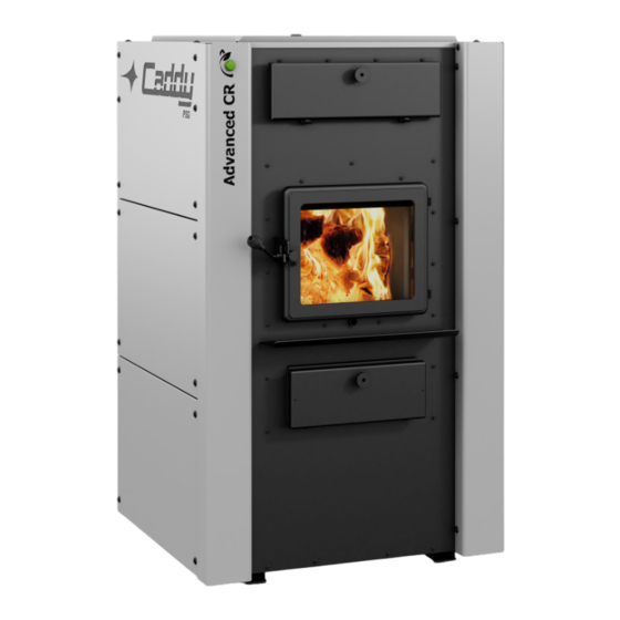
Installation and operating instructions
for the CADDY ADVANCED CR wood furnace
FURNACE MODELS INCLUDED IN THIS MANUAL
Read these instructions carefully before installing
You have purchased one of the finest wood furnaces available on the
market. We are confident that your furnace will provide years of comfort
Verified and tested for Canada and the United States
by an accredited laboratory.
Printed in Canada
Certified according to CSA B415.1-10, CSA B366.1, UL391.
WOOD ONLY | Parallel WOOD ADD-ON
Allowed only in the USA)
and operating your furnace.
CONGRATULATIONS!
and safe operation.
Please save these instructions!
Eco-energy at the
hearth of your home
(PF01021)
This manual is available for free download
on the manufacturer's web site. It is a
copyrighted document. Re-sale is strictly
prohibited. The manufacturer may update
this manual from time to time and cannot be
responsible for problems, injuries, or
damages arising out of the use of
information
contained in any
obtained from unauthorized sources.
Caddy
250, de Copenhague,
St-Augustin-de-Desmaures (Québec)
CANADA G3A 2H3
manual
46366A
2024-04-04
Advertisement
Table of Contents

Related Manuals for PSG CADDY ADVANCED CR


Summary of Contents for PSG CADDY ADVANCED CR
- Page 1 Installation and operating instructions for the CADDY ADVANCED CR wood furnace (PF01021) Certified according to CSA B415.1-10, CSA B366.1, UL391. FURNACE MODELS INCLUDED IN THIS MANUAL WOOD ONLY | Parallel WOOD ADD-ON Allowed only in the USA) Read these instructions carefully before installing and operating your furnace.
-
Page 2: Table Of Contents
DOOR GLASS ................................. 13 ASH DRAWER ................................. 13 ASH GRATE ..................................13 ADDITIONAL FRESH AIR SUPPLY ..........................13 FIREWOOD ....................................15 CADDY ADVANCED CR WOOD FURNACE OR PARALLEL ADD-ON PF01021 ................17 INSTALLATION INSTRUCTIONS ............................18 11.1 BLOWER INSTALLATION ............................... 18 11.2 HOT AIR PLENUM TEMPERATURE PROBE INSTALLATION AND CONNECTION (RTD) .......... - Page 3 15.1.5 SMALL FIRES TO TAKE THE CHILL OFF THE HOME ..................40 15.1.6 LONG LASTING LOW OUTPUT FIRES ......................40 15.1.7 HIGH OUTPUT FIRES FOR COLD WEATHER ....................40 15.1.8 MAXIMUM BURN CYCLE TIMES ........................40 15.2 PROLONGED POWER OUTAGE ............................ 41 THE VENTING SYSTEM ................................
-
Page 4: Introduction
CSA B415.1-10 Standard and EPA 40CFR Part 60, subpart QQQQ (2020 limit). To optimize the efficiency of your furnace, here is some advice that you should follow when installing or operating your Caddy Advanced CR. Respect the local codes (when in doubt, consult your local dealer). -
Page 5: Appliance Performance (1)
APPLIANCE PERFORMANCE Fuel type Dry cordwood Recommended heating area [*] 1,000 to 2,500 ft² (93 à 232 m²) Combustion chamber volume 3.6 ft³ (0.102 m³) Maximum burn time [*] 10 h Maximum input capacity (dry cordwood) 310,000 BTU Overall heat output rate (min. to max.) 19,354 BTU/h to 47,052 BTU/h (5.6 kW to 13.8 kW) Average overall efficiency 76.6% (HHV) -
Page 6: General Features
GENERAL FEATURES Maximum log length 21 in (533 mm) / north-south** Diameter of the flue collar 6 in (152 mm) Recommended connector pipe diameter 6 in (152 mm) Recommended chimney diameter 6 in (152 mm) Required type of chimney CAN/ULC S629, UL 103 HT (2100 °F) Baffle material C-Cast or equivalent Alcove installation... -
Page 7: Specifications
SPECIFICATIONS Color Grey and black Thermostatic control Door type Single, glass with cast iron frame Glass type Ceramic glass Air return plenum - dimensions (Depth or Height) 15 3/4 in Air return plenum - dimension (Width) 24 3/4 in Hot air plenum - dimensions (Depth or Height) 28 5/8 in Hot air plenum - dimension (Width) 24 1/2 in... -
Page 8: Labels
LABELS... -
Page 10: Blower Technical Data
(DIRECT DRIVE) FILTER DEBIT VARIATION PRESSURE CADDY BLOWER MOTOR SPEED (CFM) (°F) MIN. MAX. ADVANCED CR WITH BLOWER / 1/3 PSC CADDY ADVANCED CR DD-10 25" x 14" x 2" 1/2 ECM ADD-ON (PARALLEL) FURNACE DIMENSIONS CADDY ADVANCED CR WITH BLOWER... - Page 11 ) CADDY ADVANCED CR WITH BLOWER EXTENSION (PA08587)
-
Page 12: Chimney And Draft
CHIMNEY AND DRAFT This furnace must be connected to a chimney certified for use with wood burning heating appliances, a 6-inch diameter chimney is recommended. The unit is not to be connected to a chimney being used by another appliance. If the chimney draft exceeds 0.06 IN.W.C., install the barometric draft control that is supplied with the appliance. -
Page 13: Smoke Detector
. During the first year of operation, check the chimney and flues regularly for dirt/creosote build-up. Once you've been able to assess the rate at which the system is clogging up, you'll be able to set up a regular cleaning schedule. Depending on the level of use and the type of wood used, a mid-season cleaning may be necessary. - Page 14 Exhaust blowers located in a firewood storage room must be installed so as not to create negative pressure in the room where the furnace is located. A fresh air supply may be necessary to prevent solid fuel units from smoke spill back into the home. The guidelines for determining whether a combustion air supply is required are not suitable for all situations.
-
Page 15: Firewood
10 FIREWOOD What is good firewood? Good firewood is that which has been cut to the correct length for the furnace, split to a range of sizes and stacked in the open until its moisture content is reduced to 15% to 20%. Tree species The tree species from which the firewood is produced is less important than its moisture content. - Page 16 How to dry firewood Firewood that is not dry enough to burn is the cause of most complaints about wood burning appliances. Constant burning of green or unseasoned wood produces more creosote and involves lack of heat and dirty glass door. See section 16 FURNACE MAINTENANCE for concerns about creosote.
-
Page 17: Caddy Advanced Cr Wood Furnace Or Parallel Add-On Pf01021
INSTALLATION AND OPERATION INSTRUCTIONS CADDY ADVANCED CR WOOD FURNACE OR PARALLEL ADD-ON PF01021... -
Page 18: Installation Instructions
11.2 HOT AIR PLENUM TEMPERATURE PROBE INSTALLATION AND CONNECTION (RTD) On the Caddy Advanced CR, a temperature probe (RTD) must be installed on the left-hand side of the furnace using the bracket provided with the unit. The RTD is a probe that reads the temperature within the hot air plenum and is essential to the proper operation of the unit. -
Page 19: Unit Location
STEP 5: Connect the RTD probe (B) to the furnace terminal block marked “R”. STEP 6: Use the grommets (C) supplied with the manual to attach the wires from the RTD to the furnace. 11.3 UNIT LOCATION For a safe, quiet, and efficient operation, the furnace must be leveled in both directions and evenly supported to ensure stability. -
Page 20: Minimum Clearances To Combustible Materials And Floor Protection
11.4 MINIMUM CLEARANCES TO COMBUSTIBLE MATERIALS AND FLOOR PROTECTION This appliance must be installed in accordance with the instructions on the certification plate affixed to the unit. 11.4.1 MINIMUM CLEARANCES TO COMBUSTIBLE MATERIALS The clearances shown in this section have been established on the basis of safety tests under normal and abnormal operating conditions in accordance with the procedures set out in standards CSA B366.1 (Canada) and UL 391 (U.S.A.). -
Page 21: Minimum Clearances To Combustible Materials For Air Return Duct
11.4.2 MINIMUM CLEARANCES TO COMBUSTIBLES MATERIALS FOR AIR RETURN DUCT The return air duct should be at least equal in size to the return air plenum. The air return duct can be installed at zero clearance to combustibles. 11.4.3 MINIMUM CLEARANCES TO COMBUSTIBLES MATERIALS FOR HOT AIR PLENUM The plenum installed on the furnace must be made of metal in accordance with NFPA 90B, 2-1.3. -
Page 22: Stove Pipe
The Caddy Advanced CR furnace is equipped with a 6" diameter flue that can be installed to a 6" chimney approved for solid fuel appliances (2100°F). If the draft exceeds 0.06 IN. W.C., a barometric damper must be installed (See Draft Damper). - Page 23 Use 45° elbows where possible, rather than 90° elbows. Alternative installations with 90° elbow or tee.
-
Page 24: Electrical Connections
11.6 ELECTRICAL CONNECTIONS The following instructions do not replace those of your local code. Installation and verification of this appliance must be done by a qualified service man. The furnace is fully assembled at the factory and no electrical connections are required other than plugging the power cord into an electrical outlet, connecting the RTD probe and thermostat. -
Page 25: Fresh Air Supply Installation
installation, which must comply with the manufacturer's instructions. The Caddy Advanced CR features a fresh-air intake system that has been tested and certified. The fresh air supply adapter can be installed on either the left or right side of the furnace, depending on the ... -
Page 26: Tool Holder Installation
11.9 TOOL HOLDER INSTALLATION The furnace comes with a tool holder which can be installed on a wall or beam close to the furnace. The components supplied with the furnace are as follows: 1x tool holder (A) 1x shovel (B) 1x poker (C) 1x scraper (D) 1. -
Page 27: Hot Air Plenum
The warm-air supply-duct system must be constructed of materials with a minimum temperature rating of 250°F. 12 PARALLEL INSTALLATION The installation of the Caddy Advanced CR with another furnace using the same hot air ductwork is not permitted in Canada. - Page 28 To do so, the thermostat controlling the existing furnace must be connected to your Caddy Advanced CR interlock terminal. This way, when a heating signal is sent to the existing furnace, the Caddy Advanced CR will receive the same signal, telling it not to turn on, or to go into a shutdown cycle if it is running at the same time of...
-
Page 29: Thermostat Installation
13 THERMOSTAT INSTALLATION In the case of an installation with a PA01106 electric heating unit, PA03060 serial add-on connection or the installation of a heat pump/air conditioner, refer to their respective leaflets to see the different scenarios for thermostat connection. 13.1 WOOD FURNACE ONLY The furnace must be connected to a thermostat. - Page 30 13.1.1 24V THERMOSTAT WIRING Before installing the thermostat, disconnect the furnace from the power supply. Use a minimum of 4-strand 18 AWG thermostat wire. Strip and crimp 2 of the wires with 1/4" female insulated connectors (typically R and C wires). ...
- Page 31 Pass the 2 crimped wires through the grommet and connect them to the transformer. Strip the other end of the 2 wires and connect them to the thermostat's "C" and "R" terminals. The terminal block is located at the ...
- Page 32 When the existing furnace thermostat calls for heat, the Caddy Advanced CR will reduce the combustion rate to minimum. Once the existing furnace thermostat is satisfied, the wood furnace will return to the control of its own thermostat.
-
Page 33: Add-On Furnace
USA ONLY 2. From the thermostat connected to the existing furnace, connect 2 new wires (B) to terminals “R” and “W” of your existing furnace thermostat and attach them to the Caddy Advanced CR add-on terminal block “I”. EXISTING ADD-ON... -
Page 34: Furnace Operation
14 FURNACE OPERATION 14.1 HOW IT WORKS The Caddy Advanced CR furnace features a self-regulated combustion air supply control system. Using two temperature sensors in the combustion chamber that measure temperature in real time, your furnace will automatically adjust the amount of combustion air required to achieve the cleanest, most efficient combustion. -
Page 35: How To Light And Reload The Furnace
14.3 HOW TO LIGHT AND RELOAD THE FURNACE Always keep a maximum of 4 inches of ash in the combustion chamber. Empty the ash drawer weekly to keep the furnace running smoothly. For clean, efficient combustion always keep some space between the logs and leave at least 4 inches of space in front of the logs. -
Page 36: Cold Start And Coal Ember Bed (The Led Button Light Is Off)
14.3.1 COLD START AND COAL EMBER BED LIGHTING (The led button light is OFF) 1. Press reload button before opening the door. 2. Place paper and kindling on top of the ash grate. 3. Place two logs North & South on each side of the kindling. -
Page 37: Hot Ember Bed Reload (The Led Button Light Is On Or Slowly Blinking)
14.3.2 HOT EMBER BED RELOAD (The led button light is ON or slowly blinking) 1. Press reload button before opening the door. 2. Open the door and bring hot embers to the front. 3. Load two logs North & South at the back. -
Page 38: Lighting Fires
14.5 LIGHTING FIRES Each person who heats with wood develops their own favorite method of building and lighting fires. Whatever method you choose, your goal should be to get a hot fire burning quickly. A fire that starts fast produces less smoke and creates less creosote in the chimney. -
Page 39: Maintaining Wood Fires
15 MAINTAINING WOOD FIRES 15.1 GENERAL ADVICE Wood heating is very different than other forms of heating. Do not expect steady heat output from your furnace. It is normal for its temperature to rise after a new load of wood is ignited and for its temperature to gradually decline as the fire progresses. -
Page 40: Control Of The Air Supply
15.1.2 RELOADING WITH EMBERS Press the reload button, place the new load of wood on and behind the embers,not too close to the glass. Close the door. Lighting each new load of wood accomplishes several things: Removes moisture from the wood surface. ... -
Page 41: Prolonged Power Outage
Combustion chamber size Climate zone you live in Quantity of wood loaded Time of year The moisture content of the wood Species of wood you burn Size of the space to be heated Time cycle for the thermostat to call for heat ... -
Page 42: Factory-Built Metal Chimneys
16.3 FACTORY-BUILT METAL CHIMNEYS These are often referred to as “high temperature” chimneys because they have specific characteristics to withstand temperatures that can be created by wood- burning appliances. Factory-built chimneys are tested as a system, with all the components required for installation. The instructions provided with the chimney by its manufacturer are the only reliable source of installation guidelines. -
Page 43: Minimum Chimney Height
16.4 MINIMUM CHIMNEY HEIGHT The top of the chimney should be tall enough to overcome air turbulence caused when wind blows against the home and its roof. The chimney must extend at least 3 ft. (1 m) above the highest point of contact with the roof, and at least 2 ft. -
Page 44: Supply Of Combustion Air
When it is cold outside, the warmer, lighter air in the home tends to rise. This creates a slight pressure difference in the home. Known as, “stack effect”, this produces a slight negative pressure in the lower part of the home (relative to the outside) and a zone of slightly high pressure in the higher part of the home. -
Page 45: Conventional Home
16.6.1 Conventional Home The safest and most reliable supply of combustion air for a wood-burning appliance is from the room in which it is installed. Room air is already preheated so it will not cool the fire, and its availability is unaffected by wind pressures on the home. -
Page 46: Installation Of Single Wall Chimney Connector
16.7.1 INSTALLATION OF SINGLE WALL CHIMNEY CONNECTOR The chimney connector assembly has been called “the weak link” in wood-burning system safety, because failure to install the connector properly (which has happened many times in the past) can result in house fires. The best flue pipe installation is one that runs straight up from the wood-burning appliance to the base of the chimney without any bends. - Page 47 A flue pipe must never pass through a combustible floor or ceiling or through an attic, roof space, closet, or • concealed space. Where passage through a wall or partition of combustible material is desired, the installation must conform to CAN/CSA-B365 and NFPA 211, Installation Code for Solid-Fuel-Burning Appliances and Equipment.
-
Page 48: Furnace Maintenance
17 FURNACE MAINTENANCE Your new furnace will give you years of reliable service if you use and maintain it properly. Some of the internal components of the combustion chamber, such as firebricks, baffles, and air tubes, will wear out over time under intense heat. -
Page 49: Cleaning Door Glass
17.2 CLEANING DOOR GLASS Under normal conditions, your door glass should stay relatively clean. If your firewood is sufficiently dry and you follow the operating instructions in this manual, a whitish, dusty deposit will form on the inner surface of the glass after a week or so of use. -
Page 50: Replacement Of The Glass And Gaskets
17.4 REPLACEMENT OF GLASS AND GASKETS After a year or more of use, the door seal will compress and become hard which can allow air to pass through. You can check the air tightness of your door gasket by closing and locking the door on a piece of paper. The test must be performed all the way around the door. - Page 51 8. Install the new gasket on the glass. Remove some of the paper covering the gasket adhesive. And center the gasket on the edge of the glass so that when folded and glued, the gasket is equal on both sides. Do not stretch the gasket during installation.
-
Page 52: Heat Exchangers Care
17.6 HEAT EXCHANGERS CARE Heat exchangers must be cleaned thoroughly at the end of each heating season. During summer months, air in basements is more humid, and with minimal air circulation within the furnace, it can mix with creosote and/or sooth deposits and form an acid that will accelerate the corrosion process and induce premature decay of the steel. - Page 53 3. Use the scraper provided, clean the three exchanger tubes. 4. Dirt in the lateral exchangers (1 and 3) will fall into the rear of the combustion chamber. 5. Dirt accumulated in the central exchanger (2) will be removed from the front or the rear of the furnace. If you remove dirt from the central exchange to the back of the furnace, disconnect the black pipe connector to dispose of the deposit.
- Page 54 6. Next, check that the baffle is clear of ashes and reposition it in its original position towards the back of the combustion chamber. Important to note that if the baffle is not positioned correctly, the furnace will not operate efficiently. 7.
-
Page 55: Thermocouples Care
17.7 THERMOCOUPLES CARE 1. Move the baffle (A) of the combustion chamber forward. 2. With a brush, carefully clean the surface of the thermocouples. -
Page 56: Chimney Maintenance
3. Then, reposition the baffle (A) back to its original position towards the back of the combustion chamber. Important to note that the furnace will not burn properly if the baffle is not repositioned correctly. 17.8 CHIMNEY MAINTENANCE Wood smoke can condense inside the chimney connector and chimney, forming a flammable deposit called creosote. If creosote is allowed to build up in the venting system, it can ignite all the way up the chimney if the flue reaches ignition temperature Severe chimney fires can damage even the best chimneys. -
Page 57: Smoke Pipe Inspection
17.10 SMOKE PIPE INSPECTION The smoke pipe must be inspected regularly during the heating season. The pipe must be examined carefully to detect any defects or damages. The pipe can be reassembled if no defect is detected, and defective pipe must be replaced immediately. ... -
Page 58: 1In Filter Adapter
2- Align the notch in the left end of the tube with the keyhole of the left air channel. Using a “vise-grip” pair of pliers hold the tube and lock it into place by turning the tube as shown. Make sure the notch reaches the end of the keyway. -
Page 59: Troubleshooting
19 TROUBLESHOOTING In the event of a technical problem, the first thing you can do is a self-diagnostic test to speed up the process with the technical support department. SELF-DIAGNOSTIC PROCESS Press the LED button and maintain pressure until the LED lights up. The light should be solid green (does not blink) •... - Page 60 to be heated. Unbalanced ventilation system. High creosote content, moderate Wet wood, lack of draft. Use dry wood. heat output. Barometric damper not properly Adjust the barometric damper. adjusted. Restriction in the Clean the chimney, flue pipe and ...
-
Page 61: Exploded Diagram And Parts List
20 EXPLODED DIAGRAM AND PARTS LIST... - Page 72 IMPORTANT: THIS IS UP TO DATE INFORMATION. When requesting service or replacement parts for your furnace, please provide the model and the serial number. We reserve the right to change parts due to technological upgrades or availability. Contact an authorized dealer to obtain any of these parts. Never use substitute materials. Use of non- approved parts can result in poor performance and safety hazards.
- Page 73 PART DESCRIPTION PL66192 6'' X 8 1/4'' X 3 1/4'' X 5 17/64'' HD REFRACTORY BRICK PL66190 HD 4 1/2'' X 6'' X 1 1/4'' REFRACTORY BRICK PL36102 3 1/4" X 9'' REFRACTORY BRICK 29001 4'' X 8'' X 1 1/4'' REFRATORY BRICK HD PL36116 3 1/2"...
- Page 74 PART DESCRIPTION PA08523 WIRING KIT FOR SERIAL INSTALLATION 51035 90-370 FAN RELAY 51019 FAN RELAY 90-382 6 PINS 21621 AIR ENTRY HATCH GASKET SE66194 DAMPER ASSEMBLY SE66193 COMPLETE DAMPER KIT 30084 BOLT 1/4-20 X 1/2" GRADE 5 44190 LIMIT SWITCH PL48170 HEAT EXCHANGER SCRAPER PL48171...
- Page 75 PART DESCRIPTION PL66295 LEFT DECORATIVE COLUMN PL66299 RIGHT DECORATIVE COLUMN PL66300 UPPER RIGHT DECORATIVE PANEL PL66302 RIGHT ACCESS JACKET PANEL PL66303 LEFT ACCESS JACKET PANEL PL66293 COVER ELECTRICAL UNIT PL66235 BLOWER ADAPTOR 44258 LINK BOARD...
-
Page 76: Electrical Diagram
21 ELECTRICAL DIAGRAM 21.1 BLOWER HOUSING WITH REGULAR MOTOR 46366A Printed in Canada 2024-04-04... -
Page 77: Blower Box With Ecm Motor
21.2 BLOWER HOUSING WITH ECM MOTOR... -
Page 78: Why Purchase Through An Authorized Caddy Dealer
22 WHY PURCHASE THROUGH AN AUTHORIZED CADDY DEALER? To make sure your Caddy furnace provides comfort and energy savings in your home for many years, your choice of installer is extremely important. An authorized Caddy dealer will ensure that the system is optimized and installed according to standards. -
Page 79: Caddy Limited Lifetime Warranty (Privilege)
Before shipping your unit or defective component to our plant, you must obtain, from your Caddy dealer, an Authorization Number. Any merchandise shipped to our plant without authorization will be refused automatically and returned to sender. CADDY LIMITED LIFETIME WARRANTY (PRIVILEGED) The warranty of the manufacturer extends only to the original consumer purchaser and is not transferable.
Need help?
Do you have a question about the CADDY ADVANCED CR and is the answer not in the manual?
Questions and answers