GE Multilin 850 Instruction Manual
Feeder protection system
Hide thumbs
Also See for Multilin 850:
- Instruction manual (562 pages) ,
- Instruction manual (664 pages)

Subscribe to Our Youtube Channel
Related Manuals for GE Multilin 850


Summary of Contents for GE Multilin 850
- Page 1 Grid Solutions Feeder Protection System Feeder protection and control Instruction manual 850 version: 2.0x GE publication code: 1601-0298-AB (GEK-119591K) *1601-0298-AB*...
- Page 2 The contents of this manual are the property of GE Multilin Inc. This documentation is furnished on license and may not be reproduced in whole or in part without the permission of GE Multilin. The content of this manual is for informational use only and is subject to change without notice.
-
Page 3: Table Of Contents
Table of Contents 1.INTRODUCTION Overview .............................. 1 - 1 Description of the 850 Feeder Protection System............1 - 2 Security Overview..........................1 - 7 850 Order Codes..........................1 - 8 Specifications...........................1 - 11 Device ................................1 - 11 Protection..............................1 - 11 Control ................................. - Page 4 Serial Communications ........................2 - 26 IRIG-B................................2 - 27 3.INTERFACES Front Control Panel Interface......................3 - 2 850 Graphical Display Pages ......................3 - 3 Working with Graphical Display Pages ..................3 - 5 Single Line Diagram..........................3 - 7 Rugged and Membrane Front Panel LEDs ..................3 - 8 Home Screen Icons ..........................3 - 10 Relay Messages............................3 - 11 Target Messages .............................3 - 11...
- Page 5 Custom Configuration..........................4 - 6 Clock ................................4 - 9 Real-time Clock............................4 - 9 PTP Configuration ............................4 - 9 Clock................................4 - 11 SNTP Protocol ............................4 - 12 Security ............................... 4 - 13 Basic Security ............................4 - 14 CyberSentry ..............................4 - 15 Communications ............................ 4 - 23 RS485................................4 - 23 WiFi................................4 - 23 USB ................................4 - 26...
- Page 6 Analog Outputs .............................4 - 106 Protection ............................4 - 108 Feeder Elements...........................4 - 110 Undercurrent (37)..........................4 - 110 Current Elements ..........................4 - 113 Inverse Time Overcurrent Curves....................4 - 114 Percent of Load-To-Trip........................4 - 121 Phase Time Overcurrent Protection (51P)................. 4 - 121 Phase Instantaneous Overcurrent Protection (50P) ............
- Page 7 RTD Trouble.............................4 - 297 Loss of Communications ........................4 - 298 Control.............................. 4 - 300 Setpoint Group............................4 - 300 Local Control Mode (breakers and switches) ................4 - 303 Breaker Control .............................4 - 312 Switch Control (9)..........................4 - 315 Pole Discordance (52) .........................4 - 318 Virtual Input Control..........................4 - 324 Trip Bus..............................4 - 325 Breaker Failure (50BF) ........................4 - 327...
- Page 8 Contact Inputs............................5 - 6 Output Relays.............................5 - 6 Output Relay 1 (TRIP)..........................5 - 6 Output Relay 2 (CLOSE) .......................... 5 - 6 Virtual Inputs............................5 - 7 Virtual Outputs ...........................5 - 8 Flex State ..............................5 - 8 Communications..........................5 - 8 GOOSE Rx and Tx ............................
- Page 9 Digital Counters ..........................7 - 4 Remote Modbus Device ........................ 7 - 5 Clear Records............................. 7 - 7 8.MAINTENANCE Environmental Health Report..................... 8 - 1 General Maintenance........................8 - 3 In-service Maintenance..........................8 - 3 Out-of-service Maintenance ........................8 - 3 Unscheduled Maintenance (System Interruption) ..............8 - 3 A.APPENDIX A Warranty..............................
- Page 10 VIII 850 FEEDER PROTECTION SYSTEM – INSTRUCTION MANUAL...
-
Page 11: Introduction Overview
Grid Solutions 850 Feeder Protection System Chapter 1: Introduction Introduction The Multilin™ 850 relay is a member of the Multilin 8 Series protective relay platform designed for the management, protection and control of feeder applications. The Multilin 850 is used to provide primary (main) or backup protection for underground and overhead feeders for utility and industrial power networks. -
Page 12: Description Of The 850 Feeder Protection System
DESCRIPTION OF THE 850 FEEDER PROTECTION SYSTEM CHAPTER 1: INTRODUCTION Description of the 850 Feeder Protection System Relay functions are controlled by two processors: a Freescale MPC5125 32-bit microprocessor that measures all analog signals and digital inputs and controls all output relays, and a Freescale MPC8358 32-bit microprocessor that controls all the advanced Ethernet communication protocols. - Page 13 CHAPTER 1: INTRODUCTION DESCRIPTION OF THE 850 FEEDER PROTECTION SYSTEM Figure 1-1: Single Line Diagram 21YN 59_2 VTFF Fast Underfrequency 3 CTs UV Restoration 50BF 51_2 50_2 67_2 SOTF* UF Restoration Bus Transfer 50G/ Broken Conductor CT Supervision Harmonic Detection 50G/ 51SG 50SG 67SG Load Encroachment...
- Page 14 DESCRIPTION OF THE 850 FEEDER PROTECTION SYSTEM CHAPTER 1: INTRODUCTION ANSI Device Description 51_2 Negative Sequence Time Overcurrent AC Circuit Breaker Pole Discordance Power Factor Neutral Overvoltage Phase Overvoltage Auxiliary Overvoltage 59_2 Negative Sequence Overvoltage Ground Directional Element 67SG Sensitive Ground Directional Element Neutral Directional Element Phase Directional Element 67_2...
- Page 15 CHAPTER 1: INTRODUCTION DESCRIPTION OF THE 850 FEEDER PROTECTION SYSTEM Description Modbus User Map Neutral Admittance Non-volatile Latches OPC-UA Communications Output Relays Pulsed Outputs Setpoint Groups (6) Trip Bus (6) Transient Recorder (Oscillography) Trip and Close Coil Monitoring Underfrequency Restoration Undervoltage Restoration User-programmable LEDs User-programmable Pushbuttons...
- Page 16 DESCRIPTION OF THE 850 FEEDER PROTECTION SYSTEM CHAPTER 1: INTRODUCTION Figure 1-2: Main Menu Hierarchy Targets S tatus Summary Breakers Switches Last Trip Data Arc Flash Setpoints Device Contact Inputs System Output Relays Inputs Virtual Inputs Outputs Virtual Outputs Flex States Protection Communications Monitoring...
-
Page 17: Security Overview
CHAPTER 1: INTRODUCTION SECURITY OVERVIEW Security Overview The following security features are available: BASIC SECURITY The basic security feature is present in the default offering of the 850 relay. The 850 introduces the notion of roles for different levels of authority. Roles are used as login names with associated passwords stored on the device. -
Page 18: 850 Order Codes
850 ORDER CODES CHAPTER 1: INTRODUCTION When both 850 device and server authentication are enabled, the 850 automatically directs authentication requests to the 850 device or the respective RADIUS server, based on user names. If the user ID credential does not match one of the device local accounts, the 850 automatically forwards the request to a RADIUS server when one is provided. - Page 19 CHAPTER 1: INTRODUCTION 850 ORDER CODES Figure 1-3: 850 Order Codes 850 – * * NN * * A * * N * 850 Feeder Protection System (Standard: English Language, Interface High Voltage Power Supply, Graphical Control Panel) Model Industrial Distribution Feeder Phase Currents - Slot J 1A three-phase current inputs (Slot J) + 4 voltage inputs (J2)
- Page 20 When the advanced communications option is selected, the Ethernet port on the main CPU is disabled. Retrofit order codes must be configured using the GE Multilin Online Store (OLS) based on FASTPATH: the existing relay order code and additional requirements.
-
Page 21: Specifications
CHAPTER 1: INTRODUCTION SPECIFICATIONS Specifications To obtain the total operating time, i.e. from the presence of a trip condition to initiation of a trip, add 8 ms output relay time to the operate times listed below. Device ANNUNCIATOR PANEL Number of Elements: ........1 (36 indicators) Layout:..............Grid of 2x2 or 3x3 Data Storage:............Non-volatile memory Mode:................Self-reset, latched, acknowledgeable... - Page 22 Dropout Level:............102 to 103% of Pickup Level Accuracy: ........... ± 0.5% of reading from 10 to 208 V Undervoltage Curves:........Definite Time, GE IAV Inverse Time or FlexCurves A/B/C/D Pickup Time Delay: ..........0.000 to 6000.000 s in steps of 0.001 s Operate Time: ............
- Page 23 CHAPTER 1: INTRODUCTION SPECIFICATIONS FREQUENCY RATE OF CHANGE (81R) df/dt Trend: ............Increasing, Decreasing, Bi-directional df/dt Pickup Level: ..........0.10 to 15.00 Hz/s in steps of 0.01 Hz/s df/dt Dropout Level:...........96% of Pickup Level df/dt Level Accuracy: ........80 mHz/s or 3.5%, whichever is greater Minimum Frequency: ........20.00 to 80.00 Hz in steps of 0.01 Hz Maximum Frequency:........20.00 to 80.00 Hz in steps of 0.01 Hz Minimum Voltage Threshold:......0.000 to 1.250 x VT in steps of 0.001 x VT...
- Page 24 SPECIFICATIONS CHAPTER 1: INTRODUCTION NEGATIVE SEQUENCE TIME OVERCURRENT (51_2) Operating Parameter: ........I_2 (Fundamental Phasor Magnitude) Pickup Level: ............0.050 to 30.000 x CT in steps of 0.001 x CT Dropout Level:............97 to 98% of Pickup Level Accuracy: ........... For 0.1 to 2.0 x CT:± 0.5% of reading or ±0.4% of rated, whichever is greater For >...
- Page 25 CHAPTER 1: INTRODUCTION SPECIFICATIONS NEUTRAL DIRECTIONAL OVERCURRENT (67N) Directionality: ............Co-existing forward and reverse Polarizing: ...............Voltage, Current, Dual Polarizing Voltage:..........V_0 or VX Polarizing Current: ..........Ig Operating Current: ..........I_0 Level Sensing: ............3 x (|I_0| – K x |I_1|), Ig Restraint, K: ............0.000 to 0.500 in steps of 0.001 Characteristic Angle:.........-90º...
- Page 26 SPECIFICATIONS CHAPTER 1: INTRODUCTION OVERFREQUENCY (81O) Pickup Level: ............20.00 to 65.00 Hz in steps of 0.01 Dropout Level:............Pickup - 0.03 Hz Pickup Time Delay: ..........0.000 to 6000.000 s in steps of 0.001 s Dropout Time Delay:......... 0.000 to 6000.000 s in steps of 0.001 s Minimum Operating Voltage:......
- Page 27 Level Accuracy:............±0.5% of reading from 10 to 208 V Phases Required for Operation: ....Any one, Any two, All three Undervoltage Curves: ........Definite Time, GE IAV Inverse Time or FlexCurves A/B/C/D Pickup Time Delay:..........0.000 to 6000.000 s in steps of 0.001s Operate Time:............<...
- Page 28 SPECIFICATIONS CHAPTER 1: INTRODUCTION SENSITIVE GROUND TIME OVERCURRENT (51SG) Operating Parameter: ........Isg (RMS or Fundamental) Pickup Level: ............0.005 to 3.000 xCT in steps of 0.001 xCT Pickup Level: ............0.005 to 3.000 xCT in steps of 0.001 xCT 0.50 to 15.00 A in steps of 0.01 A (For 50:0.025) Dropout Level:............
- Page 29 CHAPTER 1: INTRODUCTION SPECIFICATIONS SENSITIVE GROUND DIRECTIONAL OVERCURRENT (67SG) Directionality: ............Co-existing forward and reverse Polarizing: ...............Voltage, Current, Dual Polarizing Voltage:..........V_0 or VX Polarizing Current: ..........Ig Operating Current: ..........Isg Level Sensing: ............Ig, Isg Characteristic Angle:.........-90º to 90º in steps of 1° Limit Angle: ............40º...
- Page 30 SPECIFICATIONS CHAPTER 1: INTRODUCTION UNDERCURRENT (37) Operating Parameter: ........Per-phase current Ia, Ib, Ic (Phasor) Trip/Alarm Pickup Level:........0.05 to 0.95 x CT in steps of 0.01 x CT Dropout Level:............102 to 103% of Pickup Trip/Alarm Delay:..........0.00 to 180.00 s in steps of 0.01 s Pickup Accuracy: ..........
-
Page 31: Control
CHAPTER 1: INTRODUCTION SPECIFICATIONS WATTMETRIC GROUND FAULT (32N) Measured Power: ..........zero-sequence Characteristic Angle:.........0º to 359º in steps of 1° Power Pickup Range:.........0.001 to 1.200 CT x VT in steps of 0.001 Pickup Level Accuracy: ........± 1% or ± 0.0025 CT x VT, whichever is greater Hysteresis:..............3% or 0.001 CT x VT, whichever is greater Curve: ...............Definite Time, Inverse Time, or FlexCurve Operating Voltage Pickup Level: ....0.02 to 3.00 x VT in steps of 0.01 x VT... - Page 32 SPECIFICATIONS CHAPTER 1: INTRODUCTION BREAKER FAILURE Mode:................ 3-pole Current Supervision:.......... phase and neutral current (fundamental phasor magnitude) Current Supervision Pickup:......0.050 to 30.000 x CT in steps of 0.001 x CT Current Supervision Dropout: ....... 97 to 98% of pickup Current Supervision Accuracy: ....
-
Page 33: Monitoring
CHAPTER 1: INTRODUCTION SPECIFICATIONS SYNCHROCHECK (25) Maximum Frequency Difference:....0.01 to 5.00 Hz in steps of 0.01 Hz for frequency window of ± 5 Hz Maximum Angle Difference: ......1° to 100° in steps of 1° Maximum Voltage Difference: ......10 to 600000 V in steps of 1 V Hysteresis for Maximum Frequency Difference:............0.01 to 0.10 Hz in steps of 0.01 Hz Breaker Closing Time:........0.000 to 6000.000 s in steps of 0.001 s... -
Page 34: Recording
SPECIFICATIONS CHAPTER 1: INTRODUCTION FAULT REPORTS Number of Reports: ........... 15 Fault Location Method:........Single-ended Voltage Source:............ Wye-connected VTs, Delta-connected VTs and neutral voltage, delta-connected VTs and zero-sequence current (approximation) Maximum Method Accuracy:......Fault resistance is zero or fault currents from all line terminals are in-phase Relay Accuracy: .......... -
Page 35: User-Programmable Elements
CHAPTER 1: INTRODUCTION SPECIFICATIONS EVENT DATA Number of Records:...........1024 (matches the existing Event Recorder) Data Storage:............Non-volatile memory Time-tag Accuracy: ...........One microsecond Settings:..............64 Configurable FlexAnalog parameters, Event Selector Actuals: ..............Selected Event Number, Timestamp of Selected Event, Cause of Selected Event, 64 Configurable FlexAnalog values Commands: ............None (using existing Clear Event Recorder) DATA LOGGER Data Logger channels: ........16... -
Page 36: Metering
SPECIFICATIONS CHAPTER 1: INTRODUCTION FLEXELEMENTS Number of elements: ........8 Operating signal: ..........Any analog actual value, or two values in a differential mode Operating signal mode: ........Signed, or Absolute value Operating mode:..........Level, Delta Comparison direction:........Over, Under Pickup Level: ............ - Page 37 CHAPTER 1: INTRODUCTION SPECIFICATIONS Voltages Parameters:............Wye VTs: A-n, B-n, C-n, A-B, B-C, C-A, Average Phase, Neutral and Residual Delta VTs: A-B, B-C, C-A, Neutral and Residual Accuracy:..............± 0.5% of reading from 15 to 208 V ± 1% for open Delta connections Real Power (Watts) Range: ..............-214748364.8 kW to 214748364.7 kW Parameters:............3-phase;...
-
Page 38: Inputs
SPECIFICATIONS CHAPTER 1: INTRODUCTION CURRENT AND VOLTAGE HARMONICS Parameters:............Magnitude of each harmonic and THD Range:..............2 to 25 harmonic: per-phase displayed as % of f fundamental frequency THD: per-phase displayed as % of f DEMAND Measured Values: ..........Phase A/B/C present and maximum current Measurement Type:........... -
Page 39: Outputs
CHAPTER 1: INTRODUCTION SPECIFICATIONS ARC FLASH SENSOR/FIBER Number of Point Sensors: .......4 Detection Radius:..........180 degree Maximum Fiber Length (Point Sensor): ..18 ft Fiber Size:..............1000 um Mode:................Multi-mode Connector:..............Small Media Interface (SMI) Fiber Type:..............Plastic Optical Fiber Bend Radius: ............>25 mm CONTACT INPUTS Number of Inputs:..........Based on relay ordering Type: .................Wet or Dry Wet Contacts: ............300 V DC maximum... - Page 40 SPECIFICATIONS CHAPTER 1: INTRODUCTION TRIP/CLOSE OUTPUT RELAYS (Relays #1 and #2 from Slot F, Relays #9 and #10 from Slot G) Type: ................. FORM-A Configuration: ............2 (two) electromechanical Contact material:..........silver-alloy Operate time:............<8 ms Continuous current:........... 10 A Make and carry for 0.2s: .........
-
Page 41: Power Supply
CHAPTER 1: INTRODUCTION SPECIFICATIONS Power Supply POWER SUPPLY Nominal DC Voltage: .........125 to 250 V Minimum DC Voltage: ........88 V Maximum DC Voltage: ........300 V Nominal AC Voltage:..........100 to 240 V at 50/60 Hz Minimum AC Voltage:........88 V at 50 to 60 Hz Maximum AC Voltage:........265 V at 50 to 60 Hz Voltage loss ride through: .......20 ms duration POWER SUPPLY (FOR “L”... -
Page 42: Testing & Certification
SPECIFICATIONS CHAPTER 1: INTRODUCTION REMOTE MODBUS DEVICE PROFILE Device Name: ............BSG3 (13 alphanumeric characters maximum) IP Address: ............. 0.0.0.0 – standard Ethernet address Slave Address: ............254 (1 to 254) Modbus Port:............502 (0 to 10000, default 502) Poll Rate: ..............3 minute (OFF, 3 to 120 minutes), the continuous mode poll interval is defined as the poll rate interval Trigger:.............. -
Page 43: Physical
CHAPTER 1: INTRODUCTION SPECIFICATIONS Harmonic Immunity IEC61000-4-13 Class 3 Conducted RF Immunity 0-150kHz IEC61000-4-16 Level 4 Ingress Protection IEC60529 IP54 front Environmental (Cold) IEC60068-2-1 -40C 16 hrs Environmental (Dry heat) IEC60068-2-2 85C 16hrs Relative Humidity Cyclic IEC60068-2-30 6 day humidity variant 2 IEEE/ANSI C37.90.1 4kV, 5 kHz Damped Oscillatory... -
Page 44: Cautions And Warnings
CAUTIONS AND WARNINGS CHAPTER 1: INTRODUCTION Cautions and Warnings Before attempting to install or use the device, review all safety indicators in this document to help prevent injury, equipment damage, or downtime. Safety words and definitions The following symbols used in this document indicate the following conditions Indicates a hazardous situation which, if not avoided, will result in death or serious DANGER: injury. - Page 45 CHAPTER 1: INTRODUCTION CAUTIONS AND WARNINGS Ensure that all ground paths are un-compromised for safety purposes during device operation and service. All recommended equipment that should be grounded and must have a reliable and un-compromised grounding path for safety purposes, protection against electromagnetic interference and proper device operation.
- Page 46 CAUTIONS AND WARNINGS CHAPTER 1: INTRODUCTION LED transmitters are classified as IEC 60825-1 Accessible Emission Limit (AEL) Class CAUTION: 1M. Class 1M devices are considered safe to the unaided eye. Do not view directly with optical instruments. To ensure the settings file inside the relay is updated, wait 30 seconds after a setpoint FASTPATH: change before cycling power.
-
Page 47: Must-Read Information
CHAPTER 1: INTRODUCTION MUST-READ INFORMATION Must-read Information The following general statements apply and are repeated in the relevant sections of the manual. • WiFi and USB do not currently support CyberSentry security. For this reason WiFi is FASTPATH: disabled by default if the CyberSentry option is purchased. The user can enable WiFi, but be aware that doing so violates the security and compliance model that CyberSentry is supposed to provide. -
Page 48: Storage
Customers are responsible for shipping costs to the factory, regardless of whether the unit is under warranty. • Fax a copy of the shipping information to the GE Grid Solutions service department. Use the detailed return procedure outlined at https://www.gegridsolutions.com/multilin/support/ret_proc.htm The current warranty and return information are outlined at https://www.gegridsolutions.com/multilin/warranty.htm... -
Page 49: Product Identification
Grid Solutions 850 Feeder Protection System Chapter 2: Installation Installation Mechanical Installation This section describes the mechanical installation of the system, including dimensions for mounting and information on module withdrawal and insertion. Product Identification The product identification label is located on the side panel of the 850. This label indicates the product model, serial number, and date of manufacture. -
Page 50: Dimensions
MECHANICAL INSTALLATION CHAPTER 2: INSTALLATION Dimensions The dimensions (in inches [millimeters]) of the 850 are shown below. Additional dimensions for mounting, and panel cutouts, are shown in the following sections. Figure 2-2: 850 Dimensions 2–2 850 FEEDER PROTECTION SYSTEM – INSTRUCTION MANUAL... -
Page 51: Mounting
CHAPTER 2: INSTALLATION MECHANICAL INSTALLATION Mounting The unit can be mounted two ways: standard panel mount or optional tab mounting, if required. • Standard panel mounting: From the front of the panel, slide the empty case into the cutout. From the rear of the panel, screw the case into the panel at the 8 screw positions (see figures in Standard panel mount section). -
Page 52: Standard Panel Mount
MECHANICAL INSTALLATION CHAPTER 2: INSTALLATION Standard Panel Mount The standard panel mount and cutout dimensions are illustrated below. To avoid the potential for personal injury due to fire hazards, ensure the unit is CAUTION: mounted in a safe location and/or within an appropriate enclosure. Figure 2-4: Standard panel mount Figure 2-5: Panel cutout dimensions 2–4... -
Page 53: Depth Reducing Collar
• 18J0-0029 8 Series Depth Reducing Collar - 3" Figure 2-6: Depth reducing collar dimensions 8.73 7.25 9.00 10.40 Dimensions in inches GE PN 'A' DEPTH 1009-0310 1 3/8" 1009-0311 3" 892703A1.dwg Figure 2-7: Depth reducing collar panel cutout 3.86 3.86... - Page 54 8-32x3/8IN P/HD PHIL BLK GE PART# 1408-0306 (qty:16) Tightening Torque: 15 in lb (1.7 Nm) DEPTH REDUCING COLLAR GE PART# 1009-0311 3IN (76.2MM) DEPTH GE PART# 1009-0310 1.375IN (34.9MM) DEPTH 8 SERIES UNIT 892703A1.dwg To mount an 8 Series relay with a depth reducing collar, follow these steps:...
-
Page 55: Draw-Out Unit Withdrawal And Insertion
CHAPTER 2: INSTALLATION MECHANICAL INSTALLATION Draw-out Unit Withdrawal and Insertion Unit withdrawal and insertion may only be performed when control power has been removed from the unit. Turn off control power before drawing out or re-inserting the relay to prevent mal- FASTPATH: operation. -
Page 56: Removable Power Supply
MECHANICAL INSTALLATION CHAPTER 2: INSTALLATION Removable Power Supply Follow the steps outlined in the Insert or Remove Power Supply diagram to insert (#1) or remove (#2) the power supply from the unit. Figure 2-10: Insert or Remove the Power Supply Figure 2-11: Unlatch Module (location is marked by arrow) 2–8 850 FEEDER PROTECTION SYSTEM –... -
Page 57: Removable Magnetic Module
CHAPTER 2: INSTALLATION MECHANICAL INSTALLATION Removable Magnetic Module Follow the steps outlined in the diagram below to insert or remove the magnetic module from the unit. Figure 2-12: Insert or Remove the Magnetic Module 850 FEEDER PROTECTION SYSTEM – INSTRUCTION MANUAL 2–9... -
Page 58: Arc Flash Sensor
MECHANICAL INSTALLATION CHAPTER 2: INSTALLATION Arc Flash Sensor The Arc Flash sensor houses the fiber optics and membrane that are used to detect the arc flash. Two mounting screw holes are provided to affix the sensors to the panel. If the 8 Series is used in the computation for reducing the Hazard Reduction Category CAUTION: code, operands for sensor failures must be assigned to an auxiliary output relay which must be connected into the control logic of the breaker equipment to ensure safe... -
Page 59: Electrical Installation
CHAPTER 2: INSTALLATION ELECTRICAL INSTALLATION Sensor fiber should be held in place loosely for the best long-term performance. Avoid over-tightening ties which may deform or break the sensor fiber. Before installing the AF sensor unit, ensure that all other drilling and installation is complete to minimize possible damage to the sensitive unit. - Page 60 ELECTRICAL INSTALLATION CHAPTER 2: INSTALLATION Figure 2-14: Typical wiring diagram – Draw-out unit DIRECTION OF POWER FLOW FOR POSITIVE WATTS POSITIVE DIRECTION OF LAGGING VARS PHASE CTs SEE GROUND INPUT WIRING IN INSTRUCTION MANUAL CURRENT INPUTS VOLTAGE INPUTS DIGITAL INPUT 1 DIGITAL INPUT 2 DIGITAL INPUT 3 DIGITAL INPUT 4...
-
Page 61: Terminal Identification
CHAPTER 2: INSTALLATION ELECTRICAL INSTALLATION Terminal Identification All the terminal strips are labeled with a slot letter to identify the module slot position and numbers to identify the terminals within the module. Make sure that the first letter on the terminal strip corresponds to the slot location CAUTION: identified on the chassis silkscreen. - Page 62 ELECTRICAL INSTALLATION CHAPTER 2: INSTALLATION Figure 2-17: INCORRECT INSTALLATION METHOD (lower lug reversed) A broad range of applications are available for the 850 relays. As such, it is not possible to present typical connections for all possible schemes. The information in this section covers the important aspects of interconnections, in the general areas of instrument transformer inputs, other inputs, outputs, communications and grounding.
- Page 63 CHAPTER 2: INSTALLATION ELECTRICAL INSTALLATION Figure 2-18: Rear Terminal Layout of the 8 Series Platform BASIC COMMS COMMS PORT 4 PORT 5 PORT 1 BANK - J1 BANK - K1 BANK - J2 BANK - K2 AC ANALOG INPUTS Table 2-1: Power Supply H - HV Power Supply Terminal Description...
- Page 64 ELECTRICAL INSTALLATION CHAPTER 2: INSTALLATION Table 2-2: Power Supply L - LV Power Supply Terminal Description (DC Voltage input polarity) +ve (positive) -ve (negative) Ground Table 2-3: Comms SE - Comms - Basic Ethernet 1E/1P/2E/2A - Comms - Advanced Ethernet Terminal Description Terminal...
-
Page 65: Wire Size
CHAPTER 2: INSTALLATION ELECTRICAL INSTALLATION FC_3 NC Critical Fail Relay FC_3 COM Critical Fail Relay FC_3 NO Critical Fail Relay Table 2-5: AC Analog AC Inputs - 4 X 1/5A CT, 4 VT AC Inputs - 1 X 1/5A CT Terminal Description Terminal... -
Page 66: Phase Sequence And Transformer Polarity
ELECTRICAL INSTALLATION CHAPTER 2: INSTALLATION Phase Sequence and Transformer Polarity For correct operation of the relay features, follow the instrument transformer polarities, shown in the Typical Wiring Diagram above. Note the solid square markings that are shown with all instrument transformer connections. When the connections adhere to the drawing, the arrow shows the direction of power flow for positive watts and the positive direction of vars. - Page 67 CHAPTER 2: INSTALLATION ELECTRICAL INSTALLATION Figure 2-20: Ground Inputs Figure 2-21: Sensitive Ground Inputs 850 FEEDER PROTECTION SYSTEM – INSTRUCTION MANUAL 2–19...
-
Page 68: Voltage Inputs
ELECTRICAL INSTALLATION CHAPTER 2: INSTALLATION Voltage Inputs The 850 relays have four channels for AC voltage inputs, each with an isolating transformer. Voltage transformers up to a maximum 5000:1 ratio may be used. The nominal secondary voltage must be in the 10 to 240 V range. In Main-Tie-Main bus transfer scheme, the three phase inputs are mostly used for “Bus voltage”. -
Page 69: Zero-Sequence Ct Installation
CHAPTER 2: INSTALLATION ELECTRICAL INSTALLATION Figure 2-23: Restricted Ground Fault Inputs Zero-Sequence CT Installation The figure below shows the various CT connections and the exact placement of a Zero Sequence current CT, so that ground fault current can be detected. Twisted pair cabling on the Zero Sequence CT is recommended. -
Page 70: Control Power
ELECTRICAL INSTALLATION CHAPTER 2: INSTALLATION Control Power Control power is supplied to the relay such that it matches the relay’s installed power supply range. Control power supplied to the relay must match the installed power supply range. If the CAUTION: applied voltage does not match, damage to the unit may occur. -
Page 71: Output Relays
CHAPTER 2: INSTALLATION ELECTRICAL INSTALLATION Figure 2-26: Wet and Dry Contact Input Wiring Examples INPUT SIGNAL SWITCH (WET) INPUT SIGNAL SWITCH (DRY) EXTERNAL DC POWER SUPPLY Output Relays The locations of the output relays have a fixed assignment for the platform called the master identifier. - Page 72 ELECTRICAL INSTALLATION CHAPTER 2: INSTALLATION Slots F,G,H Terminal Master Identifier Slots F,G,H with I/O options A,A,N Terminal # SLOT F SLOT G SLOT H Terminal # SLOT F SLOT G RELAY_5 RELAY_13 RELAY_21 Digital In_1 Digital In_8 RELAY_5 RELAY_13 RELAY_21 Digital In_2 Digital In_9 RELAY_5...
- Page 73 CHAPTER 2: INSTALLATION ELECTRICAL INSTALLATION Table 2-8: Slots F,G,H with I/O options A,A,F (left) and I/O options A, N, F (right) Slots F,G,H with I/O options A,A,F Slots F,G,H with I/O options A,N,F Terminal # SLOT F SLOT G SLOT H Terminal # SLOT F SLOT H...
-
Page 74: Serial Communications
ELECTRICAL INSTALLATION CHAPTER 2: INSTALLATION Serial Communications One two-wire RS485 port is provided. Up to thirty-two 8 Series IEDs can be daisy-chained together on a communication channel without exceeding the driver capability. For larger systems, additional serial channels must be added. Commercially available repeaters can also be used to add more than 32 relays on a single channel. -
Page 75: Irig-B
CHAPTER 2: INSTALLATION ELECTRICAL INSTALLATION IRIG-B IRIG-B is a standard time code format that allows time stamping of events to be synchronized among connected devices within 1 millisecond. The IRIG-B time code formats are serial, width-modulated codes which can be either DC level shift or amplitude modulated (AM) form. - Page 76 ELECTRICAL INSTALLATION CHAPTER 2: INSTALLATION 2–28 850 FEEDER PROTECTION SYSTEM – INSTRUCTION MANUAL...
- Page 77 Grid Solutions 850 Feeder Protection System Chapter 3: Interfaces Interfaces There are two methods of interfacing with the 850. • Interfacing via the relay keypad and display. • Interfacing via the EnerVista 8 Series Setup software. This section provides an overview of the interfacing methods available with the 850 using the relay control panel and EnerVista 8 Series Setup software.
- Page 78 FRONT CONTROL PANEL INTERFACE CHAPTER 3: INTERFACES Front Control Panel Interface The relay provides an easy to use faceplate for menu navigation through 5 navigation pushbuttons and high quality graphical display. Conveniently located on the panel is a group of 7 pushbuttons for Up/Down value selection, “Enter” “Home”, “Escape”, “Help”, and “Reset”...
-
Page 79: Interfaces Front Control Panel Interface
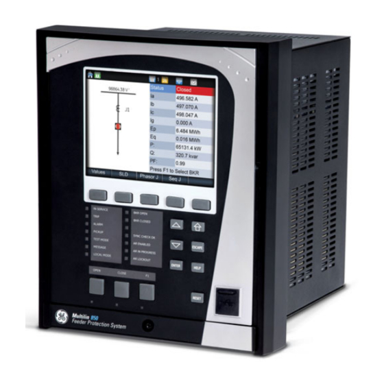
CHAPTER 3: INTERFACES FRONT CONTROL PANEL INTERFACE Figure 3-2: Front Control Panel The USB port is intended for connection to a portable computer. 850 Graphical Display Pages The front panel liquid crystal display (LCD) allows visibility under varied lighting conditions. When the keypad and display are not being used, system information is displayed after a user-defined period of inactivity. - Page 80 FRONT CONTROL PANEL INTERFACE CHAPTER 3: INTERFACES Figure 3-3: 850 Display Page Hierarchy Targets S tatus Summary Breakers Switches Last Trip Data Arc Flash Setpoints Device Contact Inputs System Output Relays Inputs Virtual Inputs Outputs Virtual Outputs Flex States Protection Communications Monitoring Information...
-
Page 81: Working With Graphical Display
CHAPTER 3: INTERFACES FRONT CONTROL PANEL INTERFACE Working with The display contains five main menu items labeled Targets, Status, Metering, Setpoints, Graphical Display and Records located at the bottom of the screen. Choosing each main menu item displays the corresponding sub-menu. Pages Figure 3-4: Typical paging operation from the main menu There are two ways to navigate throughout the 850 menu: using the pushbuttons... - Page 82 FRONT CONTROL PANEL INTERFACE CHAPTER 3: INTERFACES The tab pushbuttons are used to enter the menu corresponding to the label on the tabs. If more than 5 tabs exist, the first and the last tab are labelled with arrows to allow you to scroll to the other tabs.
-
Page 83: Single Line Diagram
CHAPTER 3: INTERFACES FRONT CONTROL PANEL INTERFACE The Up, Down, Left, and Right pushbuttons on the membrane faceplate are used to move the yellow highlight. These pushbuttons are also used on special screens to navigate to multiple objects. The Escape pushbutton is used to display the previous menu. This pushbutton can also be used to cancel a setpoint change. -
Page 84: Rugged And Membrane Front Panel Leds
FRONT CONTROL PANEL INTERFACE CHAPTER 3: INTERFACES The breaker status icon changes state according to the breaker status input and the color of the icon changes in accordance with the color scheme setting ( Setpoints > Device > Front Panel > Display Properties > Color Scheme Breaker Status Color Scheme Open Color Close Color Not Configured Unknown Disconnected Red (Open) - Page 85 CHAPTER 3: INTERFACES FRONT CONTROL PANEL INTERFACE Figure 3-9: Typical LED Indicator Panel BKR OPEN IN SERVICE TRIP BKR CLOSED ALARM SYNCHECK OK PICK UP AR ENABLED TEST MODE AR IN PROGRESS MESSAGE LOCAL MODE AR LOCKOUT Some status indicators are common while some are feature specific which depend on the availability in the order code.
-
Page 86: Home Screen Icons
FRONT CONTROL PANEL INTERFACE CHAPTER 3: INTERFACES Default labels are shipped in the package of every 850, together with custom templates. A custom LED template is available for editing and printing, refer to publication GET-20035 from http://www.gegridsolutions.com/multilin. The default labels can be replaced by user- printed labels. -
Page 87: Relay Messages
CHAPTER 3: INTERFACES FRONT CONTROL PANEL INTERFACE Table 3-5: Breaker Health Icon Description The Breaker Health icon is blue when the setting for the breaker health function is not disabled. When the setting is disabled the icon is grey. Table 3-6: Settings Save Icon Description Indicates that a setting is being saved on the relay (i.e., when changing one of relay settings). -
Page 88: Self-Test Errors
FRONT CONTROL PANEL INTERFACE CHAPTER 3: INTERFACES Target Messages can be cleared either by pressing the PB corresponding to the tab “CLEAR”, or by initiating a RESET command. The “CLEAR” command clears only the Target Messages, while initiating a RESET clears not only the Target Messages, but also any latched LEDs and output relays. - Page 89 CHAPTER 3: INTERFACES FRONT CONTROL PANEL INTERFACE Figure 3-12: Major Errors Table 3-8: Minor Self-test Errors Self-test Error Description of Problem How Often the Test is What to do Performed Message Order Code Error Hardware doesn’t Every 1 second If alert doesn’t self-reset then match order code contact factory.
- Page 90 FRONT CONTROL PANEL INTERFACE CHAPTER 3: INTERFACES Self-test Error Description of Problem How Often the Test is What to do Performed Message WiFi Default SSID and Passphrase is Every 1 second Set SSID and Passphrase Settings the factory default Link Error Primary Port 1 or Port 4 Every 1 second Ensure Ethernet cable is...
-
Page 91: Out Of Service
CHAPTER 3: INTERFACES FRONT CONTROL PANEL INTERFACE 3.To disable Link Error Primary target when not in-use with SE order code, change IP address to 127.0.0.1 Table 3-9: Major Self-test Errors Self-test Error Latched Description of How Often the Test What to do Message Target Problem... - Page 92 FRONT CONTROL PANEL INTERFACE CHAPTER 3: INTERFACES Slide the label removal tool under the LED label as shown in the next image. Make sure the bent tabs are pointing away from the relay. Move the tool inside until the tabs enter the pocket.
-
Page 93: Software Interface
At least 2 GB of RAM is installed. • 1280 x 800 display screen The software can be installed from either the GE EnerVista CD or the GE Multilin website at http://www.gegridsolutions.com/. 850 FEEDER PROTECTION SYSTEM – INSTRUCTION MANUAL 3–17... -
Page 94: Installing The Enervista 8 Series Setup Software
Installing the After ensuring the minimum requirements indicated earlier, use the following procedure to EnerVista 8 Series install the EnerVista 8 Series Setup software from the enclosed GE EnerVista CD. Setup Software Insert the GE EnerVista CD into your CD-ROM drive. - Page 95 CHAPTER 3: INTERFACES SOFTWARE INTERFACE Select the complete path, including the new directory name, where the EnerVista 8 Series Setup software is being installed. Click on Next to begin the installation. The files are installed in the directory indicated, the USB driver is loaded into the computer, and the installation program automatically creates icons and adds the EnerVista 8 Series Setup software to the Windows start menu.
-
Page 96: Upgrading The Software
SOFTWARE INTERFACE CHAPTER 3: INTERFACES 13. Select USB as the Interface type. 14. Select the Read Order Code button. Upgrading the The latest EnerVista software and firmware can be downloaded from: Software https://www.gegridsolutions.com/ After upgrading, check the version number under Help > About. If the new version does not display, try uninstalling the software and reinstalling the new versions. -
Page 97: Connecting Enervista 8 Series Setup Software To The Relay
CHAPTER 3: INTERFACES SOFTWARE INTERFACE Connecting EnerVista 8 Series Setup software to the Relay Using the Quick The Quick Connect button can be used to establish a fast connection through the front Connect Feature panel USB port of a relay, or through the Ethernet port. The following window appears when the QuickConnect button is pressed: As indicated by the window, the "Quick Connect"... - Page 98 SOFTWARE INTERFACE CHAPTER 3: INTERFACES When connected, a new Site called “Quick Connect” appears in the Site List window. The Site Device has now been configured via the Quick Connect feature for either USB or Ethernet communications. Proceed to Connecting to the Relay next, to begin communications.
-
Page 99: Configuring Ethernet Communications
FASTPATH: Install and start the latest version of the EnerVista 8 Series Setup software (available from the GE EnerVista CD or Website). See the previous section for the installation procedure. Click on the Device Setup button to open the Device Setup window and click the Add Site button to define a new site. -
Page 100: Connecting To The Relay
SOFTWARE INTERFACE CHAPTER 3: INTERFACES 10. Click OK when the relay order code has been received. The new device will be added to the Site List window (or Online window) located in the top left corner of the main EnerVista 8 Series Setup software window. The 850 Site Device has now been configured for Ethernet communications. -
Page 101: Working With Setpoints & Setpoints Files
CHAPTER 3: INTERFACES SOFTWARE INTERFACE If the status indicator is red, verify that the serial, USB, or Ethernet cable is properly connected to the relay, and that the relay has been properly configured for communications (steps described earlier). The settings can now be edited, printed, or changed. Other setpoint and command windows can be displayed and edited in a similar manner. -
Page 102: File Support
SOFTWARE INTERFACE CHAPTER 3: INTERFACES For setpoints requiring non-numerical pre-set values (e.g. Phase VT Connection below), clicking anywhere within the setpoint value box displays a drop-down selection menu arrow. Select the desired value from this list. In the Setpoints > System Setup > Voltage Sensing dialog box, click on Save to save the values into the 850. -
Page 103: Using Setpoints Files
CHAPTER 3: INTERFACES SOFTWARE INTERFACE Using Setpoints Files The software interface supports three ways of handling changes to relay settings: • In off-line mode (relay disconnected) to create or edit relay settings files for later download to communicating relays. • Directly modifying relay settings while connected to a communicating relay, then saving the settings when complete. - Page 104 SOFTWARE INTERFACE CHAPTER 3: INTERFACES In the offline pane, right-click on Files and select the Add Existing Settings File item as shown: The Open dialog box will appear, prompting the user to select a previously saved setpoint file. As for any other MS Windows® application, browse for the file to be added then click Open.
-
Page 105: Creating A New Setpoints File
CHAPTER 3: INTERFACES SOFTWARE INTERFACE Creating a New The software allows the user to create new setpoint files independent of a connected Setpoints File device. These can be uploaded to a relay at a later date. The following procedure illustrates how to create new setpoint files. -
Page 106: Upgrading Setpoints Files To A New Revision
SOFTWARE INTERFACE CHAPTER 3: INTERFACES Upgrading Setpoints It is often necessary to upgrade the revision for a previously saved setpoint file after the Files to a New 850 firmware has been upgraded. This is illustrated in the following procedure: Revision Establish communications with the 850 relay. -
Page 107: Printing Setpoints
CHAPTER 3: INTERFACES SOFTWARE INTERFACE Printing Setpoints The software allows the user to print partial or complete lists of setpoints. Use the following procedure to print a list of setpoints: Select a previously saved setpoints file in the File pane or establish communications with a device. -
Page 108: Printing Values From A Connected Device
SOFTWARE INTERFACE CHAPTER 3: INTERFACES Printing Values from a A complete list of actual values can also be printed from a connected device with the Connected Device following procedure: Establish communications with the desired device. From the main window, select the Online > Print Device Information menu item The Print/Export Options dialog box will appear. -
Page 109: Uninstalling Files And Clearing Data
CHAPTER 3: INTERFACES SOFTWARE INTERFACE Uninstalling Files and The unit can be decommissioned by turning off the power to the unit and disconnecting Clearing Data the wires to it. Files can be cleared after uninstalling the EnerVista software or the relay, for example to comply with data security regulations. - Page 110 SOFTWARE INTERFACE CHAPTER 3: INTERFACES Quick Setup is designed to allow quick and easy user programming. Power system parameters, and settings for some simple overcurrent elements are easily set. The Quick Setup screen is shown as follows: Figure 3-15: Quick Setup window •...
-
Page 111: Upgrading Relay Firmware
To upgrade the 850 firmware, follow the procedures listed in this section. Upon successful completion of this procedure, the 850 will have new firmware installed with the factory default setpoints.The latest firmware files are available from the GE Grid Solutions website at http://www.gegridsolutions.com. -
Page 112: Loading New Relay Firmware
SOFTWARE INTERFACE CHAPTER 3: INTERFACES Loading New Relay Loading new firmware into the 850 flash memory is accomplished as follows: Firmware Connect the relay to the local PC and save the setpoints to a file as shown in Downloading and Saving Setpoints Files. Select the Maintenance >... - Page 113 CHAPTER 3: INTERFACES SOFTWARE INTERFACE The following screen appears, click YES to proceed with the firmware loading process. 850 FEEDER PROTECTION SYSTEM – INSTRUCTION MANUAL 3–37...
- Page 114 SOFTWARE INTERFACE CHAPTER 3: INTERFACES After the Boot 2 upload is completed, the EnerVista 8 Series Setup software requests the user reboot the relay. After the Boot 1 upload is completed, the EnerVista 8 Series Setup software again requests the user to reboot the relay. Make sure to reboot the relay first and then press the OK.
-
Page 115: Advanced Enervista 8 Series Setup Software Features
The SLD pages can also be saved individually as local XML files. The locally stored XML files can then be reloaded to generate another diagram. SLDs represent objects using GE symbols (similar to ANSI). Figure 3-17: Template SLD 850 FEEDER PROTECTION SYSTEM –... - Page 116 The control objects consist of selectable breakers and disconnect switches. The following figure shows the different symbols in the GE Standard style and IEC style. If the switching element is tagged, blocked, or bypassed, indicators with the letters “T”, “B”, and “By”...
- Page 117 CHAPTER 3: INTERFACES SOFTWARE INTERFACE Figure 3-19: Control Object Symbols The control objects status follows the color scheme from the Setpoints > Device > Front setting. By default, this setting is set to “Green Panel > Display Properties > Color Scheme (open)”.
- Page 118 Blocked” signal in both On and Off state. Figure 3-21: Reclose Blocked signal In addition, Remote Breaker status objects are added for GE and IEC style. Remote breaker status allows monitoring of three distant breakers. These objects are not controllable and hence cannot be used for selection and operation.
- Page 119 CHAPTER 3: INTERFACES SOFTWARE INTERFACE Figure 3-22: Metering Element on configured SLD Device Status Object The configurable SLD feature in the 8 Series allows only one device status object per SLD page. The device status does not have any properties. It is simply shown as “Status: [device status]”.
- Page 120 SOFTWARE INTERFACE CHAPTER 3: INTERFACES and switches on the screen. Pressing up key rotates through in a reverse order. With the membrane front panel, the up, down, left, and right keys can navigate to the closest breaker/switch depending on the key press direction. Rugged Membrane Front Panel...
- Page 121 CHAPTER 3: INTERFACES SOFTWARE INTERFACE If upgrading from firmware 1.7x or earlier, the breaker operations from the front panel now NOTE: follow select-before-operate mechanism. The breaker must be first selected by browsing and pressing Enter key for selection. Once selected, the breaker can be opened or closed with the open and close pushbuttons.
-
Page 122: Flexcurve Editor
SOFTWARE INTERFACE CHAPTER 3: INTERFACES FlexCurve Editor The FlexCurve Editor is designed to allow the user to graphically view and edit the FlexCurve. The FlexCurve Editor screen is shown as follows: • The Operate Curves are displayed, which can be edited by dragging the tips of the curves •... -
Page 123: Transient Recorder (Waveform Capture)
CHAPTER 3: INTERFACES SOFTWARE INTERFACE Transient Recorder The software can be used to capture waveforms (or view trace memory) from the relay at (Waveform Capture) the instance of a pickup, trip, alarm, or other condition. • With software running and communications established, select the Records > Transients >... - Page 124 SOFTWARE INTERFACE CHAPTER 3: INTERFACES TRIGGER TIME & DATE Displays the time and date of the Trigger. DELTA VECTOR DISPLAY SELECT CURSOR LINE POSITION Indicates time difference Indicates the cursor line position Click here to open a new graph between the two cursor in time with respect to the to display vectors.
- Page 125 CHAPTER 3: INTERFACES SOFTWARE INTERFACE Preference Button The following window appears: Change the color of each graph as desired, and select other options as required, by checking the appropriate boxes. Click OK to store these graph attributes, and to close the window.
- Page 126 SOFTWARE INTERFACE CHAPTER 3: INTERFACES 3–50 850 FEEDER PROTECTION SYSTEM – INSTRUCTION MANUAL...
-
Page 127: Protection Summary
CHAPTER 3: INTERFACES SOFTWARE INTERFACE Protection Summary Protection Summary is a single screen which holds the summarized information of different settings from Grouped Elements and Monitoring Elements. The Protection Summary Screen allows the user to: • view the output relay (R3, R4) assignments for the elements •... - Page 128 SOFTWARE INTERFACE CHAPTER 3: INTERFACES 3–52 850 FEEDER PROTECTION SYSTEM – INSTRUCTION MANUAL...
-
Page 129: Offline Settings File Conversion
CHAPTER 3: INTERFACES SOFTWARE INTERFACE Offline Settings File Conversion The EnerVista 8 Series Setup software supports conversion of offline settings files created in the SR Series platform. The feature allows users, who have SR devices, to convert their existing 750 offline settings files to 8 Series files and write them to their 850 devices. The EnerVista 8 Series Setup software reduces the manual effort required when moving from an older product to the 850. -
Page 130: Conversion Summary Report
SOFTWARE INTERFACE CHAPTER 3: INTERFACES To select the SR settings file used for initialization, click the Initialize Settings from SR Settings File button. To locate and select the file to convert, click the button beside the Initialize Settings from SR Settings File box. EnerVista 8 Series Setup version 1.2x and above supports conversion of all 750/760 CAUTION: files as long as they are from a 32-bit PC. - Page 131 CHAPTER 3: INTERFACES SOFTWARE INTERFACE The status icon shows the conversion results: Manual configuration required Successful conversion Value is not supported If desired, the conversion summary report can be printed using the File/Print Print Report command in the EnerVista taskbar or it can be printed from the “GUI” print button. Although the report shows successful conversion (green checkbox), the settings must still NOTE: be verified before putting the relay in service.
- Page 132 SOFTWARE INTERFACE CHAPTER 3: INTERFACES 3–56 850 FEEDER PROTECTION SYSTEM – INSTRUCTION MANUAL...
-
Page 133: Setpoints Setpoints Main Menu
Grid Solutions 850 Feeder Protection System Chapter 4: Setpoints Setpoints Setpoints Main Menu The 850 has a considerable number of programmable setpoints, all of which make the relay extremely flexible. These setpoints have been grouped into a variety of menus which are available from the paths shown below. -
Page 134: Setpoints Entry Methods
Any of these methods can be used to enter the same information. A computer, however, makes entry much easier. Files can be stored and downloaded for fast, error free entry when a computer is used. To facilitate this process, the GE EnerVista CD with the EnerVista 4–2... -
Page 135: Common Setpoints
CHAPTER 4: SETPOINTS SETPOINTS MAIN MENU 8 Series Setup software is supplied with the relay. The relay leaves the factory with setpoints programmed to default values, and it is these values that are shown in all the setpoint message illustrations. At a minimum, the setpoints must be entered for the system to SETPOINTS / SYSTEM... -
Page 136: Logic Diagrams
SETPOINTS MAIN MENU CHAPTER 4: SETPOINTS • TDM: The setting provides a selection for Time Dial Multiplier which modifies the operating times per the selected inverse curve. For example, if an IEEE Extremely Inverse curve is selected with TDM=2, and the fault current is 5 times bigger than the PKP level, operation of the element can not occur before an elapsed time of 2.59 s from Pickup. -
Page 137: Setpoints Text Abbreviations
CHAPTER 4: SETPOINTS SETPOINTS MAIN MENU comparison can only be performed if a logic ‘1’ is provided at the ‘RUN’ input. The relationship between a setpoint and input parameter is indicated by the following symbols: “<” (less than), “>” (greater than), etc. •... -
Page 138: Device
DEVICE CHAPTER 4: SETPOINTS Device Figure 4-3: Device Display Hierarchy Custom Configuration Real Time Clock Modbus Protocol Security RS485 Communications Device Wi-Fi Transient Recorder System Ethernet Inputs Data Logger Routing Outputs Fault Report DNP Protocol Protection Event Data DNP/IEC 104 Points List IEC 60870-5-104 Monitoring Flex States... - Page 139 CHAPTER 4: SETPOINTS DEVICE Simplified configuration mode does not remove any functionality or setting from the device. It only controls the view or display of the settings. All the settings made in Regular configuration mode are still applied during simplified mode (they are either hidden or read-only).
- Page 140 DEVICE CHAPTER 4: SETPOINTS Example 2: More about the Function/Feature view control The differences in the Input setpoints screens for Regular and Simplified mode are shown below. Under Simplified mode, the Virtual Inputs and Remote Inputs are hidden for any configuration change.
-
Page 141: Ptp Configuration
CHAPTER 4: SETPOINTS DEVICE Clock Real-time Clock Path: Setpoints > Device > Real Time Clock The 850 is capable of receiving a time reference from several time sources in addition to its own internal clock for the purpose of time-stamping events, transient recorders and other occurrences within the relay. - Page 142 DEVICE CHAPTER 4: SETPOINTS PORT 4(5) PATH DELAY ASYMMETRY Range: -1000 to +1000 ns in steps of 1 ns Default: 0 ns The setting corresponds to “Delay Asymmetry” in PTP, which is used by the peer delay mechanism to compensate for any difference in the propagation delay between the two directions of a link.
-
Page 143: Clock
CHAPTER 4: SETPOINTS DEVICE PTP VLAN ID Range: 0 to 4095 Default: 0 The setting selects the value of the ID field in the 802.1Q VLAN tag in request messages issued by the relay’s peer delay mechanism. It is provided in compliance with PP (Power Profile). -
Page 144: Sntp Protocol
DEVICE CHAPTER 4: SETPOINTS DST START HOUR Range: 0 to 23 Default: 2 DST END MONTH Range: January to December (all months) Default: Not Set DST END WEEK Range: 1st, 2nd, 3rd, 4th, Last Default: Not Set DST END DAY Range: SUN to SAT (all days of the week) Default: Not Set DST END HOUR... -
Page 145: Security
CHAPTER 4: SETPOINTS DEVICE Security The following security features are available: • Basic Security – The basic security feature present in the default offering of the product. • CyberSentry – The feature refers to the advanced security options available as a software option. -
Page 146: Basic Security
DEVICE CHAPTER 4: SETPOINTS • The current limitation for the maximum number of Observer sessions from EnerVista is NOTE: three when the Communications card is present. • When the communications card is not present, a maximum of two Observer sessions may be initiated through EnerVista. -
Page 147: Cybersentry
CHAPTER 4: SETPOINTS DEVICE PASSWORD COMPLEXITY This setting is available so that the option of selecting between simple passwords and complex ones is provided. • The setting is only available to Administrator. • By default password complexity is disabled. • When password complexity is enabled, it follows the rules defined in the Password Complexity section. - Page 148 DEVICE CHAPTER 4: SETPOINTS Figure 4-6: Role Access Map Commands may be issued freely through protocols other than Modbus (e.g., DNP, IEC 104, FASTPATH: and, IEC 61850) without user authentication or encryption of data taking place, even if the relay has the advanced security feature enabled. SECURITY SETTINGS STRUCTURE The figure below shows the location of the Security settings in the device display hierarchy.
- Page 149 CHAPTER 4: SETPOINTS DEVICE Figure 4-7: Security Settings Structure SECURITY SETTINGS LOGIN Range: Administrator, Operator, Observer Default: Observer The setting allows a user to login with a specific role. – Whenever a new role is logged in, the user is prompted to enter a password. –...
- Page 150 DEVICE CHAPTER 4: SETPOINTS LOGOUT Range: Yes, No Default: No This setting logs out the current user. When logging out from the panel, a switch to the Observer role is performed. DEVICE AUTHENTICATION Range: Yes, No Default: Yes Device authentication setting offers the option to disable or enable this type of authentication.
- Page 151 CHAPTER 4: SETPOINTS DEVICE ENABLE PASSWORD COMPLEXITY Range: Disabled, Enabled Default: Disabled This setting is available to provide the option of selecting between simple passwords and complex ones. The following conditions apply: – The setting is only available to Administrator –...
- Page 152 DEVICE CHAPTER 4: SETPOINTS – Each password change menu has two settings: New Password and Confirm Password. – With password complexity enabled, each setting may take 6 to 20 alphanumeric characters. With password complexity disabled, each setting takes 1 to 20 alphanumeric characters.
- Page 153 CHAPTER 4: SETPOINTS DEVICE RADIUS SETTINGS The following are settings that need to be configured through EnerVista, in order to set up communication with a Radius server on 850. For configuring the RADIUS server itself, consult the RADIUS documentation. An example is provided, see Communications Guide. Table 4-3: Radius Settings Setting Description...
- Page 154 DEVICE CHAPTER 4: SETPOINTS SECURITY EVENTS • The event recorder records the events described in the table Security Events. Table 4-4: Security Events Event Record Level Description FAILED_AUTH, ORIGIN, Warning (4) A failed authentication with time stamp in TIMESTAMP UTC time when it occurred. USER_LOCKOUT, ORIGIN, Error (3) The user lockout has occurred because of...
-
Page 155: Communications
CHAPTER 4: SETPOINTS DEVICE Communications The 8 Series relays have a two-stage communications capability. The base CPU supports Modbus protocol through the Ethernet, USB, serial and WiFi port. In addition, the base CPU also supports IEC 103, DNP serial, DNP TCP/IP, and TFTP protocol. Once the communications module option is added to the base, the base Ethernet port becomes disabled but the two Ethernet ports on the communications module have enhanced communications capabilities such as IEC61850, IEC62439 parallel redundancy protocol... - Page 156 DEVICE CHAPTER 4: SETPOINTS Several forms of WPA2 security keys exist. The 8-Series supports WPA2 PSK (Pre-Shared Key), which utilizes 64 hexadecimal digits. The key may actually be entered as a string of 64 hexadecimal digits or as a passphrase of 8 to 32 printable ASCII characters. For user convenience, the settings accept the key in the form of a passphrase.
- Page 157 CHAPTER 4: SETPOINTS DEVICE When choosing a new passphrase, the password complexity rules of CyberSentry must be used (see CyberSentry details in the relay Instruction manual). This field is visible only if the security is set to WPA2-PSK. Ideally the passphrase should be set through EnerVista and not directly from the Keypad, NOTE: where there are limitations in terms of space and types of characters supported.
-
Page 158: Usb
DEVICE CHAPTER 4: SETPOINTS Start EnerVista on a PC and use the Discover function, all relays within range appear and are populated in EnerVista for initial configuration and commissioning. Once the relay is configured, change the 8-Series relay default WiFi SSID and Passphrase settings before the relay goes into service. -
Page 159: Ethernet Ports
CHAPTER 4: SETPOINTS DEVICE Ethernet Ports The following communication offerings are available. Base Offering Modes: 10/100 Mbps One Port: RJ45 Protocol: Modbus TCP Communications Card Option “C” - 2x Copper (RJ45) Ports Modes: 10/100 MB Two Ports: RJ45 (with this option both enabled ports are on the communications card; the Ethernet port located on the base CPU is disabled) Protocols: Modbus TCP, DNP 3.0, IEC 60870-5-104, IEC 61850 GOOSE, IEEE 1588, SNTP, IEC 62439-3 clause 4 (PRP) - Page 160 DEVICE CHAPTER 4: SETPOINTS The communications card comes with the capability of setting a number of static routes NOTE: and one default route, which is used instead of default gateways. Notes: • The fiber optic ports support only 100 Mbps. •...
-
Page 161: Modbus Protocol
CHAPTER 4: SETPOINTS DEVICE Modbus Protocol All Ethernet ports and serial communication ports support the Modbus protocol. The only exception is if the serial port has been configured for DNP or IEC 60870-5-103 operation (see descriptions below). This allows the EnerVista 8 Series Setup software (which is a Modbus master application) to communicate to the 850. - Page 162 DEVICE CHAPTER 4: SETPOINTS COMPATIBILITY Range: Disabled, SR750 Default: Disabled The Compatibility mode changes the Modbus actual value registers to emulate the SR750. The emulation supports typical actual value data for common data items. See the 8 Series Protective Relay Communications guide for the list. When the device is programmed as a SR750, 850 actual values cannot be retrieved from NOTE: Modbus.
- Page 163 CHAPTER 4: SETPOINTS DEVICE Table 4-5: Master Packet Format for Function Code 03H MASTER TRANSMISSION BYTES EXAMPLE DESCRIPTION SLAVE ADDRESS message for slave 254 FUNCTION CODE read registers DATA STARTING ADDRESS 4A 8A data starting at 4A8A NUMBER OF SETPOINTS 00 04 4 registers = 8 bytes total CRC (low, high)
- Page 164 DEVICE CHAPTER 4: SETPOINTS Description Memory Map Address Value to be written Password Characters 5 and 6 62255 F32F 0000 Password Characters 7 and 8 62256 F330 0000 Password Characters 9 and 10 62257 F331 0000 Password Characters 11 and 12 62258 F332 0000...
-
Page 165: Routing
CHAPTER 4: SETPOINTS DEVICE Table 4-13: Function Format for “Clear Energy Use Data” command Slave # Function Data Starting Number of Byte count Data 1 Data 2 Address Setpoints 0080 0002 0005 0069 Table 4-14: Function Format for “Force Virtual Input 1” command Slave # Function Data Starting... - Page 166 DEVICE CHAPTER 4: SETPOINTS RT1 (2,3,4,5,6) MASK Range: Standard IPV4 network mask format Default: 255.0.0.0 This setting sets the IP mask associated with the route. This setting is available only if the communications card is present. RT1 (2,3,4,5,6) GATEWAY Range: Standard IPV4 unicast address format (0.0.0.1 to 223.255.255.254) Default: 127.0.0.1 This setting sets the destination IP route.
- Page 167 CHAPTER 4: SETPOINTS DEVICE Item #8, above, can be verified by checking that: RtGwy & Prt4Mask) == (Prt4IP & Prt4Mask) || (RtGwy & Prt5Mask) == (Prt5IP & Prt5Mask) TARGETS WRONG ROUTE CONFIG Description: A route with mismatched destination and mask has been configured. Message: “Wrong route configuration.
-
Page 168: Dnp Protocol
DEVICE CHAPTER 4: SETPOINTS DNP Protocol Path: Setpoints > Device > Communications > DNP protocol DNP Channel (1 or 2) Port Range: NONE, NETWORK - TCP, NETWORK - UDP Default: NONE The DNP Channel 1 Port and DNP Channel 2 Port settings select the communications port assigned to the DNP protocol for each channel. - Page 169 CHAPTER 4: SETPOINTS DEVICE DNP Time Sync IIN Period Range: 1 to 10080 min. in steps of 1 Default: 1440 min This setting determines how often the Need Time Internal Indication (IIN) bit is set by the 850. Changing this time allows the DNP master to send time synchronization commands more or less often, as required.
-
Page 170: Dnp / Iec104 Point Lists
DEVICE CHAPTER 4: SETPOINTS DNP / IEC104 Point The menu path for the DNP/IEC104 point lists is shown below. Lists Path: Setpoints > Device > Communications > DNP/IEC104 Point Lists Binary Input / MSP Points Analog Input / MME Points Binary Outp / CSC / CDC Pnts The binary inputs points for the DNP protocol, or the MSP points for IEC 60870-5-104 protocol, can be configured to a maximum of 96 points. - Page 171 CHAPTER 4: SETPOINTS DEVICE Path: Setpoints > Device > Communications > DNP/IEC104 Point Lists > Binary Output / CSC/CDC Points Binary Output Point 0 ON Binary Output Point 0 OFF Binary Output Point 15 ON Binary Output Point 15 OFF The DNP / IEC 60870-5-104 point lists always begin with point 0 and end at the first “Off”...
- Page 172 DEVICE CHAPTER 4: SETPOINTS FROZEN COUNTERS Static (Steady-State) Object Number: 21 Change Event Object Number: 23 Request Function Codes supported: 1 (read) Static Variation reported when variation 0 requested: 1 (32-Bit Frozen Counter with Flag) Change Event Variation reported when variation 0 requested: 1 (32-Bit Counter Change Event without time) Change Event Buffer Size: 10 Default Class for all points: 3...
-
Page 173: Iec 60870-5-104
CHAPTER 4: SETPOINTS DEVICE IEC 60870-5-104 The IEC 60870-5-104 communications protocol is supported on Ethernet ports 4 and 5 only. Setting changes become active after rebooting. In 850 both DNP and IEC104 protocol can work at the same time, but the user has to FASTPATH: consider that there is only one point map. -
Page 174: Iec 60870-5-103
DEVICE CHAPTER 4: SETPOINTS “IEC104 Channel 1 Port” takes the “Port Number 1” and “Client Address 1” to allow or reject FASTPATH: connections. The same method is used by channel 2. GROUPS OF DATA The data is organized into groups in order to provide values when the controlling station requests them by a general or group interrogation. -
Page 175: Iec 61850
CHAPTER 4: SETPOINTS DEVICE IEC 61850 The optional communications processor supports both the IEC61850 GOOSE and IEC 61850 MMS Server service as per IEC 61850 standard Ed. 2. The GOOSE messaging service provides the 850 unit the ability to Publish/Subscribe Digital Input Status and its Quality and Timestamp to/from other IEDs with supporting GOOSE messaging service, while the server support allows remote control center, RTU/Gateway, local HMI or other client role devices access to the relay for monitoring and control. - Page 176 DEVICE CHAPTER 4: SETPOINTS Generate ICD file: The menu option generates a default ICD file with the respective order code option and saves the file to the path the user has selected previously. Read Device Settings: The menu option reads all the settings from the relay by TFTP and creates an 850 file with extension *.CID.
-
Page 177: Remote Modbus Device
CHAPTER 4: SETPOINTS DEVICE IEC 61850 Configurator Details The IEC61850 Configurator allows the user to edit all sections of the IEC61850 CID and ICD file. The user cannot perform any other operations in the EnerVista 8 Series Setup software if the IEC 61850 Configurator is open. The user must close the IEC61850 session to perform other operations in the EnerVista software. -
Page 178: Transient Recorder
DEVICE CHAPTER 4: SETPOINTS Transient Recorder The Transient Recorder contains waveforms captured at the same sampling rate as the other relay data at the point of trigger. By default, data is captured for all AC current and voltage inputs available on the relay as ordered. Transient record is generated upon change of state of at least one of the assigned triggers: “Trigger Source”, “Trigger on Pickup”, “Trigger on Operate”, “Trigger on Alarm”, or “Trigger on Trip”. - Page 179 CHAPTER 4: SETPOINTS DEVICE TRIGGER POSITION Range: 0 to 100% in steps of 1% Default: 20% This setting indicates the location of the trigger with respect to the selected length of record. For example at 20% selected trigger position, the length of each record will be split on 20% pre-trigger data, and 80% post-trigger data.
-
Page 180: Data Logger
DEVICE CHAPTER 4: SETPOINTS Data Logger The data logger samples and records up to 16 analog parameters at rate defined by the user. All data is stored in non-volatile memory, where the information is retained upon a relay control power loss. The data logger can be configured with a few channels over a long period of time, or with larger number of channels for a shorter period of time. - Page 181 CHAPTER 4: SETPOINTS DEVICE RATE Range: 1 cycle, 1 second, 30 seconds, 1 minute, 15 minutes, 30 minutes, 1 hour Default: 1 minute This setting selects the time interval at which the actual value is recorded. CHANNEL 1(16) SOURCE Range: Off, Any FlexAnalog parameter Default: Off This setpoint selects the metering analog value that is to be recorded in Channel 1(16) of the data log.
- Page 182 DEVICE CHAPTER 4: SETPOINTS Figure 4-10: Data Logger Storage Capacity 4–50 850 FEEDER PROTECTION SYSTEM – INSTRUCTION MANUAL...
-
Page 183: Fault Reports
CHAPTER 4: SETPOINTS DEVICE Fault Reports The 850 relay supports up to 15 fault reports and an associated fault locator before overwriting the oldest one. The trigger conditions and the characteristics of the feeder, as well as the analog quantities to be stored, are entered in this menu. When enabled, this function monitors the pre-fault trigger. - Page 184 DEVICE CHAPTER 4: SETPOINTS The EnerVista 8 Series Setup software is required to view all captured data. The relay faceplate display can be used to view the date and time of trigger, the fault type and the distance location of the fault. Path: Setpoints >...
-
Page 185: Event Data
CHAPTER 4: SETPOINTS DEVICE setting of Voltage Sensing. In addition, the relay will check if the auxiliary signal configured is marked as Vn by the user (under VT setup), and inhibit the fault location if the auxiliary signal is labeled differently. If the broken-delta neutral voltage is not available to the relay, an approximation is possible by assuming the missing zero sequence voltage to be an inverted voltage drop produced by the zero-sequence current and the user-specified equivalent zero-... -
Page 186: Flex States
DEVICE CHAPTER 4: SETPOINTS Flex States The Flex State feature provides a mechanism where any of 256 selected FlexLogic operand states or any inputs can be used for efficient monitoring. The feature allows user-customized access to the FlexLogic operand states in the relay. The state bits are packed so that 16 states may be read out in a single Modbus register. - Page 187 CHAPTER 4: SETPOINTS DEVICE LED 5 (17) COLOR Range: Off, Red, Green, Orange Default: Orange The setpoint selects the color of the LED. Three colors are available for selection depending on the user’s preference: Red, Green, and Orange. This setting is not available for LEDs 18 to 24. This setting is available for LEDs 15, 16, and NOTE: 17 only when the rugged or membrane front panel is used.
-
Page 188: Programmable Pushbuttons
DEVICE CHAPTER 4: SETPOINTS Programmable The user-programmable pushbuttons provide an easy and error-free method of entering Pushbuttons digital state (on, off) information. Depending on the faceplate three to ten pushbuttons are available for programming. The digital state of the pushbuttons can be entered only locally (by directly pressing the front panel pushbutton). - Page 189 CHAPTER 4: SETPOINTS DEVICE Pushbutton states can be logged by the Event Recorder and displayed as Target Messages. In latched mode, user-defined messages can also be associated with each pushbutton and displayed when the pushbutton is ON or changing to OFF. Path: Setpoints >...
- Page 190 DEVICE CHAPTER 4: SETPOINTS expired, the default message or other active target message is displayed. The instantaneous Reset of the flash message will be executed if any relay front panel button is pressed or if any new target or message becomes active. The PUSHBTN 1 OFF TEXT setting is linked to PUSHBUTTON 1 OFF operand and will be displayed in conjunction with PUSHBTN 1 ID only if the pushbutton element is in “Latched”...
- Page 191 CHAPTER 4: SETPOINTS DEVICE Autoreset Disabled Disabled Disabled Autoreset Delay 1.0s 1.0s 1.0s Lock Dropout Time 0.0s 0.0s 0.0s Events Enabled Enabled Enabled 850 FEEDER PROTECTION SYSTEM – INSTRUCTION MANUAL 4–59...
- Page 192 DEVICE CHAPTER 4: SETPOINTS Figure 4-12: Pushbuttons Logic Diagram 4–60 850 FEEDER PROTECTION SYSTEM – INSTRUCTION MANUAL...
-
Page 193: Tab Pushbuttons
CHAPTER 4: SETPOINTS DEVICE Tab Pushbuttons The Tab Pushbuttons provide an easy and error-free method of entering digital state (on, off) information. Twenty (20) Tab Pushbuttons are available for programming. The digital state of the Tab Pushbuttons can be entered locally (by directly pressing the front panel pushbutton) or through Modbus by specifying the correct COMMAND sequence. - Page 194 DEVICE CHAPTER 4: SETPOINTS LINE 1 TEXT Range: 2 lines of alphanumeric characters Default: [blank] This setting specifies the text that is displayed on Line 1 of the button when in the normal view. LINE 2 TEXT Range: 2 lines of alphanumeric characters Default: [blank] This setting specifies the text that is displayed on Line 2 of the button when in the normal view.
- Page 195 CHAPTER 4: SETPOINTS DEVICE AUTORESET Range: Disabled, Enabled Default: Disabled This setting enables the Tab Pushbutton Autoreset feature. The setting is applicable only if the pushbutton is in “Latched” mode. AUTORESET DELAY Range: 0.2 to 600.0 s in steps of 0.1 s Default: 1.0 s This setting specifies the time delay for automatic Reset of the pushbutton when in the “Latched”...
-
Page 196: Annunciator
DEVICE CHAPTER 4: SETPOINTS Annunciator Description The graphical annunciator panel provides an emulation of a conventional physical annunciator panel with backlit indicators each inscribed with a description of the alarm condition that lights the indicator. The annunciator has 36 user-configurable (programmable) indicators. - Page 197 CHAPTER 4: SETPOINTS DEVICE ALARM TYPE Range: Off, Self-Reset, Latched Default: Off This setting specifies the alarm type. Self-Reset alarms track the state of the corresponding input operand. Latched alarms can be reset using Reset pushbutton or through Acknowledgement via graphical front panel. The alarm type of each annunciator indicator may be configured as Off, Self-Reset, or Latched.
- Page 198 DEVICE CHAPTER 4: SETPOINTS ALARM INPUT Range: Off, any FlexLogic Operand Default: Off This setting specifies the input operand used to activate the corresponding indicator. BACK COLOR Range: Black, Red, Yellow, Blue, Green, Teal, Purple, White Default: Red This setting specifies the color of the alarm indicator background. When the indicator becomes active, the background changes color from the default Black to the programmed alarm back color.
-
Page 199: Display Properties
CHAPTER 4: SETPOINTS DEVICE Display Properties Some relay messaging characteristics can be modified to suit different situations using the Front Panel Display Properties setting. Path: Setpoints > Device > Front Panel > Display Properties COLOR SCHEME Range: Green (open), Red (open) Default: Green (open) This setting defines the color scheme for the breaker status. -
Page 200: Default Screens
DEVICE CHAPTER 4: SETPOINTS Default Screens The 8 Series relay provides the convenience of configuring and displaying up to three default screens from a predefined list. The user selects each type of screen to display, and programs the display time. The sequence of displaying the screens starts after the time of inactivity programmed in the Message Timeout setpoint, no PB has been pressed, no target message is present. -
Page 201: Resetting
CHAPTER 4: SETPOINTS DEVICE Path: Setpoints > Device > Front Panel > Home Screens HOME SCREEN 1 Range: All available pages Default: SLD1 HOME SCREEN 2 Range: All available pages Default: Tab PB Summary HOME SCREEN 3 Range: All available pages Default: Annunciator Pg 1 HOME SCREEN 4 Range: All available pages... -
Page 202: Installation
DEVICE CHAPTER 4: SETPOINTS Installation Path: Setpoints > Device > Installation DEVICE NAME Range: Up to 13 alphanumeric characters An alphanumeric name may be assigned to the device. DEVICE IN SERVICE Default: Not Ready Range: Not Ready, Ready The relay is defaulted to the “Not Ready” state when it leaves the factory. This safeguards against the installation of a relay whose settings have not been entered. -
Page 203: System
CHAPTER 4: SETPOINTS SYSTEM System Figure 4-15: System Display Hierarchy Current Sensing The Current Sensing menu provides the setup menu for the Current Transformers (CTs) connected to the 850 terminals. The setup of the three-phase CTs, the Ground CT, and the Sensitive Ground CT requires a selection of primary CT ratings. -
Page 204: Voltage Sensing
SYSTEM CHAPTER 4: SETPOINTS PHASE CT PRIMARY Range: 1 A to 12000 A Default: 500 A Enter the primary rating of the three-phase feeder CTs wired to the relay phase CT terminals. With the phase CTs connected in wye (star), the calculated phasor sum of the three phase currents (Ia + Ib + Ic = Neutral Current = 3I0) is used as the input for the neutral. -
Page 205: Power System
CHAPTER 4: SETPOINTS SYSTEM AUX. VT NAME Range: Any combination of 13 alphanumeric characters Default: Ax VT Bnk1-J2 Enter the name of the auxiliary voltage from bank J2. AUX. VT CONNECTION Range: Van, Vbn, Vcn, Vab, Vbc, Vca, Vn Default: Van Select the voltage type corresponding to the one applied to the Aux VT relay terminals from bank J2. -
Page 206: Breakers
SYSTEM CHAPTER 4: SETPOINTS Breakers Breaker detection ON is performed on the 850 relay by monitoring the state/states of either one, or preferably two, contact inputs. It is highly recommended to monitor the status of the feeder breaker using both breaker auxiliary contacts 52a, and 52b. However using only one of them is also acceptable. - Page 207 CHAPTER 4: SETPOINTS SYSTEM Table 4-21: Breaker status with both contacts 52a and 52b configured 52a Contact Status 52b Contact Status Breaker Status BKR Opened BKR Closed BKR Unknown State BKR Unknown State Figure 4-16: Breaker Connected/Disconnected (Racked-In/Racked-Out) Detection FlexLogic operand status FLEXLOGIC OPERANDS BKR 1 Disconnected SETPOINT...
-
Page 208: Switches
SYSTEM CHAPTER 4: SETPOINTS Switches The Single Line Diagram (SLD) from the 8 Series relays can be configured with up to 9 disconnect switches. The disconnect switch detection is performed by monitoring the state/states of either one or preferably two contact inputs 89a and 89b. Monitoring the status of the switch using both auxiliary contacts 89a, and 89b is recommended, however using only one of them is also possible.When both contacts are programmed, the switch can be monitored for state discrepancy, i.e. - Page 209 CHAPTER 4: SETPOINTS SYSTEM OPEN RELAY SELECT Range: Off, Relay 1, ..., Relay X Default: Off This setpoints selects an output relay from the list of available output relays that is used to open the Disconnect Switch once an open command is issued either from the front panel or remotely.
- Page 210 SYSTEM CHAPTER 4: SETPOINTS Figure 4-18: Disconnect Switch State Detection logic diagram 4–78 850 FEEDER PROTECTION SYSTEM – INSTRUCTION MANUAL...
-
Page 211: Flexcurves
CHAPTER 4: SETPOINTS SYSTEM FlexCurves The relay incorporates four programmable FlexCurves - FlexCurve A, B, C and D. The points for these curves are defined by the user in the EnerVista program. User-defined curves can be used for Time Overcurrent protection in the same way as IEEE, IAC, ANSI, and IEC curves. - Page 212 SYSTEM CHAPTER 4: SETPOINTS RESET TIME ms RESET TIME ms OPERATE TIME OPERATE TIME OPERATE TIME OPERATE TIME 0.00 0.68 1.03 10.5 0.05 0.70 1.05 11.0 0.10 0.72 11.5 0.15 0.74 12.0 0.20 0.76 12.5 0.25 0.78 13.0 0.30 0.80 13.5 0.35 0.82...
- Page 213 CHAPTER 4: SETPOINTS SYSTEM Recloser curve selection is special in that recloser curves can be shaped into a composite curve with a minimum response time and a fixed time above a specified Pickup multiple. There are 41 recloser curve types supported. These definite operating times are useful to coordinate operating times, typically at higher currents and where upstream and downstream protective devices have different operating characteristics.
- Page 214 SYSTEM CHAPTER 4: SETPOINTS Figure 4-20: Composite Recloser Curve with HCT Disabled With the HCT feature enabled, the operating time reduces to 30 ms for Pickup multiples exceeding 8 times Pickup. Figure 4-21: Composite Recloser Curve with HCT Enabled Configuring a composite curve with an increase in operating time at increased Pickup multiples is not allowed.
- Page 215 CHAPTER 4: SETPOINTS SYSTEM Figure 4-22: Recloser Curves GE101 TO GE106 GE106 GE103 GE105 GE104 0.05 GE102 GE101 0.02 0.01 7 8 9 10 12 CURRENT (multiple of pickup) 842723A1.CDR Figure 4-23: Recloser Curves GE113, GE120, GE138 AND GE142 0.05 7 8 9 10 12 850 FEEDER PROTECTION SYSTEM –...
- Page 216 SYSTEM CHAPTER 4: SETPOINTS Figure 4-24: Recloser Curves GE134, GE137, GE140, GE151 AND GE201 GE201 GE151 GE140 GE134 GE137 7 8 9 10 12 CURRENT (multiple of pickup) 842730A1.CDR Figure 4-25: Recloser Curves GE131, GE141, GE152, AND GE200 GE152 GE141 GE131 GE200 7 8 9 10 12...
- Page 217 CHAPTER 4: SETPOINTS SYSTEM Figure 4-26: RECLOSER CURVES GE133, GE161, GE162, GE163, GE164 AND GE165 GE164 GE162 GE133 GE165 0.05 GE161 0.02 GE163 0.01 7 8 9 10 12 CURRENT (multiple of pickup) 842729A1.CDR Figure 4-27: Recloser Curves GE116, GE117, GE118, GE132, GE136, AND GE139 GE132 GE139 GE136...
- Page 218 SYSTEM CHAPTER 4: SETPOINTS Figure 4-28: Recloser Curves GE107, GE111, GE112, GE114, GE115, GE121, AND GE122 GE122 GE114 GE111 GE121 0.05 GE115 GE112 GE107 0.02 0.01 7 8 9 10 12 CURRENT (multiple of pickup) 842724A1.CDR Figure 4-29: Recloser Curves GE119, GE135, AND GE202 GE202 GE135 GE119...
-
Page 219: Inputs
CHAPTER 4: SETPOINTS INPUTS Inputs Figure 4-30: Inputs Display Hierarchy Contact Inputs The 850 relay is equipped with a number of Contact Inputs, depending on the Order Code, which can be used to provide a variety of functions such as for circuit breaker control, external trips, blocking of protection elements, etc. - Page 220 INPUTS CHAPTER 4: SETPOINTS change of state (mark no. 2 in the diagram). Once validated (debounced), the new state will be declared and a FlexLogic operand will be asserted at the time of a new protection pass. A time stamp of the first sample in the sequence that validates the new state is used when logging the change of the Contact Input into the Event Recorder (mark no.
- Page 221 CHAPTER 4: SETPOINTS INPUTS Path: Setpoints > Inputs > Contact Inputs The Contact Inputs menu contains configuration settings for each Contact Input as well as voltage threshold for all Contact Inputs. Path: Setpoints > Inputs > Contact Inputs > CI Voltage Threshold Depending on the order code, Voltage Threshold value can be configured for all the Contact Inputs (Slot F/G/H with order code ‘A’...
-
Page 222: Virtual Inputs
INPUTS CHAPTER 4: SETPOINTS When thresholds above 17V are selected, the internal +24V is disabled. FASTPATH: Path: Setpoints > Inputs > Contact Inputs > Contact Input 1 NAME Range: Up to 13 alphanumeric characters Default: CI 1 An alphanumeric name may be assigned to a Contact Input for diagnostic, setting, and event recording purposes. - Page 223 CHAPTER 4: SETPOINTS INPUTS FUNCTION Range: Disabled, Enabled Default: Disabled If this setting is set to “Disabled,” the input will be forced to OFF (logic 0) regardless of any attempt to alter the input. If set to “Enabled,” the input operates as shown on the logic diagram below, and generates output FlexLogic operands in response to received input signals and the applied settings.
-
Page 224: Analog Inputs
INPUTS CHAPTER 4: SETPOINTS Analog Inputs The 8 Series relay can monitor any external quantity from the DcmA transducers such as vibration, field current, pressure, tap position etc., using ‘Analog Inputs’. Any one of the standard transducer output ranges: 0 to 1 mA, 0 to 5 mA, 0 to 10mA, 0 to 20 mA, or 4 to 20 mA can be connected to the Analog Input terminals. - Page 225 CHAPTER 4: SETPOINTS INPUTS MAX VALUE Range: -500000 to 500000 units in steps of 1 unit Default: 0 For the MAXIMUM VALUE setpoint, enter the value which corresponds to the maximum output value of the transducer. For example, if a temperature transducer which outputs 4 to 20 mA for temperatures 0 to 250°C is connected to the analog input, then enter “250”...
- Page 226 INPUTS CHAPTER 4: SETPOINTS ALARM TYPE Range: Over, Under Default: Over This setting determines if alarm pickup will occur when the analog input is over or under the programmed threshold. ALARM PICKUP Range: -500000 to 500000 units in steps of 1 unit Default: 10 This setpoint provides the alarm pickup level in engineering units as defined in the setting.
- Page 227 CHAPTER 4: SETPOINTS INPUTS Figure 4-33: Analog Input Threshold Logic Diagram 850 FEEDER PROTECTION SYSTEM – INSTRUCTION MANUAL 4–95...
-
Page 228: Remote Inputs
INPUTS CHAPTER 4: SETPOINTS Remote Inputs Remote inputs provide a means of exchanging digital state information between Ethernet- networked devices supporting IEC 61850. Remote inputs that create FlexLogic operands at the receiving relay are extracted from GOOSE messages originating in remote devices. Remote input 1 must be programmed to replicate the logic state of a specific signal from a specific remote device for local use. -
Page 229: Outputs
CHAPTER 4: SETPOINTS OUTPUTS Outputs Figure 4-34: Outputs Display Hierarchy Output Relays The 850 Feeder Protection System relay is equipped with a number of electromechanical output relays specified at the time of ordering. The I/O module from slot F, for example, provides five output relays. - Page 230 OUTPUTS CHAPTER 4: SETPOINTS The operation of output relays selected for breaker Trip and breaker Close are breaker- controlled relays designed to be controlled by the state of the breaker as monitored by a 52a contact, 52b contact, or both. If the selection for the Type setpoint is "Pulsed", the Trip and Close relay operation follows the logic outlined below: •...
- Page 231 CHAPTER 4: SETPOINTS OUTPUTS Place selected Assigned/Non-assigned Available/Hidden Output Relays Output Relays in: BKR [1-3] Trip Relay Select Available Setpoints > Protection > Control > BKR [1-3] Close Relay Select Hidden Monitoring Elements SW [1-9] Open Relay Select Hidden SW [1-9] Close Relay Select Hidden Other Auxiliary Relays Available...
-
Page 232: Output Relay 1 (F1) Trip
OUTPUTS CHAPTER 4: SETPOINTS Figure 4-35: Maintaining an uninterrupted process upon a relay Major Error If the output relay is energized during the In-Service relay condition, the NO contact will be closed, and the NC contact will be open. The process is running. If the relay goes into “Out- of-Service”... - Page 233 CHAPTER 4: SETPOINTS OUTPUTS Figure 4-36: Relay 1 “TRIP” logic diagram 850 FEEDER PROTECTION SYSTEM – INSTRUCTION MANUAL 4–101...
-
Page 234: Output Relay 2 (F4) Programmed As Close
OUTPUTS CHAPTER 4: SETPOINTS Output Relay 2 (F4) Output Relay 2 (F4) is labeled CLOSE/AUX on the wiring diagram. As suggested by that programmed as Close name, it can be used as a Close relay or an Auxiliary relay. The selection can be made in Setpoints >... - Page 235 CHAPTER 4: SETPOINTS OUTPUTS Figure 4-37: “Close” logic diagram 850 FEEDER PROTECTION SYSTEM – INSTRUCTION MANUAL 4–103...
-
Page 236: Auxiliary Output Relays
OUTPUTS CHAPTER 4: SETPOINTS Auxiliary Output The 850 relay is equipped with Auxiliary Output relays. The I/O cards, and the number of Relays auxiliary output relays are defined at the time of relay ordering. Auxiliary Relays can be energized directly from the menu of the protection or control feature or from their respective menus by assigning a FlexLogic operand (trigger) under the setpoint “Aux Rly # Operate”. -
Page 237: Critical Failure Relay #8
CHAPTER 4: SETPOINTS OUTPUTS EVENTS Range: Disabled, Enabled Default: Enabled Figure 4-38: Auxiliary Relays generic logic RESET (Command) SETPOINT TYPE Latched Operate Aux Output Relay Self-Reset Pulsed This setpoint is displayed only upon “Pulsed” output type selection SETPOINT OPERATE SETPOINT Off = 0 SEAL-IN TIME Operation (from Protection,... -
Page 238: Virtual Outputs
OUTPUTS CHAPTER 4: SETPOINTS Virtual Outputs The 850 relay is equipped with 96 virtual outputs that may be assigned for use via FlexLogic. Virtual outputs not assigned for use are set to OFF (Logic 0). A name can be assigned to each virtual output. Any change of state to a virtual output can be logged as an event if programmed to do so. - Page 239 CHAPTER 4: SETPOINTS OUTPUTS RANGE Range: 0 to 1 mA, 0 to 5 mA, 0 to 10 mA, 0 to 20 mA, or 4 to 20 mA Default: 0 to 1 mA This setting provides the selection for the analog output range. PARAMETER Range: Off, any Flex Analog Parameter Default: Off...
-
Page 240: Protection
PROTECTION CHAPTER 4: SETPOINTS Protection The 850 protection elements are organized in six (6) identical setpoint groups: Setpoint Group 1 to Setpoint Group 6. Figure 4-41: Protection Display Hierarchy Device Undercurrent System Current Voltage Inputs Group 1 Admittance Outputs Data Capture Group 2 Power Protection... - Page 241 CHAPTER 4: SETPOINTS PROTECTION • Negative Sequence Instantaneous Overcurrent Protection (50_2) • Negative Sequence Directional Overcurrent Protection (67_2) • Broken Conductor • Load Encroachment • Thermal Overload (49) Voltage Elements • Undervoltage Curves • Phase Undervoltage Protection (27P) • Timed Undervoltage Protection (27T) •...
-
Page 242: Feeder Elements
PROTECTION CHAPTER 4: SETPOINTS Feeder Elements Undercurrent (37) The 850 relay provides three Undercurrent elements per protection group. The Undercurrent element responds to a per-phase current. An alarm will occur if the magnitude of any phase current falls below the undercurrent alarm pickup level for the time specified by the undercurrent alarm delay. - Page 243 CHAPTER 4: SETPOINTS PROTECTION ALARM PICKUP Range: 0.10 to 0.95 x CT in steps of 0.01 x CT Default: 0.70 x CT This setting specifies a pickup threshold for the alarm function. ALARM PICKUP DELAY Range: 0.00 to 180.00 s in steps of 0.01 s Default: 1.00 s This setting specifies a time delay for the alarm function.
- Page 244 PROTECTION CHAPTER 4: SETPOINTS Figure 4-42: Undercurrent logic diagram 4–112 850 FEEDER PROTECTION SYSTEM – INSTRUCTION MANUAL...
-
Page 245: Current Elements
CHAPTER 4: SETPOINTS PROTECTION Current Elements Figure 4-43: Current Elements Display Hierarchy Phase TOC Phase IOC Feeder Device Phase Directional OC Current System Neutral TOC Data Capture Voltage Inputs Neutral IOC Group 1 Power Outputs Neutral Directional OC Group 2 Data Capture Frequency Protection... -
Page 246: Inverse Time Overcurrent Curves
CHAPTER 4: SETPOINTS Inverse Time The Inverse Time Overcurrent Curves used by the Time Overcurrent elements are the IEEE, Overcurrent Curves IEC, GE Type IAC, ANSI, I t and I t standard curve shapes. This allows for simplified coordination with downstream devices. - Page 247 CHAPTER 4: SETPOINTS PROTECTION Table 4-25: IEEE INVERSE TIME CURVE CONSTANTS IEEE CURVE SHAPE IEEE Extremely Inverse 28.2 0.1217 2.000 29.1 IEEE Very Inverse 19.61 0.491 2.000 21.6 IEEE Moderately Inverse 0.0515 0.1140 0.02000 4.85 Table 4-26: IEEE CURVE TRIP TIMES (IN SECONDS) MULTIPLIER CURRENT (I/I pickup...
- Page 248 PROTECTION CHAPTER 4: SETPOINTS = characteristic constant Table 4-27: ANSI INVERSE TIME CURVE CONSTANTS ANSI CURVE SHAPE ANSI Extremely Inverse 0.0399 0.2294 0.5000 3.0094 0.7222 5.67 ANSI Very Inverse 0.0615 0.7989 0.3400 -0.2840 4.0505 3.88 ANSI Normally Inverse 0.0274 2.2614 0.3000 -4.1899 9.1272...
- Page 249 CHAPTER 4: SETPOINTS PROTECTION Where: T = operate time (in seconds) TDM = Multiplier setting I = input current = Pickup Current setting pickup K, E = constants = characteristic constant = reset time in seconds (assuming energy capacity is 100% and RESET is RESET “Timed”) Table 4-29: IEC (BS) INVERSE TIME CURVE CONSTANTS...
- Page 250 A to E = constants = characteristic constant = reset time in seconds (assuming energy capacity is 100% and RESET is RESET “Timed”) Table 4-31: GE TYPE IAC INVERSE TIME CURVE CONSTANTS IAC CURVE SHAPE IAC Extremely Inverse 0.0040 0.6379 0.6200 1.7872...
- Page 251 CHAPTER 4: SETPOINTS PROTECTION MULTIPLIER CURRENT (I/I pickup (TDM) 10.0 11.605 5.248 2.150 1.374 1.065 0.906 0.810 0.745 0.698 0.662 17.407 7.872 3.225 2.061 1.598 1.359 1.215 1.117 1.046 0.992 23.209 10.497 4.299 2.747 2.131 1.813 1.620 1.490 1.395 1.323 10.0 29.012 13.121...
- Page 252 PROTECTION CHAPTER 4: SETPOINTS T CURVES The curves for the I t are derived from the formula: Where: T = operate time (in seconds) TDM = Multiplier setting I = input current = Pickup Current setting pickup = reset time in seconds (assuming energy capacity is 100% and RESET is RESET “Timed”) Table 4-34: I...
-
Page 253: Percent Of Load-To-Trip
CHAPTER 4: SETPOINTS PROTECTION TDM = Multiplier setting I = input current = Pickup Current setting pickup = reset time in seconds (assuming energy capacity is 100% and RESET is RESET “Timed”) Percent of Load-To- The Percent of Load-to-Trip is calculated from the phase with the highest current reading. Trip It is the ratio of this current to the lowest pickup setting among the phase time and the instantaneous overcurrent elements. - Page 254 PROTECTION CHAPTER 4: SETPOINTS RESET Range: Instantaneous, Timed Default: Instantaneous Selection of an Instantaneous or a Timed reset time is provided using this setting. If Instantaneous reset is selected, the Phase TOC element will reset instantaneously providing the current drops below 97-98% of the Phase TOC PKP level. If Timed reset is selected, the time to reset is calculated based on the reset equation for the selected inverse curve.
- Page 255 CHAPTER 4: SETPOINTS PROTECTION TARGETS Range: Self-reset, Latched, Disabled Default: Self-reset Figure 4-45: Phase Time Overcurrent Protection logic diagram 850 FEEDER PROTECTION SYSTEM – INSTRUCTION MANUAL 4–123...
-
Page 256: Phase Instantaneous Overcurrent Protection (50P)
PROTECTION CHAPTER 4: SETPOINTS Phase Instantaneous The 850 IOC element consists of the equivalent of three separate instantaneous Overcurrent overcurrent relays (one per phase) - ANSI device 50P - all with identical characteristics. The settings of this function are applied to each of the three phases to produce Pickup and Trip Protection (50P) flags per phase. - Page 257 CHAPTER 4: SETPOINTS PROTECTION Figure 4-46: Phase Instantaneous Overcurrent logic diagram 850 FEEDER PROTECTION SYSTEM – INSTRUCTION MANUAL 4–125...
-
Page 258: Phase Directional Overcurrent Protection (67P)
PROTECTION CHAPTER 4: SETPOINTS Phase Directional The 850 Phase Directional Overcurrent protection elements (one for each of phases A, B, Overcurrent and C) determine the phase current flow direction for steady state and fault conditions and can be used to control the operation of the phase overcurrent elements by sending Protection (67P) directional bits to inputs of these elements. - Page 259 CHAPTER 4: SETPOINTS PROTECTION Path: Setpoints > Protection > Group1(6) > Current > Phase Dir OC 1(X) FUNCTION Range: Disabled, Enabled Default: Disabled Range: 0° to 359° in steps of 1° Default: 30° The setting is used to select the element characteristic angle, i.e. the angle by which the polarizing voltage is shifted in the leading direction to achieve dependable operation.
- Page 260 PROTECTION CHAPTER 4: SETPOINTS Figure 4-47: Phase Directional Overcurrent Protection logic diagram 4–128 850 FEEDER PROTECTION SYSTEM – INSTRUCTION MANUAL...
-
Page 261: Neutral Time Overcurrent Protection (51N)
CHAPTER 4: SETPOINTS PROTECTION Neutral Time The 850 computes the neutral current (In) using the following formula: Overcurrent |In|=|Ia+Ib+Ic| Protection (51N) The settings of this function are applied to the neutral current to produce Trip or Pickup flags. The Neutral TOC Pickup flag is asserted when the neutral current is above the PKP value. - Page 262 PROTECTION CHAPTER 4: SETPOINTS BLOCK Range: Off, Any FlexLogic operand Default: Off OUTPUT RELAY X For details see Common Setpoints. EVENTS Range: Enabled, Disabled Default: Enabled TARGETS Range: Self-reset, Latched, Disabled Default: Self-reset 4–130 850 FEEDER PROTECTION SYSTEM – INSTRUCTION MANUAL...
- Page 263 CHAPTER 4: SETPOINTS PROTECTION Figure 4-48: Neutral Time Overcurrent Protection logic diagram 850 FEEDER PROTECTION SYSTEM – INSTRUCTION MANUAL 4–131...
-
Page 264: Neutral Instantaneous Overcurrent Protection (50N)
PROTECTION CHAPTER 4: SETPOINTS Neutral The 850 Neutral Instantaneous Overcurrent protection element computes the neutral Instantaneous current (In) using the following formula: Overcurrent |In| = |Ia + Ib + Ic| Protection (50N) The element essentially responds to the magnitude of a neutral current fundamental frequency phasor calculated from the phase currents. - Page 265 CHAPTER 4: SETPOINTS PROTECTION BLOCK Range: Off, Any FlexLogic operand Default: Off OUTPUT RELAY X For details see Common Setpoints. EVENTS Range: Enabled, Disabled Default: Enabled TARGETS Range: Self-reset, Latched, Disabled Default: Self-reset 850 FEEDER PROTECTION SYSTEM – INSTRUCTION MANUAL 4–133...
- Page 266 PROTECTION CHAPTER 4: SETPOINTS Figure 4-49: Neutral Instantaneous Overcurrent Protection logic diagram 4–134 850 FEEDER PROTECTION SYSTEM – INSTRUCTION MANUAL...
-
Page 267: Neutral Directional Overcurrent Protection (67N)
CHAPTER 4: SETPOINTS PROTECTION Neutral Directional The 850 Neutral Directional Overcurrent protection element provides both forward and Overcurrent reverse fault direction indications: the Ntrl Dir OC FWD and Ntrl Dir OC REV, respectively. The output operands are asserted if the magnitude of the operating current is above a Protection (67N) Pickup level (overcurrent unit) and the fault direction is seen as forward or reverse, respectively (directional unit). - Page 268 PROTECTION CHAPTER 4: SETPOINTS REV LA = 80° (reverse limit angle = the ± angular limit with the ECA for operation). The element incorporates a current reversal logic: if the reverse direction is indicated for at least 1.25 of a power system cycle, the prospective forward indication will be delayed by 1.5 of a power system cycle.
- Page 269 CHAPTER 4: SETPOINTS PROTECTION Path: Setpoints > Protection > Group 1(6) > Current > Neutral Directional OC 1(X) FUNCTION Range: Disabled, Enabled Default: Disabled POLARIZING MODE Range: Voltage, Current, Dual Default: Voltage This setting selects the polarizing mode for the directional unit. •...
- Page 270 PROTECTION CHAPTER 4: SETPOINTS Range: –90° to 90° in steps of 1° Default: 75° This setting defines the element characteristic angle (ECA) for the forward direction in "Voltage" polarizing mode. "Current" polarizing mode uses a fixed ECA of 0°. The ECA in the reverse direction is the angle set for the forward direction shifted by 180°.
- Page 271 CHAPTER 4: SETPOINTS PROTECTION Figure 4-51: Neutral Directional Overcurrent Protection logic diagram 850 FEEDER PROTECTION SYSTEM – INSTRUCTION MANUAL 4–139...
-
Page 272: Ground Time Overcurrent Protection (51G)
PROTECTION CHAPTER 4: SETPOINTS Ground Time The 850 is equipped with the Ground Time Overcurrent protection element. The settings of Overcurrent this function are applied to the ground input current to produce Trip or Pickup flags. The Ground TOC Pickup flag is asserted when the ground current is above the PKP value. The Protection (51G) Ground TOC Trip flag is asserted if the element stays picked up for the time defined by the selected inverse curve and the magnitude of the current. - Page 273 CHAPTER 4: SETPOINTS PROTECTION Figure 4-52: Ground Time Overcurrent Protection logic diagram 850 FEEDER PROTECTION SYSTEM – INSTRUCTION MANUAL 4–141...
-
Page 274: Ground Instantaneous Overcurrent Protection (50G)
PROTECTION CHAPTER 4: SETPOINTS Ground Instantaneous The 850 relay is equipped with the Ground Instantaneous Overcurrent protection element. Overcurrent The settings of this function are applied to the measured Ground current for producing Pickup and Trip flags. The Ground IOC Pickup flag is asserted when the Ground current is Protection (50G) above the PKP value. - Page 275 CHAPTER 4: SETPOINTS PROTECTION Figure 4-53: Ground Instantaneous Overcurrent Protection logic diagram 850 FEEDER PROTECTION SYSTEM – INSTRUCTION MANUAL 4–143...
-
Page 276: Ground Directional Overcurrent Protection (67G)
PROTECTION CHAPTER 4: SETPOINTS Ground Directional The 850 Ground Directional Overcurrent protection element. It provides both forward and Overcurrent reverse fault direction indications: the Gnd Dir OC FWD and Gnd Dir OC REV operands, respectively. The output operands are asserted if the magnitude of the operating current is Protection (67G) above a Pickup level (overcurrent unit) and the fault direction is seen as forward or reverse, respectively (directional unit). - Page 277 CHAPTER 4: SETPOINTS PROTECTION Figure 4-54: Ground Directional Voltage-polarized Characteristics -3V_0 line REV LA FWD LA line line (reference) REV Operating FWD Operating Region Region Ig line ECA line -ECA line -Ig line REV LA FWD LA line line 3V_0 line 827805X1.CDR Path: Setpoints >...
- Page 278 PROTECTION CHAPTER 4: SETPOINTS The zero-sequence (V_0) or auxiliary voltage (V_X), accordingly, must be greater than 0.02 x VT to be validated for use as a polarizing signal. If the polarizing signal is invalid, neither forward nor reverse indication is given. •...
- Page 279 CHAPTER 4: SETPOINTS PROTECTION EVENTS Range: Enabled, Disabled Default: Enabled TARGETS Range: Self-reset, Latched, Disabled Default: Self-reset Figure 4-55: Ground Directional Overcurrent Protection logic diagram 850 FEEDER PROTECTION SYSTEM – INSTRUCTION MANUAL 4–147...
- Page 280 PROTECTION CHAPTER 4: SETPOINTS 4–148 850 FEEDER PROTECTION SYSTEM – INSTRUCTION MANUAL...
-
Page 281: Sensitive Ground Time Overcurrent Protection (51Sg)
CHAPTER 4: SETPOINTS PROTECTION Sensitive Ground Time The 850 is equipped with the Sensitive Ground Time Overcurrent protection element. The Overcurrent settings of this function are applied to the Sensitive Ground input current to produce Trip or Pickup flags. The Sensitive Ground TOC Pickup flag is asserted when the Sensitive Ground Protection (51SG) current is above the PKP value. - Page 282 PROTECTION CHAPTER 4: SETPOINTS DIRECTION Range: Disabled, Forward, Reverse Default: Disabled This setting defines the operation direction of the Sensitive Ground TOC element. Entering the direction for the Sensitive Ground TOC element does not automatically apply the selection. The direction detection is performed by the element Sensitive Ground Directional OC, which must be enabled and configured according to the directionality criteria of the feeder currents.
- Page 283 CHAPTER 4: SETPOINTS PROTECTION Figure 4-56: Sensitive Ground Time Overcurrent Protection logic diagram 850 FEEDER PROTECTION SYSTEM – INSTRUCTION MANUAL 4–151...
-
Page 284: Sensitive Ground Instantaneous Overcurrent Protection (50Sg)
PROTECTION CHAPTER 4: SETPOINTS Sensitive Ground The 850 relay is equipped with Sensitive Ground Instantaneous Overcurrent protection Instantaneous element. The settings of this function are applied to the measured Sensitive Ground current for producing Pickup and Trip flags. The Sensitive Ground IOC Pickup flag is Overcurrent asserted when the Sensitive Ground current is above the PKP value. - Page 285 CHAPTER 4: SETPOINTS PROTECTION Figure 4-57: Sensitive Ground Instantaneous Overcurrent Protection logic diagram 850 FEEDER PROTECTION SYSTEM – INSTRUCTION MANUAL 4–153...
-
Page 286: Sensitive Ground Directional Overcurrent Protection (67Sg)
PROTECTION CHAPTER 4: SETPOINTS Sensitive Ground The 850 relay is equipped with the Sensitive Ground Directional Overcurrent protection Directional element. It provides both forward and reverse fault direction indications: the S.Gnd Dir OC FWD and S.Gnd Dir OC REV operands, respectively. The output operands are asserted if the Overcurrent magnitude of the operating current is above a Pickup level (overcurrent unit) and the fault Protection (67SG) - Page 287 CHAPTER 4: SETPOINTS PROTECTION Figure 4-58: Sensitive Ground Directional Voltage-polarized Characteristics -3V_0 line REV LA FWD LA line line (reference) REV Operating FWD Operating Region Region Isg line ECA line -ECA line -Isg line REV LA FWD LA line line 3V_0 line 827805Y1.CDR Path:...
- Page 288 PROTECTION CHAPTER 4: SETPOINTS The zero-sequence (V_0) or auxiliary voltage (V_X), accordingly, must be greater than 0.02 x VT to be validated for use as a polarizing signal. If the polarizing signal is invalid, neither forward nor reverse indication is given. •...
- Page 289 CHAPTER 4: SETPOINTS PROTECTION EVENTS Range: Enabled, Disabled Default: Enabled TARGETS Range: Self-reset, Latched, Disabled Default: Self-reset Figure 4-59: Sensitive Ground Directional Overcurrent Protection logic diagram 850 FEEDER PROTECTION SYSTEM – INSTRUCTION MANUAL 4–157...
- Page 290 PROTECTION CHAPTER 4: SETPOINTS 4–158 850 FEEDER PROTECTION SYSTEM – INSTRUCTION MANUAL...
-
Page 291: Restricted Ground (Earth) Fault (87G)
CHAPTER 4: SETPOINTS PROTECTION Restricted Ground The 850 relay is equipped with the Restricted Ground (Earth) Fault (RGF) element. (Earth) Fault (87G) The Restricted Ground (Earth) Fault (RGF) protection provides ground fault detection for low-magnitude ground fault currents primarily for ground faults close to the neutral point of the wye connected winding. - Page 292 PROTECTION CHAPTER 4: SETPOINTS 850 implementation of the Restricted Ground (Earth) Fault protection is a low impedance current differential scheme. The 850 calculates the magnitude of the ground differential current as an absolute value from the vector summation of the computed residual current, and the measured ground current, and applies a restraining current defined as the maximum measured line current (Imax) to produce a percent slope value.
- Page 293 CHAPTER 4: SETPOINTS PROTECTION PICKUP Range: 0.050 to 30.000 x CT in steps of 0.001 x CT Default: 0.300 x CT This setting defines the minimum Pickup level of the ground differential current required for operation. The Pickup value is expressed in times Phase CT (primary) rating. SLOPE Range: 0 to 100% in steps of 1% Default: 50%...
- Page 294 PROTECTION CHAPTER 4: SETPOINTS Example: Transformer: 5MVA, 13.8kV/4.16kV, D/Yg1 type Rg = 10 ohms Phase CTs: 800:5 Ground CT: 300:5 Ifgnd (max) = 4.16kV/(10 ohms *v3) = 240A - maximum ground fault current To detect a ground fault on the Wye winding at 15% distance from the neutral point, the relay shall detect ground differential current of: Igd = (15x240)/100 = 36 A/800 = 0.045 x CT –...
- Page 295 CHAPTER 4: SETPOINTS PROTECTION Figure 4-63: Restricted Ground (Earth) Fault Protection Logic Diagram 850 FEEDER PROTECTION SYSTEM – INSTRUCTION MANUAL 4–163...
-
Page 296: Switch On To Fault (Sotf)
PROTECTION CHAPTER 4: SETPOINTS Switch on to Fault Switch on to Fault protection (SOTF) is provided for high speed clearance of any detected (SOTF) fault immediately following manual closure or closure after a long open time of the circuit breaker. Without SOTF, there is a risk that if the breaker is closed onto close-in three-phase fault, the measured voltages may be too small for the impedance zones or the directional overcurrent stages to operate reliably. - Page 297 CHAPTER 4: SETPOINTS PROTECTION SOTF CURRENT PICKUP Range: 0.05 to 10.00 x CT in steps of 0.01 Default: 2.00 x CT This setting allows the user to define the SOTF current pickup threshold. Below this setting the element is not in SOTF condition. To be in SOTF condition, the same phase for current and voltage have to be in SOTF condition.
- Page 298 PROTECTION CHAPTER 4: SETPOINTS Figure 4-64: SOTF 1 - Logic Diagram 4–166 850 FEEDER PROTECTION SYSTEM – INSTRUCTION MANUAL...
-
Page 299: Negative Sequence Time Overcurrent Protection (51_2)
CHAPTER 4: SETPOINTS PROTECTION Negative Sequence The 850 relay is equipped with the Negative Sequence Time Overcurrent protection Time Overcurrent element. The Negative Sequence Time Overcurrent element may be used to determine and clear unbalance in the system. The input for computing negative-sequence current is Protection (51_2) the fundamental phasor value. - Page 300 PROTECTION CHAPTER 4: SETPOINTS Figure 4-65: Negative Sequence Time Overcurrent Protection logic diagram 4–168 850 FEEDER PROTECTION SYSTEM – INSTRUCTION MANUAL...
-
Page 301: Negative Sequence Instantaneous Overcurrent Protection (50_2)
CHAPTER 4: SETPOINTS PROTECTION Negative Sequence The 850 relay is equipped with the Negative Sequence Instantaneous Overcurrent Instantaneous protection element. The Negative Sequence Instantaneous Overcurrent element may be used to determine and clear unbalance in the system. The input for computing negative Overcurrent sequence current is the fundamental phasor value. - Page 302 PROTECTION CHAPTER 4: SETPOINTS OUTPUT RELAY X For details see Common Setpoints. EVENTS Range: Enabled, Disabled Default: Enabled TARGETS Range: Self-reset, Latched, Disabled Default: Self-reset 4–170 850 FEEDER PROTECTION SYSTEM – INSTRUCTION MANUAL...
- Page 303 CHAPTER 4: SETPOINTS PROTECTION Figure 4-66: Negative Sequence Instantaneous Overcurrent logic diagram 850 FEEDER PROTECTION SYSTEM – INSTRUCTION MANUAL 4–171...
-
Page 304: Negative Sequence Directional Overcurrent Protection (67_2)
PROTECTION CHAPTER 4: SETPOINTS Negative Sequence The 850 relay is equipped with the Negative Sequence Directional Overcurrent protection Directional element. The element provides both forward and reverse fault direction indications through its output operands Neg Seq Dir OC FWD and Neg Seq Dir OC REV, respectively. Overcurrent The output operand is asserted if the magnitude of the operating current is above a Pickup Protection (67_2) - Page 305 CHAPTER 4: SETPOINTS PROTECTION Figure 4-67: Negative Sequence Directional Characteristic -V_2 line VAG (reference) REV Operating Region ECA line I_2 line -I_2 line FWD Operating Region -ECA line V_2 line 827806A2.CDR The forward-looking function is designed to be more secure compared to the reverse- looking function, and should therefore be used for the tripping direction.
- Page 306 PROTECTION CHAPTER 4: SETPOINTS FORWARD ECA Range: 0 to 90° lag in steps of 1° Default: 75° lag The setting selects the element characteristic angle (ECA) for the forward direction. The element characteristic angle in the reverse direction is the angle set for the forward direction shifted by 180°.
- Page 307 CHAPTER 4: SETPOINTS PROTECTION Figure 4-68: Negative Sequence Directional Overcurrent Protection logic diagram 850 FEEDER PROTECTION SYSTEM – INSTRUCTION MANUAL 4–175...
-
Page 308: Broken Conductor
PROTECTION CHAPTER 4: SETPOINTS Broken Conductor The Broken Conductor detection function detects a line broken conductor condition or a single-pole breaker malfunction condition through checking the phase current input phasors and the I_2 / I_1 ratio. In normal and balanced load situations this ratio is zero, while in severe load fault conditions an unbalance is produced and this ratio increases. - Page 309 CHAPTER 4: SETPOINTS PROTECTION OUTPUT RELAY X For details see Common Setpoints. EVENTS Range: Enabled, Disabled Default: Enabled TARGETS Range: Self-reset, Latched, Disabled Default: Self-reset 850 FEEDER PROTECTION SYSTEM – INSTRUCTION MANUAL 4–177...
-
Page 310: Load Encroachment
PROTECTION CHAPTER 4: SETPOINTS Figure 4-69: Broken Conductor Protection logic diagram Load Encroachment The 850 relay is equipped with the Load Encroachment element. 4–178 850 FEEDER PROTECTION SYSTEM – INSTRUCTION MANUAL... - Page 311 CHAPTER 4: SETPOINTS PROTECTION The Load Encroachment element responds to the positive-sequence voltage and current and applies a characteristic shown in the figure below: Figure 4-70: Load Encroachment Characteristic The element operates if the positive-sequence voltage is above a set level, and asserts its output signal so that it can be used to block selected protection elements such as Phase Overcurrent.
- Page 312 PROTECTION CHAPTER 4: SETPOINTS REACH Range: 0.02 to 250.00 Ω in steps of 0.01 Ω Default: 5.00 Ω The setting specifies the resistive reach of the element as shown in the Load Encroachment characteristic diagram. The setting is entered in secondary ohms and is calculated as the positive-sequence resistance seen by the relay under maximum load conditions and unity power factor.
- Page 313 CHAPTER 4: SETPOINTS PROTECTION Figure 4-71: Load Encroachment logic diagram 850 FEEDER PROTECTION SYSTEM – INSTRUCTION MANUAL 4–181...
-
Page 314: Thermal Overload (49)
PROTECTION CHAPTER 4: SETPOINTS Thermal Overload (49) The thermal overload protection (Thermal Model) can be applied to prevent damage to the protected cables, dry transformers, capacitor banks, or even overhead lines. Loads exceeding the load ratings of the protected equipment can, over time, degrade the insulation, and may, in return, lead to short circuit conditions. - Page 315 CHAPTER 4: SETPOINTS PROTECTION The pickup is calculated as follows: = K * I pickup base is the pickup current (xCT) setting. K is a factor reflecting the relay current pickup measurement error. I is the permissible current of the equipment to be thermally base protected (in many cases this is the maximum continuous current for the equipment within its thermal limits)
- Page 316 PROTECTION CHAPTER 4: SETPOINTS Figure 4-72: Thermal Overload 1 Protection logic diagram 4–184 850 FEEDER PROTECTION SYSTEM – INSTRUCTION MANUAL...
-
Page 317: Voltage Elements
CHAPTER 4: SETPOINTS PROTECTION Voltage Elements Figure 4-73: Voltage Elements Display Hierarchy Device System UV Curves Current Phase UV Inputs Voltage Data Capture Group 1 Timed UV Outputs Power Group 2 Data Capture UV Reactive Power Protection Frequency Group 3 Auxiliary UV Monitoring Group 4... - Page 318 PROTECTION CHAPTER 4: SETPOINTS Figure 4-74: Inverse Time Undervoltage Curves If FlexCurves are selected, the operating time determined based on following equation: T= Flexcurve (V / V) FlexCurve reverses the ratio of voltages. The ratio of set pickup value to the measured NOTE: voltage.
-
Page 319: Phase Undervoltage Protection (27P)
CHAPTER 4: SETPOINTS PROTECTION Phase Undervoltage The 850 relay is equipped with the Phase Undervoltage (UV) element. The Phase Protection (27P) Undervoltage element may be used to protect voltage sensitive loads and system components against sustained undervoltage conditions. This element may be used for permissive functions, initiation of the source transfer schemes, and similar functions. - Page 320 PROTECTION CHAPTER 4: SETPOINTS MINIMUM VOLTAGE Range: 0.00 to 1.50 x VT in steps of 0.01 x VT Default: 0.20 x VT This setting sets the minimum operating voltage for the undervoltage Pickup level specified per times VT. For example, a PKP setting of 0.20 x VT with 13800:115 VT translates into 2.76kV (or 23V secondary).
- Page 321 CHAPTER 4: SETPOINTS PROTECTION Figure 4-75: Phase Undervoltage Protection logic diagram 850 FEEDER PROTECTION SYSTEM – INSTRUCTION MANUAL 4–189...
-
Page 322: Timed Undervoltage Protection (27T)
PROTECTION CHAPTER 4: SETPOINTS Timed Undervoltage The 850 relay provides one Timed Phase Undervoltage (UV) protection element per Protection (27T) protection group. This element may be used for protection against transient voltage drops and low voltage ride through applications. In certain regions of the world, the power plants must meet certain requirements of grid support. - Page 323 CHAPTER 4: SETPOINTS PROTECTION Only Phase to Phase mode shall be selected when Delta is programmed for the Phase VT FASTPATH: Connection setting under System/Voltage Sensing. PHASES FOR OPERATION Range: Any One, Any Two, All Three Default: Any One This setting defines the number of voltages required for operation of the Timed UV protection function.
- Page 324 PROTECTION CHAPTER 4: SETPOINTS VOLTAGE DROPS Range: 1 to 10 in steps of 1 Default: 2 This setpoint indicates the number of transient voltage drops the relay can tolerate within the time allocated for the voltage drops. If the number of transient voltage drops exceeds the defined setting within the time defined for the voltage drops, a trip is issued.
- Page 325 CHAPTER 4: SETPOINTS PROTECTION TARGETS Range: Disabled, Self-Reset, Latched Default: Self-Reset The selection of the Disabled setting disables the targets of Timed UV function. In self- reset mode, the targets remain active until function drops out. In latched mode, the target maintains the set state until deactivated by a reset command.
- Page 326 PROTECTION CHAPTER 4: SETPOINTS Figure 4-76: Timed Undervoltage Protection logic diagram 4–194 850 FEEDER PROTECTION SYSTEM – INSTRUCTION MANUAL...
- Page 327 CHAPTER 4: SETPOINTS PROTECTION Figure 4-77: Counter Based Timed Undervoltage Protection logic diagram Logic Explanation for System Scenarios For the logic shown in the preceding logic diagrams, the sample system scenarios are explained in Case1, 2, and 3 respectively. Case 1 Behavior when the element trips by entering the operating region of the configurable characteristic curve.
- Page 328 PROTECTION CHAPTER 4: SETPOINTS Case 2 Behavior when the element trips by exceeding the undervoltage count threshold. The element operates due to the voltage drop counter exceeding the programmed number of voltage drops. The sample settings and the expected behavior are shown here. Curve Settings: As shown in the red characteristic curve Pickup:...
- Page 329 CHAPTER 4: SETPOINTS PROTECTION Figure 4-80: System behavior from Case 3 Application Settings Application Example for Voltage Ride Through In some regions, generators/energy resources may be required to remain interconnected (i.e. ride- through) during system disturbances for a specified time duration.
- Page 330 PROTECTION CHAPTER 4: SETPOINTS characteristic curve for time-dependent undervoltage protection. If the voltage goes below the pickup level, the pickup event is issued along with the LED. If the measured voltage rises above the dropout level before the time for operation is reached, the element drops out from pickup.
- Page 331 CHAPTER 4: SETPOINTS PROTECTION Figure 4-83: Generated curves with unsorted and sorted points Point A is used for Operation time Points Point Time Limit 1500 7,8,9,10 2000 In this case, there are two operating points for the same voltage level. The point with lower time (point A in this case) will be used for operation.
-
Page 332: Uv Reactive Power (27Q)
PROTECTION CHAPTER 4: SETPOINTS UV Reactive Power More and more distributed energy resources (DER) are fitted in the MV grid. The amount of (27Q) controllable power reserve (active and inductive reactive power) by means of large-scale conventional plants is decreasing. Reactive power is used to maintain mains voltage stability. - Page 333 CHAPTER 4: SETPOINTS PROTECTION Figure 4-84: Example of UV Reactive Power (27Q) applied for the generating feeder UV Reactive Power 1 (2 or 3) are associated with Breaker 1 and UV Reactive Power 4 (5 or 6) NOTE: are associated with Breaker 2. When the restoration function is enabled, respective closing relays are used depending on the UV Reactive Power element instance.
- Page 334 PROTECTION CHAPTER 4: SETPOINTS PICKUP VARS Range: 1 to 65000 kvar in steps of 1 Default: 25 kvar This setting specifies the pickup threshold for reactive power of the undervoltage/ reactive power function. CURR SUPERV LEVEL Range: 0.00 to 0.20 x CT in steps of 0.01 Default: 0.10 x CT This setting sets the positive sequence current I1 pickup level.
- Page 335 CHAPTER 4: SETPOINTS PROTECTION BLOCK Range: Off, Any FlexLogic operand Default: Off The element will be blocked, when the selected operand is asserted. RESTORE FUNCTIONX Range: Disabled, Close, Configurable Default: Disabled This setting enables the generator CB restoration function. Output relay #2 “Close” only operates when the Close function is selected. MIN VOLTAGE Range: 0.05 to 1.50 x VT in steps of 0.01 Default: 0.95 x VT...
- Page 336 PROTECTION CHAPTER 4: SETPOINTS RESTORE DELAY Range: 0.00 to 6000.00 s in steps of 0.01 Default: 2.00 s This value sets the delay time between the voltage restoration and the re-closing of the generating unit CB. This timer starts when inputs (programmed as Restore Initiate and/or 27Q Initiate) drop to zero.
- Page 337 CHAPTER 4: SETPOINTS PROTECTION Figure 4-85: Logic Diagram of UV Reactive Power Protective Function (1 of 2) 850 FEEDER PROTECTION SYSTEM – INSTRUCTION MANUAL 4–205...
- Page 338 PROTECTION CHAPTER 4: SETPOINTS Figure 4-86: Logic Diagram of UV Reactive Power Protection Function (2 of 2) 4–206 850 FEEDER PROTECTION SYSTEM – INSTRUCTION MANUAL...
-
Page 339: Auxiliary Undervoltage (27X)
CHAPTER 4: SETPOINTS PROTECTION Auxiliary The 850 relay provides two identical Auxiliary Undervoltage (UV) elements per protection Undervoltage (27X) group, or a total of 12 elements. Each Auxiliary Undervoltage element may be used to protect voltage sensitive loads and system components against sustained undervoltage conditions. - Page 340 PROTECTION CHAPTER 4: SETPOINTS BLOCK Range: Off, Any FlexLogic operand Default: Off OUTPUT RELAY X For details see Common Setpoints. EVENTS Range: Enabled, Disabled Default: Enabled TARGETS Range: Disabled, Self-reset, Latched Default: Self-reset 4–208 850 FEEDER PROTECTION SYSTEM – INSTRUCTION MANUAL...
- Page 341 CHAPTER 4: SETPOINTS PROTECTION Figure 4-87: Auxiliary Undervoltage Protection logic diagram 850 FEEDER PROTECTION SYSTEM – INSTRUCTION MANUAL 4–209...
-
Page 342: Phase Overvoltage Protection (59P)
PROTECTION CHAPTER 4: SETPOINTS Phase Overvoltage The 850 relay provides two identical Phase Overvoltage (OV) elements per protection Protection (59P) group, or a total of 12 elements. Each Phase Overvoltage element may be used to protect voltage sensitive loads and system components against sustained overvoltage conditions. The Phase Overvoltage element may be set as an instantaneous element with no time delay or may be set as a definite time element. - Page 343 CHAPTER 4: SETPOINTS PROTECTION OUTPUT RELAY X For details see Common Setpoints. EVENTS Range: Enabled, Disabled Default: Enabled TARGETS Range: Disabled, Self-reset, Latched Default: Self-reset 850 FEEDER PROTECTION SYSTEM – INSTRUCTION MANUAL 4–211...
- Page 344 PROTECTION CHAPTER 4: SETPOINTS Figure 4-88: Phase Overvoltage logic diagram 4–212 850 FEEDER PROTECTION SYSTEM – INSTRUCTION MANUAL...
-
Page 345: Auxiliary Overvoltage Protection (59X)
CHAPTER 4: SETPOINTS PROTECTION Auxiliary Overvoltage The 850 relay provides one Auxiliary Overvoltage (OV) element per protection group, or a Protection (59X) total of 6 elements. Each Auxiliary OV element is used to protect voltage sensitive loads and system components against sustained overvoltage conditions. This element can be used for monitoring zero-sequence voltage (from an "open corner delta"... - Page 346 PROTECTION CHAPTER 4: SETPOINTS PICKUP Range: 0.00 to 3.00 x VT in steps of 0.01 x VT Default: 1.50 x VT This setting sets the auxiliary overvoltage pickup level specified per times VT. For example, a Pickup setting of 1.10 x VT with 13800:115 VT translates into 15.08kV (or 126.5V secondary).
- Page 347 CHAPTER 4: SETPOINTS PROTECTION Figure 4-90: Auxiliary Overvoltage Protection logic diagram 850 FEEDER PROTECTION SYSTEM – INSTRUCTION MANUAL 4–215...
-
Page 348: Neutral Overvoltage Protection (59N)
PROTECTION CHAPTER 4: SETPOINTS Neutral Overvoltage The 850 relay provides one Neutral Overvoltage (also called Neutral Displacement) (Neutral Protection (59N) OV) element per protection group. The Neutral Overvoltage element can be used to detect asymmetrical system voltage conditions caused by a ground fault or the loss of one or two phases of the source. The element responds to the system neutral voltage (3V_0), calculated from the phase voltages. - Page 349 CHAPTER 4: SETPOINTS PROTECTION BLOCK Range: Off, Any FlexLogic operand Default: Off OUTPUT RELAY X For details see Common Setpoints. EVENTS Range: Enabled, Disabled Default: Enabled TARGETS Range: Disabled, Self-reset, Latched Default: Self-reset 850 FEEDER PROTECTION SYSTEM – INSTRUCTION MANUAL 4–217...
- Page 350 PROTECTION CHAPTER 4: SETPOINTS Figure 4-91: Neutral Overvoltage Protection logic diagram 4–218 850 FEEDER PROTECTION SYSTEM – INSTRUCTION MANUAL...
-
Page 351: Negative Sequence Overvoltage Protection (59_2)
CHAPTER 4: SETPOINTS PROTECTION Negative Sequence The 850 relay provides one Negative Sequence Overvoltage (Negative Sequence OV 1) Overvoltage element per protection group, or a total of 6 elements. Protection (59_2) The Negative Sequence Overvoltage element can be used to detect an asymmetrical system voltage condition, loss of one or two phases of the source, or reversed phase sequence of voltages. - Page 352 PROTECTION CHAPTER 4: SETPOINTS Figure 4-92: Negative Sequence Overvoltage Protection logic diagram 4–220 850 FEEDER PROTECTION SYSTEM – INSTRUCTION MANUAL...
-
Page 353: Admittance
CHAPTER 4: SETPOINTS PROTECTION Admittance Neutral Admittance In a medium voltage (MV) network, the compensating reactor is used to compensate the (21YN) capacitive fault current ideally to zero at the fault point. However, detection of low earth- fault current in such networks is challenging when using the conventional current-based ground fault detection methods. - Page 354 PROTECTION CHAPTER 4: SETPOINTS MODE Range: Y0, G0, B0 Default: Y0 This setting selects the protection criterion (characteristic quantity) of the Neutral Admittance Ground Fault protection. When this value is set to Y0, G0 and B0, the protection criterion is Neutral-Admittance, Neutral-Conductance, and Neutral- Susceptance, respectively.
- Page 355 CHAPTER 4: SETPOINTS PROTECTION Secondly, this angle can also be used to eliminate the angular errors of the voltage transformer and/or current transformers (CT); measured phase angle deviations caused by measuring inaccuracy of voltage transformers, can be eliminated by properly setting this value.
- Page 356 PROTECTION CHAPTER 4: SETPOINTS G0 REV REACH Range: -500.00 to 500.00 mS in steps of 0.01 mS Default: -1.00 mS This setting defines the pickup level of protection criterion based on the neutral conductance. Neutral Admittance Ground Fault protection will operate after the set Pickup Delay time when the neutral conductance quantity, G0, lies below the reach level defined by this setting.
- Page 357 CHAPTER 4: SETPOINTS PROTECTION B0 REV REACH Range: -500.00 to 500.00 mS in steps of 0.01 mS Default: -1.00 mS This setting defines the pickup level of the protection criterion based on the neutral susceptance. Neutral Admittance Ground Fault protection will operate after the set Pickup Delay time when the neutral susceptance quantity, B0, lies below the reach level defined by this setting.
- Page 358 PROTECTION CHAPTER 4: SETPOINTS PICKUP DELAY Range: 0.000 to 600.000 s in steps of 0.001 s Default: 0.100 s This setting specifies a time delay for the function. DROPOUT DELAY Range: 0.000 to 600.000 s in steps of 0.001 s Default: 0.000 s This setting specifies a dropout time delay for the function.
- Page 359 CHAPTER 4: SETPOINTS PROTECTION Figure 4-93: Neutral Admittance Ground Protection logic diagram 850 FEEDER PROTECTION SYSTEM – INSTRUCTION MANUAL 4–227...
-
Page 360: Power Elements
PROTECTION CHAPTER 4: SETPOINTS Power Elements Figure 4-94: Power Elements Display Hierarchy Directional Power (32) The 850 relay provides two identical Directional Power elements per protection group; a total of 12 elements. The Directional Power element responds to three-phase directional power and is designed for reverse power (32REV) and low forward power (32FWD) applications for synchronous machines or interconnections involving co-generation. - Page 361 CHAPTER 4: SETPOINTS PROTECTION Figure 4-95: Directional Power characteristic By making the characteristic angle adjustable and providing for both negative and positive values of the minimum operating power, a variety of operating characteristics can be achieved as presented in the figure below. For example, section (a) in the figure below shows settings for reverse power, while section (b) shows settings for low forward power applications.
- Page 362 PROTECTION CHAPTER 4: SETPOINTS Figure 4-96: Sample applications of the Directional Power element 4–230 850 FEEDER PROTECTION SYSTEM – INSTRUCTION MANUAL...
- Page 363 CHAPTER 4: SETPOINTS PROTECTION Path: Setpoints > Protection > Group 1(6) > Power > Directional Power 1(X) FUNCTION Range: Disabled, Trip, Alarm, Latched Alarm, Configurable Default: Disabled Range: 0 to 359° in steps of 1° Default: 180° This setting specifies the Relay Characteristic Angle (RCA) for the Directional Power function.
- Page 364 PROTECTION CHAPTER 4: SETPOINTS STAGE 1 DELAY Range: 0.000 to 6000.000 s in steps of 0.001 s Default: 0.500 s The setting specifies a time delay for stage 1. For reverse power or low forward power applications for a synchronous machine, stage 1 is typically applied for alarming and stage 2 for tripping.
- Page 365 CHAPTER 4: SETPOINTS PROTECTION Figure 4-97: Directional Power logic diagram 850 FEEDER PROTECTION SYSTEM – INSTRUCTION MANUAL 4–233...
-
Page 366: Wattmetric Ground Fault (32N)
PROTECTION CHAPTER 4: SETPOINTS Wattmetric Ground The Wattmetric Ground Fault element, also called Wattmetric Zero-sequence Directional Fault (32N) element, responds to power derived from zero-sequence voltage and current in a direction specified by the element characteristic angle. The angle can be set within all four quadrants and the power can be active or reactive. - Page 367 CHAPTER 4: SETPOINTS PROTECTION REFERENCE POWER PICKUP Range: 0.001 to 1.200 CTxVT in steps of 0.001 CTxVT Default: 0.500 CTxVT The setting is used to calculate the inverse time characteristic delay (defined by Sref in the equations below). A value of 1 CTxVT represents the product of a 1 VT voltage (as specified in the overvoltage condition for this element) and a 1 CT current (as specified in the overcurrent condition for this element.
- Page 368 PROTECTION CHAPTER 4: SETPOINTS Figure 4-98: Wattmetric characteristic angle response POWER PICKUP DELAY Range: 0.000 to 6000.000 s in steps of 0.001 s Default: 0.200 s The setting defines a definite time delay before the inverse time characteristic is activated. If the curve selection is set as “Definite Time” the element operates after this security time delay.
- Page 369 CHAPTER 4: SETPOINTS PROTECTION CURVE Range: Definite Time, Inverse, FlexCurves A through D Default: Definite Time The setting allows the choice of one of three methods to delay operate signal once all the conditions are met to discriminate fault direction. The “Definite Time”...
- Page 370 PROTECTION CHAPTER 4: SETPOINTS Figure 4-99: Wattmetric Ground Fault logic diagram 4–238 850 FEEDER PROTECTION SYSTEM – INSTRUCTION MANUAL...
-
Page 371: Frequency Elements
CHAPTER 4: SETPOINTS PROTECTION Frequency Elements Figure 4-100: Frequency Elements Display Hierarchy Device Current System Group 1 Underfrequency Data Capture Voltage Inputs Group 2 Overfrequency Power Outputs Group 3 Frequency Rate of Change Frequency Protection Group 4 Fast Underfrequency Monitoring Group 5 Control Group 6... - Page 372 PROTECTION CHAPTER 4: SETPOINTS PICKUP Range: 20.00 to 65.00 Hz in steps of 0.01 Hz Default: 59 Hz PICKUP DELAY Range: 0.000 to 6000.000 s in steps of 0.001 s Default: 2.000 s DROPOUT DELAY Range: 0.000 to 6000.000 s in steps of 0.001 s Default: 2.000 s MINIMUM VOLTAGE Range: 0.000 to 1.250 x VT in steps of 0.001 x VT...
- Page 373 CHAPTER 4: SETPOINTS PROTECTION Figure 4-101: Underfrequency Protection logic diagram 850 FEEDER PROTECTION SYSTEM – INSTRUCTION MANUAL 4–241...
-
Page 374: Overfrequency (81O)
PROTECTION CHAPTER 4: SETPOINTS Overfrequency (81O) The 850 relay providesfour identical Overfrequency (OVERFREQ) elements per protection group, or a total of 24 elements. A significant overfrequency condition, likely caused by a breaker opening and disconnecting load from a particular generation location, can be detected and used to quickly ramp the turbine speed back to normal. - Page 375 CHAPTER 4: SETPOINTS PROTECTION If the 3-phase VT uses a delta connection and FREQUENCY INPUT is set to Ph VT Bnk1-J2, NOTE: the positive sequence voltage is used as the supervision voltage. In such condition, the true supervision level is internally changed to 1/sqrt(3) of the user setting since the base of VT here is the phase-phase voltage.
- Page 376 PROTECTION CHAPTER 4: SETPOINTS Figure 4-102: Overfrequency Protection logic diagram 4–244 850 FEEDER PROTECTION SYSTEM – INSTRUCTION MANUAL...
-
Page 377: Frequency Rate Of Change (81R)
CHAPTER 4: SETPOINTS PROTECTION Frequency Rate of There is one Frequency Rate of Change protection element which can respond to rate of Change (81R) change of frequency with voltage, current and frequency supervision. The Rate of Change element may be set as an instantaneous element with no time delay or as a definite time delayed element. - Page 378 PROTECTION CHAPTER 4: SETPOINTS PICKUP Range: 0.10 to 15.00 Hz/sec in steps of 0.01 Hz/sec Default: 0.50 Hz/sec The setting specifies an intended Pickup threshold. For applications monitoring a decreasing trend, set TREND to “Decreasing” and specify the Pickup threshold accordingly. The operating condition is: -df/dt > PKP. For applications monitoring an increasing trend, set TREND to “Increasing”...
- Page 379 CHAPTER 4: SETPOINTS PROTECTION BLOCK Range: Off, Any FlexLogic operand Default: Off The element will be blocked when the selected operand is asserted. OUTPUT RELAY X For details see Common Setpoints. Each relay can be selected to become either energized or de-energized when operated, and to operate as latched, self-resetting or pulsed.
- Page 380 PROTECTION CHAPTER 4: SETPOINTS Figure 4-103: Frequency Rate-of-Change Protection logic diagram 4–248 850 FEEDER PROTECTION SYSTEM – INSTRUCTION MANUAL...
-
Page 381: Fast Underfrequency
CHAPTER 4: SETPOINTS PROTECTION Fast Underfrequency Frequency variations originate from unbalance conditions between generation and load. The main reasons for these conditions are given: • Inadequate load forecast or deficient generation capacity programming. • Busbars, generator group or interconnection feeders trip. •... - Page 382 PROTECTION CHAPTER 4: SETPOINTS SEMICYCLES SET Range: 1 to 20 in steps of 1 Default: 3 This setting specifies a SET counter prior to picking up. When the frequency is detected to be below the setting (and the rate of change is below the setting as well if in the DF/DT Type), the element starts counting for however many consecutive half-periods (semi cycles) it continues below the setting.
- Page 383 CHAPTER 4: SETPOINTS PROTECTION OUTPUT RELAY X For details see Common Setpoints. EVENTS Range: Enabled, Disabled Default: Enabled TARGETS Range: Self-reset, Latched, Disabled Default: Self-reset 850 FEEDER PROTECTION SYSTEM – INSTRUCTION MANUAL 4–251...
- Page 384 PROTECTION CHAPTER 4: SETPOINTS Figure 4-104: Fast Underfrequency logic diagram 4–252 850 FEEDER PROTECTION SYSTEM – INSTRUCTION MANUAL...
-
Page 385: Monitoring
CHAPTER 4: SETPOINTS MONITORING Monitoring Figure 4-105: Monitoring Display Hierarchy Device System Trip Circuit Monitoring Inputs Close Circuit Monitoring Outputs Breaker Arcing Current Breaker Protection Breaker Health Monitoring Power Factor Data Capture Functions Current Control Demand RTD Temperature Data Capture FlexLogic Real Power Loss of Comms... - Page 386 MONITORING CHAPTER 4: SETPOINTS Figure 4-106: Trip Coil Circuit without Monitoring DC + Output Relay 1 (TRIP) FA_1 FA_1 FA_1 OPT/V contact Trip Coil DC - Figure 4-107: Close Coil Circuit without Monitoring DC + Output Relay 2 (CLOSE) FA_2 FA_2 FA_2 OPT/V...
- Page 387 CHAPTER 4: SETPOINTS MONITORING Figure 4-108: Trip Coil Circuit with Monitoring DC + Output Relay 1 (TRIP) FA_1 External Jumper FA_1 FA_1 OPT/V contact Trip Coil DC - Figure 4-109: Close Coil Circuit with Monitoring DC + Output Relay 2 (CLOSE) FA_2 External Jumper...
- Page 388 MONITORING CHAPTER 4: SETPOINTS Figure 4-110: Trip and Close Coil Circuit with Continuous Monitoring DC + DC + Output Relay 1 (TRIP) Output Relay 1 (TRIP) FA_1 FA_1 External External Jumper Jumper FA_1 FA_1 FA_1 FA_1 OPT/V OPT/V Bypass resistor contact Bypass Trip...
- Page 389 CHAPTER 4: SETPOINTS MONITORING Path: Setpoints > Monitoring > Breaker > Breaker 1 Monitor > Trip Circuit Monitoring FUNCTION Range: Disabled, Latched Alarm, Alarm, Configurable Default: Disabled PICKUP DELAY Range: 0.000 to 6000.000 s in steps of 0.001 s Default: 10.000 s DROPOUT DELAY Range: 0.000 to 6000.000 s in steps of 0.001 s Default: 0.000 s...
- Page 390 MONITORING CHAPTER 4: SETPOINTS Figure 4-111: Trip Circuit Monitoring Diagram 4–258 850 FEEDER PROTECTION SYSTEM – INSTRUCTION MANUAL...
- Page 391 CHAPTER 4: SETPOINTS MONITORING CLOSE CIRCUIT MONITORING Path: Setpoints > Monitoring > Breaker > Breaker 1 Monitor > Close Circuit Monitoring FUNCTION Range: Disabled, Latched Alarm, Alarm, Configurable Default: Disabled PICKUP DELAY Default: 10.000 s Range: 0.000 to 6000.000 s in steps of 0.001 s DROPOUT DELAY Range: 0.000 to 6000.000 s in steps of 0.001 s Default: 0.000 s...
- Page 392 MONITORING CHAPTER 4: SETPOINTS Figure 4-112: Close Circuit Monitoring Diagram 4–260 850 FEEDER PROTECTION SYSTEM – INSTRUCTION MANUAL...
-
Page 393: Breaker Arcing Current
CHAPTER 4: SETPOINTS MONITORING Breaker Arcing Current The 850 relay provides one Breaker Arcing Current element.This element calculates an estimate of the per-phase wear on the breaker contacts by measuring and integrating the current squared passing through the breaker contacts as an arc. These per-phase values are added to accumulated totals for each phase and compared to a programmed threshold value. - Page 394 MONITORING CHAPTER 4: SETPOINTS ALARM LEVEL Range: 0 to 50000 kA2-c in steps of 1 kA2-c Default: 1000 kA2-c The setpoint specifies the threshold value (kA2-cycle) above which the output operand is set. BLOCK Range: Off, Any FlexLogic operand Default: Off OUTPUT RELAYS X For details see Common...
- Page 395 CHAPTER 4: SETPOINTS MONITORING Figure 4-114: Breaker Arcing Current logic diagram 850 FEEDER PROTECTION SYSTEM – INSTRUCTION MANUAL 4–263...
-
Page 396: Breaker Health
MONITORING CHAPTER 4: SETPOINTS Breaker Health The 850 relay provides breaker health information by monitoring and analyzing the operation count, arcing energy of breaking current, arcing time, tripping time, closing time and spring charging time if applicable. The breaker health status depends on many factors, such as permissible operation number, magnitude of breaking current, mechanical wear and contact wear. - Page 397 CHAPTER 4: SETPOINTS MONITORING OPEN STATUS Range: Off, Any FlexLogic operand Default: Off The setting selects the signal to show the open status of the breaker. If the contact input is not configured, the detection of open status is delayed by an extra debouncing time. CLOSE STATUS Range: Off, Any FlexLogic operand Default: Off...
- Page 398 MONITORING CHAPTER 4: SETPOINTS INCOMPLETE CHARGE TIME Range: 0.000 to 6000.000 s in steps of 0.001 s Default: 45.000 s The setting declares a Charge time failure condition if the spring charging process is not finished after this time delay. The setting should be greater than the Charge time PKP value.
- Page 399 CHAPTER 4: SETPOINTS MONITORING Figure 4-115: Breaker Health and Operation logic diagram 850 FEEDER PROTECTION SYSTEM – INSTRUCTION MANUAL 4–267...
-
Page 400: Functions
MONITORING CHAPTER 4: SETPOINTS Functions Power Factor (55) It is generally desirable for a system operator to maintain the Power Factor as close to unity as possible to minimize both costs and voltage excursions. Since the Power Factor is variable on common non-dedicated circuits, it is advantageous to compensate for low (lagging) Power Factor values by connecting a capacitor bank to the circuit when required. - Page 401 CHAPTER 4: SETPOINTS MONITORING the supervision conditions, the power factor will be re-calculated based on the still valid phase(s). If the element is continuously asserted with the new power factor value, the timer will continue timing, otherwise, the element will reset without operating. The following figure illustrates the conventions established for use in 850 relays, where the negative value means the lead power factor, and the positive value means the lag power factor.
- Page 402 MONITORING CHAPTER 4: SETPOINTS 4–270 850 FEEDER PROTECTION SYSTEM – INSTRUCTION MANUAL...
- Page 403 CHAPTER 4: SETPOINTS MONITORING The settings of this function produces Switch-In, Switch-Out and Operate flags. The Power Factor Switch-In flag is asserted when the absolute value of the calculated Power Factor is below the Switch-In value, and supervision conditions are satisfied. The Power Factor Operate flag in the Switch-In level is asserted if the element stays switched-in for the time defined by the time delay.
- Page 404 MONITORING CHAPTER 4: SETPOINTS DELAY Range: 0.000 to 6000.000 s in steps of 0.001 s Default: 50.000 s The setting provides the definite Switch-In and Switch-Out time delay. Instantaneous operation is selected by the time delay setting of 0.000 s. MINIMUM VOLTAGE Range: 0.00 to 1.25 x VT in steps of 0.01 x VT Default: 0.30 x VT...
- Page 405 CHAPTER 4: SETPOINTS MONITORING Figure 4-118: Power Factor logic diagram 850 FEEDER PROTECTION SYSTEM – INSTRUCTION MANUAL 4–273...
-
Page 406: Demand
MONITORING CHAPTER 4: SETPOINTS Demand Current Demand is measured on each phase, and on three phases for real, reactive, and apparent power. Setpoints allow the user to emulate some common electrical utility demand measuring techniques for statistical or control purposes. The relay is not approved as, or intended to be, a revenue metering instrument. - Page 407 CHAPTER 4: SETPOINTS MONITORING Current Demand The Current Demand for each phase is calculated individually, and the Demand for each phase is monitored by comparison with a single Current Demand Pickup value. If the Current Demand Pickup is equalled or exceeded by any phase, the relay can cause an alarm or signal an output relay.
- Page 408 MONITORING CHAPTER 4: SETPOINTS Figure 4-120: Current Demand logic diagram 4–276 850 FEEDER PROTECTION SYSTEM – INSTRUCTION MANUAL...
- Page 409 CHAPTER 4: SETPOINTS MONITORING Real Power Demand The Real Power Demand is monitored by comparing it to a Pickup value. If the Real Power Demand Pickup is ever equalled or exceeded, the relay can be configured to cause an alarm or signal an output relay. Path: Setpoints >...
- Page 410 MONITORING CHAPTER 4: SETPOINTS Figure 4-121: Real Power Demand logic diagram 4–278 850 FEEDER PROTECTION SYSTEM – INSTRUCTION MANUAL...
- Page 411 CHAPTER 4: SETPOINTS MONITORING Reactive Power The Reactive Power Demand is monitored by comparing to a Pickup value. If the Reactive Power Demand Pickup is ever equalled or exceeded, the relay can be configured to cause an alarm or signal an output relay. Path: Setpoints >...
- Page 412 MONITORING CHAPTER 4: SETPOINTS Figure 4-122: Reactive Power Demand logic diagram 4–280 850 FEEDER PROTECTION SYSTEM – INSTRUCTION MANUAL...
- Page 413 CHAPTER 4: SETPOINTS MONITORING Apparent Power Demand The Apparent Power Demand is monitored by comparing to a Pickup value. If the Apparent Power Demand Pickup is ever equalled or exceeded, the relay can be configured to cause an alarm or signal an output relay. Path: Setpoints >...
- Page 414 MONITORING CHAPTER 4: SETPOINTS Figure 4-123: Apparent Power Demand logic diagram 4–282 850 FEEDER PROTECTION SYSTEM – INSTRUCTION MANUAL...
-
Page 415: Pulsed Outputs
CHAPTER 4: SETPOINTS MONITORING Pulsed Outputs The 850 relay provides a Pulse Output element for four energy measurements. The element can operate auxiliary relays after an adjustable energy increment for the quantities of positive and negative MWatthours and positive and negative MVARhours. Pulses occur at the end of each programmed energy increment. - Page 416 MONITORING CHAPTER 4: SETPOINTS EVENTS Range: Disabled, Enabled Default: Enabled TARGETS Range: Disabled, Self-reset, Latched Default: Self-Reset 4–284 850 FEEDER PROTECTION SYSTEM – INSTRUCTION MANUAL...
- Page 417 CHAPTER 4: SETPOINTS MONITORING Figure 4-124: Pulsed Outputs logic diagram 850 FEEDER PROTECTION SYSTEM – INSTRUCTION MANUAL 4–285...
-
Page 418: Digital Counters
MONITORING CHAPTER 4: SETPOINTS Digital Counters The 850 relay provides sixteen identical Digital Counters. A Digital Counter counts the number of state transitions from logic 0 to logic 1. The Digital Counters are numbered from 1 to 16. The counters are used to count operations such as the Pickups of an element, the changes of state of an external contact (e.g. - Page 419 CHAPTER 4: SETPOINTS MONITORING When the Counter is enabled and Digital Counter 1 Set to Pre-Set operand has value 1 (when the Counter is enabled and Digital Counter 1 Set to Pre-Set operand has value 0, the Counter will be set to 0). When the Counter is running and Digital Counter 1 Set to Pre-Set operand changes the state from 0 to 1 (Digital Counter 1 Set to Pre-Set changing from 1 to 0 while the Counter is running has no effect on the count).
- Page 420 MONITORING CHAPTER 4: SETPOINTS Figure 4-125: Digital Counter logic diagram 4–288 850 FEEDER PROTECTION SYSTEM – INSTRUCTION MANUAL...
-
Page 421: Harmonic Detection
CHAPTER 4: SETPOINTS MONITORING Harmonic Detection The Harmonic detection 1(6) element monitors the selected 2 to 5 harmonic or Total Harmonics Distortion (THD), which is present in the phase currents. The relay provides six identical Harmonic Detection elements. During transformer energization or motor starts, the inrush current present in phase currents can impact some sensitive elements, such as negative sequence overcurrent. - Page 422 MONITORING CHAPTER 4: SETPOINTS the magnitude of the fundamental magnitude on one of remaining two phases drops below the cut-off level. In this case the selected harmonic on this phase is dropped from summation, and the divider is decreased to 1. MIN OPER CURRENT Range: 0.03 to 1.00 x CT in steps of 0.01 Default: 0.10 x CT...
- Page 423 CHAPTER 4: SETPOINTS MONITORING Figure 4-126: Harmonic Detection logic diagram 850 FEEDER PROTECTION SYSTEM – INSTRUCTION MANUAL 4–291...
-
Page 424: Rtd Temperature
MONITORING CHAPTER 4: SETPOINTS RTD Temperature RTD Wiring Diagram Figure 4-127: RTD Wiring diagram To enhance the accuracy of the RTD, ensure all 3 cables are of the same length and gauge. NOTE: In addition, the Compensation and Return wires must be connected on the RTD side and not on the relay side. - Page 425 CHAPTER 4: SETPOINTS MONITORING TEMPERATURE RESISTANCE (IN OHMS) °C °F 100 Ω PT 120 Ω NI 100 Ω NI 10 Ω CU (IEC 60751) –10 96.09 113.00 94.17 8.65 100.00 120.00 100.00 9.04 103.90 127.17 105.97 9.42 107.79 134.52 112.10 9.81 111.67 142.06...
- Page 426 MONITORING CHAPTER 4: SETPOINTS The RTD input is active regardless of whether or not, the RTD Trip, or/and RTD Alarm NOTE: functions are enabled. Path: Setpoints > RTD Temperature > RTD 1[X] TRIP FUNCTION Range: Disabled, Trip, Configurable Default: Disabled For Transformer applications, if a trip is not required from the RTD, the user can select “Configurable”.
- Page 427 CHAPTER 4: SETPOINTS MONITORING TARGETS Range: Disabled, Self-reset, Latched Default: Latched 850 FEEDER PROTECTION SYSTEM – INSTRUCTION MANUAL 4–295...
- Page 428 MONITORING CHAPTER 4: SETPOINTS Figure 4-128: RTD Protection logic diagram 4–296 850 FEEDER PROTECTION SYSTEM – INSTRUCTION MANUAL...
-
Page 429: Rtd Trouble
CHAPTER 4: SETPOINTS MONITORING RTD Trouble When set to Alarm or Latched Alarm, this element monitors all the RTDs that are either programmed as Alarm or Trip or Configurable and generates an alarm if any of the RTDs are detected as Open or Shorted. Upon detection of an RTD Open or Shorted condition, the element also asserts the RTD Trouble PKP and RTD Trouble OP and operates the assigned output relay. -
Page 430: Loss Of Communications
MONITORING CHAPTER 4: SETPOINTS Loss of Communications Introduction This section covers the functionality of the 8 Series Loss of Communications element. The 8 Series device monitors activity on an interface via the configured protocol for this interface. The communications status is set for each protocol. If communications is lost, the enabled interface will issue a “Loss of Comms”... - Page 431 CHAPTER 4: SETPOINTS MONITORING Figure 4-130: Loss of Communications logic diagram 850 FEEDER PROTECTION SYSTEM – INSTRUCTION MANUAL 4–299...
-
Page 432: Control
CONTROL CHAPTER 4: SETPOINTS Control Figure 4-131: Control Display Hierarchy Setpoint Group Local Control Mode Data Capture Breaker Control Data Capture Device Switch Control Data Capture System Data Capture Pole Discordance Inputs Virtual Input Control Outputs Trip Bus BF Setup Breaker Failure Protection BF Initiate... - Page 433 CHAPTER 4: SETPOINTS CONTROL requires that the relay does not change from the present active group. This prevention of a setpoint group change can be applied by setting Change Inhibit inputs (1 to 16). If needed, typically this change inhibit is done when any of the overcurrent (phase, neutral, ground, or negative sequence), overvoltage, bus or line undervoltage, or underfrequency elements are picked-up.
- Page 434 CONTROL CHAPTER 4: SETPOINTS Figure 4-132: Setpoint Groups logic diagram 4–302 850 FEEDER PROTECTION SYSTEM – INSTRUCTION MANUAL...
-
Page 435: Local Control Mode (Breakers And Switches)
CHAPTER 4: SETPOINTS CONTROL Local Control Mode (breakers and switches) Local – when the setpoint “Local Mode” is enabled, Open and Close control of breakers and switches is performed using relay pushbuttons (PBs), or contact inputs from PBs installed in close proximity to the relay (such as on the relay panel, or in the relay cubicle). - Page 436 CONTROL CHAPTER 4: SETPOINTS Selected” appears on the screen to denote the selection. Once selected, the text from the first three tabs from the display corresponding to the PBs 1, 2, and 3 changes to “Tag”, “Block”, and “Bypass”. At this stage, the selected breaker or switch can be Opened or Closed using the programmed PBs, and Tagged/Blocked/Bypassed using the SLD PBs.
- Page 437 CHAPTER 4: SETPOINTS CONTROL Figure 4-133: Navigation and SLD component selection PB “Block” (Hardcoded SLD Pushbutton) Blocking of a breaker or switch can be used for simply inhibiting the close or open operation while in Local Mode. The selected breaker or disconnect switch can be blocked. If block was not applied to the selected component, pressing “Block”...
- Page 438 CONTROL CHAPTER 4: SETPOINTS Figure 4-134: SLD Pushbutton “Block” logic diagram PB “Bypass” (Hardcoded SLD Pushbutton) Blocking of the command can be bypassed using the SLD pushbutton “Bypass” (see Figure 4-135:SLD Pushbutton “Bypass Block” logic diagram). When pressed, the previously applied block is bypassed (see figures: Local Control for breakers/Local Control for contactor).
- Page 439 CHAPTER 4: SETPOINTS CONTROL Figure 4-136: Pushbutton “Tag” logic diagram The pushbuttons, Tag, Block and Bypass Block are used for both breakers and switches FASTPATH: when selected in the SLD. Only one component at the time can be selected in the SLD. Tagging, blocking, or bypassing block can be performed in Local Mode, and only when the FASTPATH: component (breaker or switch) is selected in the SLD.
- Page 440 CONTROL CHAPTER 4: SETPOINTS Figure 4-137: Local Control for breakers 4–308 850 FEEDER PROTECTION SYSTEM – INSTRUCTION MANUAL...
- Page 441 CHAPTER 4: SETPOINTS CONTROL Figure 4-138: Local Control for Switches 850 FEEDER PROTECTION SYSTEM – INSTRUCTION MANUAL 4–309...
- Page 442 CONTROL CHAPTER 4: SETPOINTS Path: Setpoints > Control > Local Control Mode For this path the HMI menus vary depending on the order code and the number of breakers selected. For relays supporting single breaker control, the SW Local Open and SW Local Close NOTE: setpoints appear in the menu only if the relay is ordered with Advanced SLD;...
- Page 443 CHAPTER 4: SETPOINTS CONTROL BKR LOCAL CLOSE Range: Off, Pushbutton 1 ON,..Pushbutton 10 ON, Contact Input X Default: Pushbutton 2 ON This setpoint is active, when Local Mode is activated. The breaker close command can be initiated by the selected faceplate pushbutton. SW LOCAL OPEN Range: Off, Pushbutton 1 ON,..Pushbutton 10 ON, Contact Input X Default: Pushbutton 1 ON...
-
Page 444: Breaker Control
CONTROL CHAPTER 4: SETPOINTS Breaker Control While the Local breaker control is generic as the same front panel pushbuttons are used for control of each selected breaker from the SLD, the remote breaker control requires programming of setpoints for each individual breaker. When the relay is in Remote mode (Local Mode set to Off, or the assigned operand de-asserted), the setpoint “Remote Block Open”... - Page 445 CHAPTER 4: SETPOINTS CONTROL BYPASS REM BLK OPEN Range: Off, Any FlexLogic operand Default: Off This setting specifies selection of an input which when asserted bypasses the asserted remote block open signal. Open command is permitted for the breaker. BYPASS REM BLK CLOSE Range: Off, Any FlexLogic operand Default: Off This setting specifies selection of an input which when asserted bypasses the asserted...
- Page 446 CONTROL CHAPTER 4: SETPOINTS Figure 4-139: Breaker Control logic diagram 4–314 850 FEEDER PROTECTION SYSTEM – INSTRUCTION MANUAL...
-
Page 447: Switch Control (9)
CHAPTER 4: SETPOINTS CONTROL Switch Control (9) Description The disconnect switch control provides local and remote opening and closing of the switches. The local control (Open, Close, Tag, Block, Bypass Block) is performed from the relay front panel pushbuttons when Local Mode is active, and the switch is selected from the displayed single line diagram. - Page 448 CONTROL CHAPTER 4: SETPOINTS REMOTE BLOCK OPEN Range: Off, Any FlexLogic operand Default: Off The assertion of the operand assigned to this setpoint prevents the disconnect switch from opening. REMOTE BLOCK CLOSE Range: Off, Any FlexLogic operand Default: Off The assertion of the operand assigned to this setpoint prevents the disconnect switch from closing.
- Page 449 CHAPTER 4: SETPOINTS CONTROL Figure 4-140: Switch Control logic diagram 850 FEEDER PROTECTION SYSTEM – INSTRUCTION MANUAL 4–317...
-
Page 450: Pole Discordance (52)
CONTROL CHAPTER 4: SETPOINTS Pole Discordance (52) Introduction The 850-D (Distribution Feeder) relay provides three Pole Discordance elements under the Control menu. Each element can be used for re-tripping the breaker after pole discordance detection, or tripping an upstream breaker in cases when the pole discordance persists. The element detects if one or two of the breaker poles remain open following a close command, or if one or two of the poles remain closed following an open command. - Page 451 CHAPTER 4: SETPOINTS CONTROL Figure 4-142: Pole Discordance detected by the relay Path: Setpoints > Control > Pole Discordance > Pole Discordance 1(X) FUNCTION Range: Disabled, Trip, Alarm, Latched Alarm, Configurable Default: Disabled The selection of the Trip, Alarm, Latched Alarm, or Configurable setting enables the Pole Discordance function.
- Page 452 CONTROL CHAPTER 4: SETPOINTS CONTACT BASED DETECTION Range: Disabled, Enabled Default: Disabled Selecting “Enabled” enables the PH A(B,C) OPEN and PH A(B,C) CLOSED setpoints associated with contact-based PD detection. PH A(B,C) OPEN Range: Off, On, Any FlexLogic operand Default: Off This setpoint provides selection of the FlexLogic operand per phase (pole) to detect the Open status of the breaker phase (pole).
- Page 453 CHAPTER 4: SETPOINTS CONTROL TARGETS Range: Disabled, Self-Reset, Latched Default: Self-Reset Selecting the Disabled setting disables the targets of Pole Discordance function. In Self- Reset mode, the targets remain active until the function drops out. In Latched mode, the target maintains the set state until deactivated by a reset command. Figure 4-143: Pole Discordance detection - main logic (A) 850 FEEDER PROTECTION SYSTEM –...
- Page 454 CONTROL CHAPTER 4: SETPOINTS Figure 4-144: Contact based Pole Discordance detection logic (B) 4–322 850 FEEDER PROTECTION SYSTEM – INSTRUCTION MANUAL...
- Page 455 CHAPTER 4: SETPOINTS CONTROL Figure 4-145: Current based Pole Discordance detection logic (C) 850 FEEDER PROTECTION SYSTEM – INSTRUCTION MANUAL 4–323...
-
Page 456: Virtual Input Control
CONTROL CHAPTER 4: SETPOINTS Figure 4-146: Pole Discordance - Breaker pole failure operands (D) Virtual Input Control Path: Setpoints > Control > Virtual Input Control FORCE VIRTUAL INPUT 1 (64) Range: Off, On Default: Off The states of up to 64 Virtual Inputs are changed here. The current or selected status of the Virtual Input is also shown here. -
Page 457: Trip Bus
CHAPTER 4: SETPOINTS CONTROL Trip Bus The 850 relay provides six identical Trip Bus elements. The Trip Bus element allows aggregating outputs of protection, control elements, inputs without using FlexLogic and assigning them in a simple and effective manner. Each Trip Bus can be assigned to trip, alarm or the other logic actions. - Page 458 CONTROL CHAPTER 4: SETPOINTS Figure 4-147: Trip Bus logic diagram 4–326 850 FEEDER PROTECTION SYSTEM – INSTRUCTION MANUAL...
-
Page 459: Breaker Failure (50Bf)
CHAPTER 4: SETPOINTS CONTROL Breaker Failure (50BF) The 850 relay provides one Breaker Failure element. The Breaker Failure element determines that a breaker signaled to Trip has not cleared a fault within a definite time. The Breaker Failure scheme must Trip all breakers that can supply current to the faulted zone. -
Page 460: Setup
CONTROL CHAPTER 4: SETPOINTS • FlexLogic operand that reports on the operation of the portion of the scheme where high-set or low-set current supervision is used • FlexLogic operand that reports on the operation of the portion of the scheme where 52b status supervision is used only •... - Page 461 CHAPTER 4: SETPOINTS CONTROL T2 PICKUP DELAY Range: 0.000 to 6000.000 s in steps of 0.001 s Default: 0.120 s The setting provides a delay for Timer 2 logic which is supervised with current supervision and breaker status (52b indication). The timer is set to the expected opening time of the circuit breaker, plus a safety margin intended to overcome the relay measurement and timing errors, relay processing time, current supervision reset time, and the time required for the breaker auxiliary contact to open.
-
Page 462: Initiate
CONTROL CHAPTER 4: SETPOINTS DROPOUT DELAY Range: 0.000 to 6000.000 s in steps of 0.001 s Default: 0.100 s The setting is used to set the period of time for which the Breaker Fail output is sealed-in. This timer must be coordinated with the automatic reclosing scheme of the failed breaker, to which the Breaker Failure element sends a cancel reclosure signal. - Page 463 CHAPTER 4: SETPOINTS CONTROL Figure 4-148: Breaker Failure logic diagram 850 FEEDER PROTECTION SYSTEM – INSTRUCTION MANUAL 4–331...
-
Page 464: Arc Flash Protection
CONTROL CHAPTER 4: SETPOINTS Arc Flash Protection The Arc Flash Protection module supports fast and secure protection against an arc flash event for a safe working environment. Arc Flash protection utilizes a total of four light detection fiber sensors and dedicated high- speed instantaneous overcurrent element with secure Finite Response Filtering. - Page 465 CHAPTER 4: SETPOINTS CONTROL TARGETS Range: Self-reset, Latched, Disabled Default: Latched Figure 4-149: Arc Flash logic diagram 850 FEEDER PROTECTION SYSTEM – INSTRUCTION MANUAL 4–333...
-
Page 466: Synchrocheck (25)
CONTROL CHAPTER 4: SETPOINTS Synchrocheck (25) The 850 relay provides one Synchrocheck element. The synchronism check function is intended for supervising the paralleling of two parts of a system which are to be joined by the closure of a circuit breaker. The Synchrocheck elements are typically used at locations where the two parts of the system are interconnected. - Page 467 CHAPTER 4: SETPOINTS CONTROL Once the Synchrocheck function is programmed, it will perform a voltage input IMPORTANT: selection check, to determine that these voltage magnitudes are not different by more than 5% of each other. This check depends only on the settings entered for phase and auxiliary VTs under Setpoints/System/Voltage Sensing menu.
- Page 468 CONTROL CHAPTER 4: SETPOINTS MAX FREQUENCY HYSTERESIS Range: 0.01 to 0.10 Hz in steps of 0.01 Hz Default: 0.05 Hz The setpoint specifies the required hysteresis for the maximum frequency difference condition. The condition becomes satisfied when the frequency difference becomes lower than SYNC1 MAX FREQ DIFFERENCE.
- Page 469 CHAPTER 4: SETPOINTS CONTROL DEAD LINE VOLTS MAX Range: 0.00 to 1.50 x VT in steps of 0.01 x VT Default: 0.20 x VT This setpoint establishes a maximum voltage magnitude for the Line Voltage. Below this magnitude, the Line Voltage input used for Synchrocheck is be considered “Dead” or de- energized.
- Page 470 CONTROL CHAPTER 4: SETPOINTS Figure 4-150: Synchrocheck logic diagram 4–338 850 FEEDER PROTECTION SYSTEM – INSTRUCTION MANUAL...
-
Page 471: Manual Close Blocking
CHAPTER 4: SETPOINTS CONTROL Manual Close Blocking The 850 relay provides one Manual Close Blocking (MCB) element. The 850 can be programmed to block instantaneous overcurrent elements, to raise the Pickup level of time overcurrent elements, or to change the setpoint group, when a manual circuit breaker close is initiated. - Page 472 CONTROL CHAPTER 4: SETPOINTS RAISE NEUTRAL TOC 1 (2, 3, 4) PKP Range: 1 to 100% in steps of 1% Default: 0 The setpoint determines the characteristics of the NEUTRAL TOC 1/2 protection element by raising the Pickup level. RAISE GROUND TOC 1 (2, 3, 4) PKP Range: 1 to 100% in steps of 1% Default: 0 The setpoint determines the characteristics of the GROUND TOC 1 protection element by...
- Page 473 CHAPTER 4: SETPOINTS CONTROL Figure 4-151: Manual Close Blocking logic diagram 850 FEEDER PROTECTION SYSTEM – INSTRUCTION MANUAL 4–341...
-
Page 474: Cold Load Pickup
CONTROL CHAPTER 4: SETPOINTS Cold Load Pickup The 850 relay provides one Cold Load Pickup (CLP) element. The 850 can be programmed to block instantaneous overcurrent elements, to raise the pickup level of time overcurrent elements, or change the setting group when a Cold Load Pickup condition is detected. - Page 475 CHAPTER 4: SETPOINTS CONTROL Both initiating inputs can be inhibited by a blocking input. Two CLP elements, CLP1 and CLP2 are provided in 850 relays ordered to support two NOTE: breakers. In this case the selection of the CT bank under the Signal Input setpoint for CLP1 must be associated with BKR1, and the CT bank under Signal Input for CLP2 must be associated with BKR2.
- Page 476 CONTROL CHAPTER 4: SETPOINTS RAISE PHASE TOC 1 (2, 3, 4) PKP Range: 0 to 100% in steps of 1% Default: 0 The setpoint determines the characteristics of the PHASE OVERCURRENT TOC 1/2 protection element by raising the Pickup level. RAISE NEUTRAL TOC 1 (2, 3, 4) PKP Range: 0 to 100% in steps of 1% Default: 0...
- Page 477 CHAPTER 4: SETPOINTS CONTROL Figure 4-153: Cold Load Pickup logic diagram 850 FEEDER PROTECTION SYSTEM – INSTRUCTION MANUAL 4–345...
-
Page 478: Undervoltage Restoration
CONTROL CHAPTER 4: SETPOINTS Undervoltage Restoration The 8 Series relay provides up to two Undervoltage Restoration (UV Restore) elements. When the 850 relay is ordered to support two UV Restoration elements, the UV Restore 1 NOTE: element is always associated with Breaker 1, and UV Restore 2 element is always associated with Breaker 2. - Page 479 CHAPTER 4: SETPOINTS CONTROL PHASES FOR OPERATION Range: Any one, Any Two, All Three Default: All Three The setting defines the number of voltages required for operation of the Undervoltage Restoration function. The setpoint is seen only if INITIATION is “PHASE UV 1 OP” or “PHASE UV 2 OP”.
- Page 480 CONTROL CHAPTER 4: SETPOINTS TARGETS Range: Disabled, Self-reset, Latched Default: Self-reset 4–348 850 FEEDER PROTECTION SYSTEM – INSTRUCTION MANUAL...
- Page 481 CHAPTER 4: SETPOINTS CONTROL Figure 4-154: Undervoltage Restoration logic diagram 850 FEEDER PROTECTION SYSTEM – INSTRUCTION MANUAL 4–349...
-
Page 482: Underfrequency Restoration
CONTROL CHAPTER 4: SETPOINTS Upon voltage recovery (i.e. measured voltage above programmed setpoint), and “Close” FASTPATH: output relay selected as Self-Reset type, the UF Restore operating condition and hence the Close output relay, will reset automatically after the breaker is detected closed. If the “Close”... - Page 483 CHAPTER 4: SETPOINTS CONTROL INITIATION Range: Off, Underfreq 1(X) OP, or FreqRate1(X) DWN OP Default: Off The setpoint selects the FlexLogic operand that initiates the UF Restore scheme; typically the operate signals from Underfrequency or Frequency Rate of Change functions. MINIMUM VOLTAGE Range: 0.000 to 1.250 x VT in steps of 0.001 x VT Default: 0.900 x VT...
- Page 484 CONTROL CHAPTER 4: SETPOINTS A Synchrocheck supervised UF Restore CLOSE command is sent directly to output #2. For FASTPATH: other outputs, logic has to be created for supervision as required. BLOCK Range: Off, Any FlexLogic operand Default: Off OUTPUT RELAY X For details see Common Setpoints.
- Page 485 CHAPTER 4: SETPOINTS CONTROL Figure 4-155: Underfrequency Restoration logic diagram Upon voltage and frequency recovery (measured frequency above programmed FASTPATH: minimum), and “Close” output relay selected as Self-Reset type, the UF Restore operating condition and hence the Close output relay will reset automatically after the breaker is detected closed.
-
Page 486: Bus Transfer
CONTROL CHAPTER 4: SETPOINTS Bus Transfer The Transfer scheme is intended for application to a set of three circuit breakers on a Main-Tie-Main arrangement, two of which (Incomers 1 and 2) connect sources of electrical energy to two busses which could be paralleled through the Bus Tie breaker. The normal system configuration is with both incoming breakers closed and the bus tie breaker open. - Page 487 CHAPTER 4: SETPOINTS CONTROL Figure 4-156: Transfer Scheme One-Line Diagram 850 FEEDER PROTECTION SYSTEM – INSTRUCTION MANUAL 4–355...
- Page 488 CONTROL CHAPTER 4: SETPOINTS The Transfer Scheme minimizes the effect of outages on one of the incoming supplies by opening the incoming breaker connected to that supply, then re-energizing the dead bus by closing the bus tie breaker to transfer the dead bus to the live source. To protect against damage to motors connected to the dead bus, the bus tie breaker is not allowed to close, after a Transfer has been initiated, until the decaying (residual) voltage on the bus has been reduced to a safe level.
- Page 489 CHAPTER 4: SETPOINTS CONTROL Because a relay is required on the bus tie breaker, it allows a bus-splitting operation. This is FASTPATH: accomplished by setting the Time Overcurrent elements in the relay on the bus tie breaker to trip faster than the incomers, opening the bus tie before an incomer when operating from only one source.
- Page 490 CONTROL CHAPTER 4: SETPOINTS When the Incomer 1 function is selected, the TRANSFER function operates according to the Transfer Scheme Incomer Breaker 1 logic (see INCOMER BREAKER 1 Logic Diagram below) and TRANSFER setting. When the Incomer 2 function is selected, the TRANSFER function operates according to the Transfer Scheme Incomer Breaker 2 logic (see INCOMER BREAKER 2 Logic Diagram below) and TRANSFER setting.
- Page 491 CHAPTER 4: SETPOINTS CONTROL INC 1 SELECTED TO TRIP Range: Off, Any FlexLogic operand Default: Off The setpoint selects the FlexLogic operand, digital input, virtual input or remote input used to trip Incomer breaker 1 in the case where all three breakers become closed. This prevents the two incoming power systems from remaining connected in parallel.
- Page 492 CONTROL CHAPTER 4: SETPOINTS and 94) are fed to the 850 inputs which are programmed as “Source Transformer Lockout” and “Source Trip”. – Substations with no signaling from upstream equipment. The initiating signal is generated by one of the two 850 relays protecting the Incomers. Typically the Time Undervoltage Protection Function trip is the initiating signal.
- Page 493 CHAPTER 4: SETPOINTS CONTROL UV ON OTHER SOURCE Range: Off, Any FlexLogic operand Default: Off The setpoint selects the FlexLogic operand, digital input, virtual input or remote input used to block transfer for undervoltage on the other source. Typically, “line” (source) Instantaneous Undervoltage protection on the other source wired as digital input or sent by communication, is used.
- Page 494 CONTROL CHAPTER 4: SETPOINTS The #2 CLOSE OUTPUT relay is blocked if Transfer is enabled, but blocked while the breaker FASTPATH: is connected (racked-in). If breaker closing is required during maintenance, Transfer must be disabled. EVENTS Range: Disabled, Enabled Default: Enabled TARGETS Range: Disabled, Self-reset, Latched Default: Self-reset...
- Page 495 CHAPTER 4: SETPOINTS CONTROL INC 2 SELECTED TO TRIP Range: Off, Any FlexLogic operand Default: Off The setpoint selects the FlexLogic operand, digital input, virtual input or remote input used to trip Incomer breaker 1 in the case where all three breakers become closed. This prevents the two incoming power systems from remaining connected in parallel.
- Page 496 CONTROL CHAPTER 4: SETPOINTS and 94) are fed to the 850 inputs which are programmed as “Source Transformer Lockout” and “Source Trip”. – Substations with no signaling from upstream equipment. The initiating signal is generated by one of the two 850 relays protecting the Incomers. Typically the Time Undervoltage Protection Function trip is the initiating signal.
- Page 497 CHAPTER 4: SETPOINTS CONTROL UV ON OTHER SOURCE Range: Off, Any FlexLogic operand Default: Off The setpoint selects the FlexLogic operand, digital input, virtual input or remote input used to block transfer for undervoltage on the other source. Typically, “line” (source) Instantaneous Undervoltage protection on the other source wired as digital input or sent by communication, is used.
- Page 498 CONTROL CHAPTER 4: SETPOINTS The #2 CLOSE OUTPUT relay is blocked if Transfer is enabled, but blocked while the breaker FASTPATH: is connected (racked-in). If breaker closing is required during maintenance, Transfer must be disabled. EVENTS Range: Disabled, Enabled Default: Enabled TARGETS Range: Disabled, Self-reset, Latched Default: Self-reset...
- Page 499 CHAPTER 4: SETPOINTS CONTROL – Tie-breaker connected and closed – Selected to Trip input set to Bus Tie breaker – Transfer scheme not blocked. INC 1 BKR CONNECTED & CLOSED Range: Off, Any FlexLogic operand Default: Off The setpoint selects the FlexLogic operand, digital input, virtual input or remote input used to provide a condition for “Selected to Trip”...
- Page 500 CONTROL CHAPTER 4: SETPOINTS A practical scheme for overall TRANSFER READY indication can be developed by selecting all three 850 relays to operate one of the spare Auxiliary Output relays, and wiring the relays in series with a DC source to turn on a single light bulb (“white light”). The Auxiliary Output relay from each 850 relay can also be wired to turn on an individual light bulb.
- Page 501 CHAPTER 4: SETPOINTS CONTROL Figure 4-157: Transfer Scheme - Incomer Breaker 1 logic diagram 850 FEEDER PROTECTION SYSTEM – INSTRUCTION MANUAL 4–369...
- Page 502 CONTROL CHAPTER 4: SETPOINTS Figure 4-158: Transfer Scheme - Incomer Breaker 2 logic diagram 4–370 850 FEEDER PROTECTION SYSTEM – INSTRUCTION MANUAL...
- Page 503 CHAPTER 4: SETPOINTS CONTROL Figure 4-159: Transfer Scheme - Bus Tie Breaker logic diagram After the lost source has been re-established, there are three methods to restore the system to normal configuration. Two methods are manual and one is automatic: •...
- Page 504 CONTROL CHAPTER 4: SETPOINTS • Manual Method 2 - when the sources are synchronized with Synchrocheck supervision: It is possible to manually close the open incomer to parallel all three breakers (setpoints for Synchrocheck associated with the Synchrocheck function must be set). The scheme then automatically opens a breaker that has been previously selected to trip if all three breakers become closed.
-
Page 505: Ats Wiring Diagrams
CHAPTER 4: SETPOINTS CONTROL It is imperative for Incomer 1 and Incomer 2 that the DEAD SOURCE PERMISSION setpoint be “LL & DB” (Live Line and Dead Bus) to allow initial closing of the incoming breakers. The user establishes all other setpoints for this element. The Dead Source Permissive portion of the Bus Tie relay’s Synchrocheck function is also used to measure the residual voltage on the bus that has lost source. - Page 506 CONTROL CHAPTER 4: SETPOINTS Figure 4-160: 850-For Incomer (1) Wiring Diagram 4–374 850 FEEDER PROTECTION SYSTEM – INSTRUCTION MANUAL...
- Page 507 CHAPTER 4: SETPOINTS CONTROL Figure 4-161: 850-For Incomer (2) Wiring Diagram 850 FEEDER PROTECTION SYSTEM – INSTRUCTION MANUAL 4–375...
- Page 508 CONTROL CHAPTER 4: SETPOINTS Figure 4-162: 850-3 For Bus Tie (3) Wiring Diagram 4–376 850 FEEDER PROTECTION SYSTEM – INSTRUCTION MANUAL...
-
Page 509: Autoreclose
CHAPTER 4: SETPOINTS CONTROL Autoreclose The 850 relay provides up to two Autoreclose (AR1) elements. The Autoreclose scheme provides flexibility that allows the application of many typical distribution and subtransmission control strategies. Up to four reclosing ‘shots’ with separately programmable ‘dead times’ can be set for each shot. - Page 510 CONTROL CHAPTER 4: SETPOINTS While RIP is active, the scheme checks that the breaker opens and the shot number is below the limit; it then begins measuring the dead time. A fault occurs resulting in an Overcurrent element tripping the circuit breaker and initiating a reclosure.
-
Page 511: Setup
CHAPTER 4: SETPOINTS CONTROL The 850 relay Autoreclose (AR1) element has six submenus of setpoints: • SETUP • INITIATE • SHOT • RATE SUPERVISION • CURRENT SUPERVISION • ZONE COORDINATION Setup Path: Setpoints > Control > Autoreclose 1(X) > Setup The setpoints shown above define the general characteristics of the scheme. - Page 512 CONTROL CHAPTER 4: SETPOINTS state has to be determined by the 52a/b contact inputs wired to the 850 ) to determine if a manual CLOSE has occurred. The 850 uses the detection of a manual CLOSE to disable the Autoreclose scheme to prevent reclosing on to a fault. Also, if the Autoreclose scheme is in the Lockout state, a successful manual CLOSE results in the Autoreclose scheme being reset if setpoint RST LOCKOUT ON MANUAL CLS is set to ON, and Autoreclose is enabled after the BLK TIME UPON MANUAL CLS time has...
- Page 513 CHAPTER 4: SETPOINTS CONTROL DELAY Range: 0.000 to 6000.000 s in steps of 0.001 s Default: 0.000 s The setting establishes the extent of the additional Dead Time delay. INCOMPLETE SEQUENCE TIME Range: 0.000 to 6000.000 s in steps of 0.001 s Default: 5.000 s The timer defines the maximum time interval allowed for a single Reclose shot.
- Page 514 CONTROL CHAPTER 4: SETPOINTS IN PROGRESS OUTPUT RELAY X For details see Common Setpoints. Selects the relays required to operate while Autoreclosure is in progress. The selected relays operate while the front panel ‘Reclosure in Progress’ indicator is on. This indication is on when Autoreclose has been initiated, but the breaker is not closed and Autoreclose isn’t blocked.
- Page 515 CHAPTER 4: SETPOINTS CONTROL Figure 4-163: Autoreclose - AR1 Setup logic diagram - “PAGE 1” 850 FEEDER PROTECTION SYSTEM – INSTRUCTION MANUAL 4–383...
- Page 516 CONTROL CHAPTER 4: SETPOINTS Figure 4-164: Autoreclose - AR1 Setup logic diagram - “PAGE 2” 4–384 850 FEEDER PROTECTION SYSTEM – INSTRUCTION MANUAL...
-
Page 517: Initiate
CHAPTER 4: SETPOINTS CONTROL Initiate Path: Setpoints > Control > Autoreclose 1 > Initiate EXTERNAL INITIATE Range: Off, Any FlexLogic operand Default: Off The setpoint selects the FlexLogic operand, digital input, virtual input or remote input that initiates the Autoreclose scheme; typically the Trip signals from external devices. INITIATE IN1 (to IN15) Range: Off, Any FlexLogic operand Default: Ph TOC 1 OP... -
Page 518: Shot
CONTROL CHAPTER 4: SETPOINTS Shot Path: Setpoints > Control > Autoreclose 1(X) > Shot The AR1 RECLOSE SHOT 1 through 4 setpoints are programmed independently and are repeated for each of the Reclosure Shots 1 through 4. These setpoints determine the Dead Time for a given shot and the Overcurrent characteristics during that shot. -
Page 519: Rate Supervision
CHAPTER 4: SETPOINTS CONTROL RAISE PHASE TOC 1 (2, 3, 4) PKP Range: 1 to 100% in steps of 1% Default: 0 This setpoint determines the characteristics of the PHASE TOC 1/2 protection element by raising the Pickup level. RAISE NEUTRAL TOC 1 (2, 3, 4) PKP Range: 1 to 100% in steps of 1% Default: 0 The setpoint determines the characteristics of the NEUTRAL TOC 1/2 protection element... - Page 520 CONTROL CHAPTER 4: SETPOINTS MAXIMUM RATE PER HOUR Range: 1 to 50 per hour in steps of 1 Default: 25 The setpoint specifies the number of Reclosures per hour that can be attempted before Reclosure goes to Lockout. OUTPUT RELAY X For details see Common Setpoints.
- Page 521 CHAPTER 4: SETPOINTS CONTROL Figure 4-165: Autorecloser - AR1 Rate Supervision logic diagram - “PAGE 3” 850 FEEDER PROTECTION SYSTEM – INSTRUCTION MANUAL 4–389...
-
Page 522: Current Supervision
CONTROL CHAPTER 4: SETPOINTS Current Supervision Path: Setpoints > Control > Autoreclose 1 > Current Supervision The Current Supervision feature is used to limit breaker wear. When a fault current exceeds user-programmed levels, it reduces the number of Reclose shots permitted. Once a Reclose sequence is initiated, the maximum current measured on any phase is compared to the setpoint current levels. - Page 523 CHAPTER 4: SETPOINTS CONTROL Figure 4-166: Autorecloser - AR1 Current Supervision logic diagram - “PAGE 4” 850 FEEDER PROTECTION SYSTEM – INSTRUCTION MANUAL 4–391...
-
Page 524: Zone Coordination
CONTROL CHAPTER 4: SETPOINTS Zone Coordination Path: Setpoints > Control > Autoreclose 1 > Zone Coordination The Autoreclose scheme can be programmed to maintain the coordination of Overcurrent elements with a downstream recloser. If a downstream recloser is programmed to use different protection settings for different Reclose shots, it may be necessary to change the protection setpoints on the 850 each time the recloser operates. - Page 525 CHAPTER 4: SETPOINTS CONTROL Figure 4-167: Autoreclose - AR1 Zone Coordination - “PAGE 5” 850 FEEDER PROTECTION SYSTEM – INSTRUCTION MANUAL 4–393...
-
Page 526: Ct Supervision
CONTROL CHAPTER 4: SETPOINTS CT Supervision A CT Failure, an open CT secondary wire, or a loose connection on one phase of the 3- phase CT bank wiring may result in no current getting to one of the phases of the relay. This may lead to misinterpretations due to a rise in negative and zero sequence current quantities. - Page 527 CHAPTER 4: SETPOINTS CONTROL The ground current input for sequence check must come from a core balance CT or a FASTPATH: transformer neutral point grounding CT. A Residual ground input method should not be used for sequence check. Refer to the following figure, Sequence Check Ground Inputs. Differential Check Under normal load and balanced conditions, the ground current measured from the ground CT should theoretically be equal to the calculated neutral current (3I0).
- Page 528 CONTROL CHAPTER 4: SETPOINTS Figure 4-168: Differential Check characteristics An additional setting Setpoints > Monitoring > CT Supervision > Diff. IG Polarity is provided which allows changing the Core Balance CT polarity if the connections are reversed. The setting can be changed after verifying the wiring of both Phase CTs and Core Balance CT. If both Phase CT (I_0) and Core Balance CT (IG) are of the same polarity, the Diff.
- Page 529 CHAPTER 4: SETPOINTS CONTROL fault causes one of the phases to have high current. Similarly, the minimum starting current supervision ensures that at least one of the phases need to be higher than the minimum value in order to detect CT disconnection problems. Path: Setpoints >...
- Page 530 CONTROL CHAPTER 4: SETPOINTS SEQ 3V0 PKP Range: 0.02 to 3.00 x VT in steps of 0.01 Default: 0.20 x VT This setting is part of the sequence check and it represents the threshold for zero sequence voltage measurement. This zero sequence voltage is calculated from the set of 3 phase VTs.
- Page 531 CHAPTER 4: SETPOINTS CONTROL CTS detection using the Symmetrical Check Method SYMMETRY CHECK Range: Disabled, Enabled Default: Disabled This setting enables the symmetry check function. This check uses the ratio of minimum over maximum of the phase magnitude of currents. SYM QUOTIENT PKP Range: 0.00 to 1.00 in steps of 0.01 Default: 0.20...
- Page 532 CONTROL CHAPTER 4: SETPOINTS Figure 4-169: CT Supervision logic diagram 4–400 850 FEEDER PROTECTION SYSTEM – INSTRUCTION MANUAL...
-
Page 533: Vt Fuse Failure (Vtff)
CHAPTER 4: SETPOINTS CONTROL VT Fuse Failure (VTFF) The 850 relay provides one VT Fuse Failure. The VT Fuse Failure detector can be used to raise an alarm and/or block elements that may operate incorrectly for a full or partial loss of AC potential caused by one or more blown fuses. - Page 534 CONTROL CHAPTER 4: SETPOINTS Figure 4-170: VT Fuse Failure logic diagram 4–402 850 FEEDER PROTECTION SYSTEM – INSTRUCTION MANUAL...
-
Page 535: Flexlogic
CHAPTER 4: SETPOINTS FLEXLOGIC FlexLogic To provide maximum flexibility to the user, the arrangement of internal digital logic combines fixed and user-programmed parameters. Logic upon which individual features are designed is fixed, and all other logic, from digital input signals through elements or combinations of elements to digital outputs, is variable. - Page 536 FLEXLOGIC CHAPTER 4: SETPOINTS FlexLogic™ equation, or to operate an output relay. The state of the contact input can be displayed locally or viewed remotely via the communications facilities provided. In a simple scheme where a contact input is used to block an element is desired, this selection is made within the menu of the element.
- Page 537 CHAPTER 4: SETPOINTS FLEXLOGIC Table 4-39: 850 FlexLogic Operands ELEMENT OPERANDS EVENT DESCRIPTION Analog Input Anlg lp 1 Trip PKP Analog Input 1 trip has picked up Anlg lp 1 Trip OP Analog Input 1 trip has operated Anlg lp 1 Alarm PKP Analog Input 1 alarm has picked up Anlg lp 1 Alarm OP Analog Input 1 alarm has operated...
- Page 538 FLEXLOGIC CHAPTER 4: SETPOINTS ELEMENT OPERANDS EVENT DESCRIPTION Breaker Control BKR[X] Remote Open Breaker Open command is initiated to Breaker 1 BKR[X] Remote Close Breaker Close command is initiated to Breaker 1 BKR[X] Rem Blk Open The Open command to Breaker 1 is blocked BKR[X] Rem Blk Close The Close command to Breaker 1 is blocked BKR[X] Remote Blk Opn By...
- Page 539 CHAPTER 4: SETPOINTS FLEXLOGIC ELEMENT OPERANDS EVENT DESCRIPTION Digital Counters Counter 1 HI Digital counter 1 output is ‘more than’ comparison value Counter 1 EQL Digital counter 1 output is ‘equal to’ comparison value Counter 1 LO Digital counter 1 output is ‘less than’ comparison value Counter 1 at Limit Digital counter 1 reached limit Counter 2 to Counter 16...
- Page 540 FLEXLOGIC CHAPTER 4: SETPOINTS ELEMENT OPERANDS EVENT DESCRIPTION Local Control Mode SBO Enabled Select Before Operate control mode is enabled Local Mode ON Local mode is ON (shows LM in display banner) Local Mode OFF Local mode is OFF BKR[X] Local Open Local Open command has been initiated to BKR[X] BKR[X] Local Close Local Close command has been initiated to BKR[X]...
- Page 541 CHAPTER 4: SETPOINTS FLEXLOGIC ELEMENT OPERANDS EVENT DESCRIPTION Phase TOC Ph TOC 1 PKP A Phase A of phase time overcurrent 1 has picked up Ph TOC 1 PKP B Phase B of phase time overcurrent 1 has picked up Ph TOC 1 PKP C Phase C of phase time overcurrent 1 has picked up Ph TOC 1 PKP...
- Page 542 FLEXLOGIC CHAPTER 4: SETPOINTS ELEMENT OPERANDS EVENT DESCRIPTION Resetting Reset OP Reset command Reset OP (PB) Reset command initiated from a front panel pushbutton Reset OP (Operand) Reset command initiated from a FlexLogic operand Reset OP (Comms) Reset command initiated via communications Restricted Ground Fault RGF 1 PKP Restricted Ground Fault 1 has picked up...
- Page 543 CHAPTER 4: SETPOINTS FLEXLOGIC ELEMENT OPERANDS EVENT DESCRIPTION Tab Pushbuttons TAB PB [X] ON Tab Pushbutton [X] is ON TAB PB [X] OFF Tab Pushbutton [X] is OFF TAB PB [X] PRESS Tab Pushbutton [X] is Pressed Down Thermal Overload Thermal 1 Alarm A Phase A of thermal overload 1 produced alarm Thermal 1 Alarm B...
- Page 544 FLEXLOGIC CHAPTER 4: SETPOINTS ELEMENT OPERANDS EVENT DESCRIPTION Virtual Outputs 1 to 32 VO # ON Flag is set, logic = 1 VO # OFF Flag is set, logic=0 VT Fuse Failure VT Fuse Fail1 OP VT fuse failure detector 1 has operated VT Fuse1 V Loss VT fuse 1 failure has lost voltage signals (V2 below 10% AND V1 below 5% of nominal)
- Page 545 CHAPTER 4: SETPOINTS FLEXLOGIC TYPE SYNTAX DESCRIPTION NOTES Logic gate Logical NOT Operates on the previous parameter. OR(2)↓ OR(16) 2 input OR gate↓ 16 Operates on the 2 input OR gate previous parameters. ↓Operates on the 16 previous parameters. AND(2)↓ AND(16) 2 input AND gate↓...
-
Page 546: Timers
FLEXLOGIC CHAPTER 4: SETPOINTS FLEXLOGIC EVALUATION Each equation is evaluated in the order in which the parameters have been entered. FlexLogic™ provides latches which by definition have a memory action, remaining in the set state after the set input has been asserted. However, they are volatile; that is, they reset on the re-application of control power. - Page 547 CHAPTER 4: SETPOINTS FLEXLOGIC NV LATCH 1 FUNCTION Range: Disabled, Enabled Default: Disabled The setpoint enables or disables the Non-volatile Latch function. NV LATCH 1 TYPE Range: Reset-Dominant, Set-Dominant Default: Reset-Dominant The setting characterizes NV LATCH 1 to be set- or reset-dominant. NV LATCH 1 SET Range: Any FlexLogic operand Default: Off...
-
Page 548: Flexlogic Equation
FLEXLOGIC CHAPTER 4: SETPOINTS FlexLogic Equation Path: Setpoints > FlexLogic > FlexLogic Equation The FlexLogic Equation screen (see following figure from EnerVista 8 Series Setup software) is one of two options available to the user to configure FlexLogic. The other option is Logic Designer. - Page 549 CHAPTER 4: SETPOINTS FLEXLOGIC The following cases depict the nature of the three time stamps after a file conversion. Source Version Target Is FlexLogic Time Stamps Version Change Detected? [LDLs, LDLc, FELs]** >= 160 >= 160 [ 0^ , 0 , PCTime**] >= 160 >=160 *Existing time stamps are copied to...
-
Page 550: Viewing Flexlogic Graphics
FLEXLOGIC CHAPTER 4: SETPOINTS Viewing FlexLogic To verify that the FlexLogic equation(s) and its selected parameters produce the desired Graphics logic, the expression can be viewed by converting the derived equation into a graphic diagram. It is strongly recommended and helpful to view an equation as a graphic diagram before it is saved to the 850 device in order to troubleshoot any possible error in the equation. - Page 551 CHAPTER 4: SETPOINTS FLEXLOGIC – °C and °C – t and I – FlexElement actual and FlexElement actual For all the other combinations, the element displays 0.000 or N/A and will not assert any output operand. The analog value associated with one FlexElement can be used as an input to another FlexElement “Cascading”.
- Page 552 FLEXLOGIC CHAPTER 4: SETPOINTS INPUT 2 (-) Range: Off, any FlexAnalog signal Default: Off This setting specifies the second input (inverted) to the FlexElement. Zero is assumed as the input if this setting is set to “Off”. For proper operation of the element at least one input must be selected.
- Page 553 CHAPTER 4: SETPOINTS FLEXLOGIC HYSTERESIS Range: 0.1 to 50.0% in steps of 0.1% Default: 3.0% This setting defines the pickup – drop out relation of the element by specifying the width of the hysteresis loop as a percentage of the pickup value as shown above in the Direction, Pickup, and Hysteresis setpoints figure.
- Page 554 FLEXLOGIC CHAPTER 4: SETPOINTS If we want to detect 2% voltage difference (2% @13.8kV = 276V) between the computed phase to phase Vab voltage, and the measured Vaux voltage from a VT connected between phases A and B, the pickup per-unit setting for the FlexElement can be set as follows: Pickup = 276V/13800V = 0.02 pu If the voltage difference between the selected inputs becomes bigger than 276 Volts, the...
- Page 555 CHAPTER 4: SETPOINTS FLEXLOGIC % hysteresis = ((abs(-0.9)-abs(-0.7))/ PFBASE)*100 = 20% The minimum pickup should not be less than 0.01 pu, as the measurement resolution for FASTPATH: the Power Factor is 0.01. • Input 1(+): Pwr1 PF • Input 2(-): Off •...
- Page 556 FLEXLOGIC CHAPTER 4: SETPOINTS for switching-in/out transformer equipment. The setpoints of the FlexElement below reflect detecting a 5°C degree temperature difference between the istalled RTDs measuring the top and bottom oil temperatures: • Input 1(+): RTD 1 (top-oil) • Input 2(-): RTD 2 (bottom-oil) •...
-
Page 557: Testing
CHAPTER 4: SETPOINTS TESTING Testing Figure 4-175: Testing Display Hierarchy Path: Setpoints > Testing • Simulation • Test LEDs • Contact Inputs • Output Relays The 8 Series can simulate current and voltage inputs when the Simulation feature is enabled. Other test operations are also possible such as the LED lamp test of each color, contact input states and testing of output relays. -
Page 558: Setup
TESTING CHAPTER 4: SETPOINTS All Simulation setpoints revert to default values at power-up. NOTE: Setup Path: Setpoints > Testing > Simulation > Setup • Simulation State • Pre-Fault to Fault Trigger • Force Relays • Force LEDs SIMULATION STATE Range: Disabled, Prefault State, Fault State, Postfault State Default: Disabled Program the Simulation State to “Disabled”... -
Page 559: Pre-Fault
CHAPTER 4: SETPOINTS TESTING Pre-Fault This state is intended to simulate the normal operating condition of a system by replacing the normal input parameters with programmed pre-fault values. For proper simulation, values entered here must be below the minimum trip setting of any protection feature. Voltage magnitudes and angles are entered as Wye values only. -
Page 560: Post-Fault
TESTING CHAPTER 4: SETPOINTS J1(K1) Fault Phase lg: Range: For Ground CT: 0.000 to 46.000 x CT in steps of 0.001 x CT For Sensitive Ground CT: 0.000 to 4.600 x CT in steps of 0.001 x CT Default: 0.000 x CT J1(K1) Fault la(lb,lc,lg) Angle: Range: -359.9°... -
Page 561: Contact Inputs
CHAPTER 4: SETPOINTS TESTING Contact Inputs The Contact Inputs section is used to program the state of each contact input when in test mode. The number of Contact Inputs available is dependent on the installed Order Code options. Contact Inputs setpoints here (in test) will revert to default values at power-up. NOTE: Path: Setpoints >... - Page 562 TESTING CHAPTER 4: SETPOINTS TEST STATUS Range: None, Testing, Passed, Failed Default: None This value indicates the result of the test. TESTS RUN Range: 0 to 65535 in steps of 1 Default: 0 The remaining test iterations once the loop-back test has been initiated. TESTS PASSED Range: 0 to 65535 in steps of 1 Default: 0...
- Page 563 Grid Solutions 850 Feeder Protection System Chapter 5: Status Status Figure 5-1: Main Status Screen 850 FEEDER PROTECTION SYSTEM – INSTRUCTION MANUAL 5–1...
-
Page 564: Status Summary
SUMMARY CHAPTER 5: STATUS Summary Configurable SLD The status of each SLD screen is displayed under Status > Summary > Configurable SLDs > SLD1(X). Figure 5-2: Sample SLD Path: Status > Summary > Configurable SLDs > SLD 1(X) Once in the SLD screen, by default no breaker/switch is highlighted or selected. Pressing the Up/Dn (or Up/Dn/Left/Right) navigation keys highlights BKR1 and navigates through BKR1, 2, 3, etc. -
Page 565: Tab Pushbuttons
CHAPTER 5: STATUS SUMMARY Figure 5-3: Physical and Graphical Annunciator Panels Home\HMI\Annunciator\Page1 Setting Sync Group 3 Check Active Fail Breaker 2 Cycle Failure Active Ann. Pg1 Ann. Pg2 Ann. Pg3 Ann. Pg4 >> Tab Pushbuttons Navigation There are two ways to navigate to the Tab Pushbutton control pages: •... -
Page 566: Breakers
BREAKERS CHAPTER 5: STATUS When the actual button is pressed, the button on the screen is highlighted in blue and the PB [X] PRESS operand becomes active. Although a disabled pushbutton can be pressed, no action is taken and its operands are not activated. Pressing ESCAPE returns the screen to Tab Pushbutton summary page. -
Page 567: Last Trip Data
CHAPTER 5: STATUS LAST TRIP DATA Last Trip Data The Last Trip Data feature stores the same 64 FlexAnalog quantities that are configured for the Event Data. Last Trip Data has a ‘Clear Last Trip Data’ command that clears the Last Trip Data storage. -
Page 568: Contact Inputs
CONTACT INPUTS CHAPTER 5: STATUS Contact Inputs Path: Status > Contact Inputs The status of the Contact Inputs is shown here (see device menu via the menu path). The ‘Off/On’ display indicates the logic state of the Contact Input. Output Relays Path: Status >... -
Page 569: Virtual Inputs
CHAPTER 5: STATUS VIRTUAL INPUTS Virtual Inputs Path: Status > Virtual Inputs 1(X) The state of all virtual inputs is shown here, see next figure. The value for each Virtual Input is shown on the control panel graphically as a toggle switch in either the On (|) state or the Off (O) state. -
Page 570: Virtual Outputs
VIRTUAL OUTPUTS CHAPTER 5: STATUS Virtual Outputs Path: Status > Virtual Outputs The state of all virtual outputs is shown here, see next figure. The value for each Virtual Output is shown on the control panel graphically as a toggle switch in either the On (|) state or the Off (O) state. - Page 571 CHAPTER 5: STATUS COMMUNICATIONS Service Launch Support for # of Tx # of Rx Test Bit Number of Number of Speed* Programmable Support items in remote time to live each inputs per transmissi relay on or reception Configurab Within 2 ms Time to live 64 Data le GOOSE...
- Page 572 COMMUNICATIONS CHAPTER 5: STATUS COMMS NOT VALIDATED OK Range: NO, YES Default: NO COMMS NOT VALIDATED DONE Range: YES, NO Default: YES COMMS VALIDATED OK Range: YES, NO Default: YES COMMS VALIDATED DONE Range: YES, NO Default: YES MAIN NOT VALIDATED OK Range: NO, YES Default: NO MAIN NOT VALIDATED DONE...
- Page 573 CHAPTER 5: STATUS COMMUNICATIONS SERIAL MODBUS Range: NONE, ACTIVE Default: NONE SERIAL DNP Range: NONE, ACTIVE Default: NONE SERIAL IEC103 Range: NONE, ACTIVE Default: NONE ETHERNET MODBUS Range: NONE, ACTIVE Default: NONE ETHERNET DNP Range: NONE, ACTIVE Default: NONE ETHERNET IEC104 Range: NONE, ACTIVE Default: NONE ETHERNET IEC61850...
- Page 574 COMMUNICATIONS CHAPTER 5: STATUS DNP TCP - Maximum Range: 0 to 99 in steps of 1 Default: 0 DNP TCP - Remaining Range: 0 to 99 in steps of 1 Default: 0 IEC - 104 - Maximum Range: 0 to 99 in steps of 1 Default: 0 IEC - 104 - Remaining Range: 0 to 99 in steps of 1...
-
Page 575: Information
CHAPTER 5: STATUS INFORMATION Information Path: Status > Information The Information pages display fixed device information. the pages are divided into three sections: Main CPU, Comms CPU, and Hardware Versions. Main CPU The Information related to the Main CPU is displayed here. Path: Status >... -
Page 576: Environment
INFORMATION CHAPTER 5: STATUS Figure 5-7: Information for Hordware Versions • FPGA Firmware Version: The firmware version of the FPGA • IO F CPLD: The version of the CPLD in IO slot F • IO G CPLD: The version of the CPLD in IO slot G •... -
Page 577: Device Status
CHAPTER 5: STATUS DEVICE STATUS Device Status The general status of system components is displayed here. Path: Status > Device Status RUNNING, SAVING CID to FLASH Range: YES, NO Default: NO CID HANDLING DONE Range: YES, NO Default: YES SELF-TEST FAULT Range: YES, NO Default: NO MAINTENANCE... -
Page 578: Clock
CLOCK CHAPTER 5: STATUS Clock Path: Status > Clock SYSTEM CLOCK Range: MMM DD YY HH:MM:SS The current date and time of the system clock is displayed here. RTC SYNC SOURCE Range: None, Port 4 PTP Clock, Port 5 PTP Clock, IRIG-B, SNTP Server 1, SNTP Server 2 SNTP STATUS Range: None, Server 1, Server 2 PTP Status... -
Page 579: Autoreclose
CHAPTER 5: STATUS AUTORECLOSE Autoreclose Path: Status > Autoreclose 1(X) The present shot number which the Autoreclose scheme is using is displayed in the SHOT NUMBER IN EFFECT value. If the scheme has reached Lockout, the display is the shot number after which a Trip caused Lockout. - Page 580 AUTORECLOSE CHAPTER 5: STATUS 5–18 850 FEEDER PROTECTION SYSTEM – INSTRUCTION MANUAL...
- Page 581 Grid Solutions 850 Feeder Protection System Chapter 6: Metering Metering CONVENTION FOR MEASURING PHASE ANGLES All phasors calculated by 8 Series relays and used for protection, control and metering functions are rotating phasors, that maintain the correct phase angle relationships with each other at all times.
- Page 582 CHAPTER 6: METERING METERING The relay measures all RMS (root mean square) currents and voltages, frequency, and all auxiliary analog inputs. Other values like neutral current, phasor symmetrical components, power factor, power (real, reactive, apparent), are derived. A majority of these quantities are recalculated every protection pass and perform protection and monitoring functions.
- Page 583 CHAPTER 6: METERING All the measured values can be viewed on the front panel display or monitored by remote devices through the communication system. An example of the HMI display showing actual currents is shown here. The measured values can also be displayed in the PC (EnerVista 8 Series) program. The same example of actual currents displayed in the EnerVista 8 Series program is shown as follows.
-
Page 584: Metering Summary
SUMMARY CHAPTER 6: METERING Summary Path: Metering > Summary The Metering Summary menu consists of three display screens, including a graphical presentation of key phasor quantities. 6–4 850 FEEDER PROTECTION SYSTEM – INSTRUCTION MANUAL... -
Page 585: Admittance
CHAPTER 6: METERING ADMITTANCE Admittance Neutral Admittance 1 The effective operating quantities of the Neutral Impedance elements are displayed here. Path: Metering > Admittance > Neutral Admittance 1[X] Ntrl Admit Mag Range: 0.00 to 230,000.00 mS in steps of 0.01 mS Default: 0.00 mS This value represents the magnitude of the neutral admittance seen by the relay. - Page 586 CURRENTS CHAPTER 6: METERING Phase C (Ic RMS) Range: 0.000 to 12000.000 A Ground (Ig RMS) Range: 0.000 to 12000.000 A Sensitive Ground (Isg RMS) Range: 0.000 to 1200.000 A Neutral (In RMS) Range: 0.000 to 12000.000 A Phase A Angle (Ia Angle) Range: 0.0 to 359.9°...
-
Page 587: Voltages
CHAPTER 6: METERING VOLTAGES For example, if the lowest pickup is 0.5 xCT, and the highest injected phase current is 1 xCT, the displayed value for load-to-trip is 200%. Voltages The number of Voltages supported is order code dependant. NOTE: Path: Metering >... -
Page 588: Frequency
FREQUENCY CHAPTER 6: METERING Phase B Angle (Vbn Angle) Range: 0.0 to 359.9° Phase C Angle (Vcn Angle) Range: 0.0 to 359.9° Phase to Phase AB Angle (Vab Angle) Range: 0.0 to 359.9° Phase to Phase BC Angle (Vbc Angle) Range: 0.0 to 359.9°... -
Page 589: Fast Underfrequency
CHAPTER 6: METERING FAST UNDERFREQUENCY Fast Underfrequency The frequency and rate of change monitored in the Fast Underfrequency element are displayed here only if the element is enabled. Path: Metering > Fast Underfrequency Harmonics 1(Harmonics 2) The number of Harmonics supported is order code dependent. NOTE: All values relate to phase currents measured on the input card J1. -
Page 590: Harmonic Detection
HARMONIC DETECTION CHAPTER 6: METERING Harmonic Detection The second, third, fourth, and fifth harmonics per phase are shown here. The harmonics values are presented in percent relative to the fundamental magnitude. Note that similar harmonic ratios and THD values are also displayed under the general metering menus, “Harmonics 1 - J1 Current”, “Harmonics 3 - K1 Current”, or “Harmonics 4 –... -
Page 591: Power
CHAPTER 6: METERING POWER Power The following figure illustrates the convention used for measuring power and energy in the 8 Series devices. Power 1 is calculated using 3-phase J1 Currents & 3-phase J2 Voltages. Power 2 is NOTE: calculated using 3-phase K1 Currents & 3-phase J2 Voltages. Figure 6-5: Flow direction of signed values for watts and VARs Path: Metering >... -
Page 592: Energy
ENERGY CHAPTER 6: METERING Reactive Total (Reactive) Range: - 214748364.8 kvar to 214748364.7 kvar Apparent Total (Apparent) Range: 0 kVA to 214748364.7 kVA Phase A Real (Ph A Real) Range: - 214748364.8 kW to 214748364.7 kW Phase B Real (Ph B Real) Range: - 214748364.8 kW to 214748364.7 kW Phase C Real (Ph C Real) Range: - 214748364.8 kW to 214748364.7 kW... -
Page 593: Power Factor
CHAPTER 6: METERING POWER FACTOR Power Factor The power factor value input to the power factor element(s) is displayed here. Note that the value may not be equal to the power factor value displayed under Metering > Power 1 since the supervision conditions are applied in the element. Path: Metering >... -
Page 594: Power Demand
POWER DEMAND CHAPTER 6: METERING Power Demand This menu shows the real, reactive, and apparent power demands along with their maximums. The maximums can be cleared by resetting them from Records \Clear Records \Max Real /Reactive /Apparent Demand. Path: Metering > Power Demand 1(X) Reset (Reset Dmd Date/Time) MM/DD/YY 00:00:00 Real Demand (Real Dmd) Range: 0.0 kW to 214748364.7 kW... -
Page 595: Directional Power
CHAPTER 6: METERING DIRECTIONAL POWER Directional Power Path: Metering > Directional Power The effective operating quantities of the sensitive directional power elements are displayed here. The display may be useful to calibrate the feature by compensating the angular errors of the CTs and VTs with the use of the RCA and CALIBRATION settings. Directional Power 1 (Directional Power 1) Range: -214748364.8 kW to 214748364.7 kW Default: 0.0 kW... -
Page 596: Arc Flash
ARC FLASH CHAPTER 6: METERING CTS SYM QUOTIENT Range: 0.00 to 1.00 in steps of 0.01 Default: 0.00 This value is the quotient (I ) from the symmetry check in the CT Supervision element. CTS DIFF CURRENT Range: 0.000 to 120000.000 A in steps of 0.001 Default: 0.000 A This value is the differential current magnitude between the calculated 3I0 and the measured ground current... -
Page 597: Rtd Maximums
CHAPTER 6: METERING RTD MAXIMUMS RTD Maximums Path: Metering > RTD Maximums The Temperature can be displayed in Celsius or Fahrenheit degrees. The selection is made NOTE: in Setpoints > Device > Installation > Temperature Display. Reset RTD Date/Time Range: DD/MM/YY hh/mm/ss Maximum RTD values can be cleared (reset) by setting the value of Setpoints >... - Page 598 FLEXELEMENTS CHAPTER 6: METERING 6–18 850 FEEDER PROTECTION SYSTEM – INSTRUCTION MANUAL...
-
Page 599: Records Events
Grid Solutions 850 Feeder Protection System Chapter 7: Records Records Events The 850 has an event recorder which runs continuously. All event records are stored in flash memory such that information is permanently retained. The events are displayed from newest to oldest event. Each event has a header message containing a summary of the event that occurred, and is assigned an event number equal to the number of events that have occurred since the recorder was cleared. -
Page 600: Fault Reports
FAULT REPORTS CHAPTER 7: RECORDS Fault Reports The latest fault reports can be displayed. Path: Records > Fault Reports NUMBER OF REPORTS This value shows the number of reports since the last clear. LAST TRIP DATE/TIME Range: MM/DD/YY/ HH:MM:SS This value is the date and time on which the last report was generated. LAST CLEAR DATE/TIME Range: MM/DD/YY/ HH:MM:SS This value is the date and time on which the record was cleared. -
Page 601: Data Logger
CHAPTER 7: RECORDS DATA LOGGER Figure 7-1: Fault Locator Logic diagram SETPOINTS FAULT REPORT Z_1 (RESISTIVE ): FAULT REPORT Z_1 (INDUCTIVE ): FAULT REPORT Z_0 (RESISTIVE ): FAULT REPORT Z_0 (INDUCTIVE ): FAULT REPORT UNITS OF LENGTH : FAULT REPORT LENGTH : FAULT REPORT SETPOINTS... -
Page 602: Breakers
BREAKERS CHAPTER 7: RECORDS Breakers Breaker Arcing Current Path: Records > Breaker 1 ARCING CURRENT PHASE A Range: 00.00 TO 42949672.95 Ka2-cyc in steps of 0.01 ARCING CURRENT PHASE B Range: 00.00 TO 42949672.95 Ka2-cyc in steps of 0.01 ARCING CURRENT PHASE C Range: 00.00 TO 42949672.95 Ka2-cyc in steps of 0.01 TOTAL ARCING CURRENT Range: 00.00 TO 42949672.95 Ka2-cyc in steps of 0.01... -
Page 603: Remote Modbus Device
CHAPTER 7: RECORDS REMOTE MODBUS DEVICE Remote Modbus Device The maximum number of 64 FlexAnalog operands supported is 64 and the maximum number of FlexLogic operands supported is 64. For the BSG3 device, 27 analogs and 27 digital operands are supported and are pre- configured in the default CID settings file. - Page 604 REMOTE MODBUS DEVICE CHAPTER 7: RECORDS Figure 7-2: Example of Digital States of BSG3 Path: Records > Remote Modbus Device > Device 1 > Analog Values FLEXANALOG 1-64 Range: -2147483648 to 2147483647 in steps of 1 Default: 0 Up to 64 FlexAnalog operands can be shown here. The displayed text (see ‘Item Name’...
-
Page 605: Clear Records
CHAPTER 7: RECORDS CLEAR RECORDS Figure 7-3: Example for Analog Values of BSG3 Clear Records The Clear Records command is accessible from the front panel and from the EnerVista 8 Series Setup software. Clear records from here. Path: Records > Clear Records Records can be cleared either by assigning “On”... - Page 606 CLEAR RECORDS CHAPTER 7: RECORDS 7–8 850 FEEDER PROTECTION SYSTEM – INSTRUCTION MANUAL...
-
Page 607: Environmental Health Report
Grid Solutions 850 Feeder Protection System Chapter 8: Maintenance Maintenance The following maintenance options are available through the EnerVista 8 Series Setup software. Path: Maintenance > Modbus Analyzer The Modbus Analyzer is used to access data via the Modbus User map for testing, troubleshooting and maintaining connected devices. - Page 608 ENVIRONMENTAL HEALTH REPORT CHAPTER 8: MAINTENANCE 8–2 850 FEEDER PROTECTION SYSTEM – INSTRUCTION MANUAL...
-
Page 609: General Maintenance
CHAPTER 8: MAINTENANCE GENERAL MAINTENANCE General Maintenance The 850 requires minimal maintenance. As a microprocessor-based relay, its characteristics do not change over time. The expected service life of a 850 is 20 years when the environment and electrical conditions are within stated specifications. While the 850 performs continual self-tests, it is recommended that maintenance be scheduled with other system maintenance. - Page 610 GENERAL MAINTENANCE CHAPTER 8: MAINTENANCE 8–4 850 FEEDER PROTECTION SYSTEM – INSTRUCTION MANUAL...
-
Page 611: Warranty
Appendix A includes the warranty and revision history. Warranty For products shipped as of 1 October 2013, GE Digital Energy warrants most of its GE manufactured products for 10 years. For warranty details including any limitations and disclaimers, see the GE Digital Energy Terms and Conditions at https:// www.gegridsolutions.com/multilin/warranty.htm... -
Page 612: Major Updates
REVISION HISTORY CHAPTER A: APPENDIX A Table A-1: Revision History MANUAL P/N RELEASE DATE 1601-0298-AB July 2017 Major Updates Table A-2: Major Updates for 850-AB Chapter SECTION and CHANGES cover Manual revision number from AA to AB, 850 version updated to 2.0x Added Accessories list to Order Code section Added note to Order Code section: Refer to the online store for available order code combinations. - Page 613 CHAPTER A: APPENDIX A REVISION HISTORY Table A-2: Major Updates for 850-AB Chapter SECTION and CHANGES Revised Power Factor logic diagram to 894059A3.cdr to add setting for signal input Revised Pulsed Outputs logic diagram to 894064A2.cdr to add setting for signal input Revised Harmonic Detection logic diagram to 894001A2.cdr to correct output relay numbering.
- Page 614 Manual revision number from A8 to A9, and 850 version cover cover updated to 1.6x cover cover Replaced GE Digital Energy with GE Grid Solutions throughout Added Harmonic detection specification to Specifications > 1-19 1-18 Monitoring Revised the typical wiring diagram to 892771A6.cdr (renamed the analog output examples, and modified slots J&K)
- Page 615 CHAPTER A: APPENDIX A REVISION HISTORY Table A-5: Major Updates for 850-A8 PAGE PAGE CHANGES NUMBER NUMBER (A7) (A8) 4-93, Added Analog Inputs and Analog Outputs details to 4-106 Setpoints>Inputs and Setpoints>Outputs 4-292 Added Arc Flash protection details to Setpoints>Control 4-351 4-362 Revised the FlexLogic table to add the new FlexLogic operands...
- Page 616 REVISION HISTORY CHAPTER A: APPENDIX A Table A-8: Major Updates for 850-A5 PAGE NUMBER CHANGES Manual revision number from A4 to A5, 850 version updated to 1.2x Chapter 1 Updated some specifications Replaced screen captures with latest version, updated flexlogic Chapter 4 table Chapter 4...
Need help?
Do you have a question about the Multilin 850 and is the answer not in the manual?
Questions and answers