Sign In
Upload
Manuals
Brands
GE Manuals
Protection Device
Multilin 850
User Manuals: GE Multilin 850 Feeder Protection System
Manuals and User Guides for GE Multilin 850 Feeder Protection System. We have
2
GE Multilin 850 Feeder Protection System manuals available for free PDF download: Instruction Manual
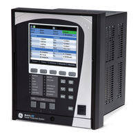
GE Multilin 850 Instruction Manual (664 pages)
Feeder Protection System
Brand:
GE
| Category:
Protection Device
| Size: 16 MB
Table of Contents
Table of Contents
3
Description of the 850 Feeder Protection System
13
Security Overview
19
850 Order Codes
21
Specifications
26
Device
26
Protection
26
Control
36
Monitoring
38
Recording
39
User-Programmable Elements
40
Metering
41
Inputs
43
Outputs
45
Power Supply
48
Communications
48
Testing & Certification
50
Physical
51
Environmental
51
Cautions and Warnings
52
Safety Words and Definitions
52
General Cautions and Warnings
52
Must-Read Information
54
Storage
55
For Further Assistance
56
Repairs
56
Product Identification
57
INSTALLATION Mechanical Installation
57
Dimensions
58
Mounting
59
Standard Panel Mount
60
Depth Reducing Collar
61
Draw-Out Unit Withdrawal and Insertion
63
Removable Power Supply
64
Removable Magnetic Module
65
Remote Module I/O (RMIO)
66
IP20 Back Cover
68
Arc Flash Sensor
69
Sensor Fiber Handling & Storage
69
Sensor Installation
70
Electrical Installation
70
Typical Wiring Diagram
70
Terminal Identification
74
Wire Size
81
RMIO Module Installation
82
Phase Sequence and Transformer Polarity
83
Ground CT Inputs
84
Voltage Inputs
86
Restricted Ground Fault Inputs
86
Zero-Sequence CT Installation
87
Control Power
88
Contact Inputs
89
Output Relays
90
Serial Communications
93
Irig-B
94
3 INTERFACES Front Control Panel Interface
97
Graphical Display
98
Working with Graphical Display
100
Single Line Diagram
103
Rugged and Membrane (3 PB) Front Panel Leds
105
Ten (10) Pushbutton Membrane Front Panel Leds
107
Home Screen Icons
109
Relay Messages
111
Target Messages
111
Self-Test Errors
111
Out of Service
115
Flash Messages
115
Label Removal
115
Software Interface
117
Enervista 8 Series Setup Software
117
Hardware & Software Requirements
117
Installing the Enervista 8 Series Setup Software
118
Upgrading the Software
120
Connecting Enervista 8 Series Setup Software to the Relay
121
Using the Quick Connect Feature
121
Configuring Ethernet Communications
122
Connecting to the Relay
124
Working with Setpoints & Setpoints Files
125
Engaging a Device
125
Entering Setpoints
125
File Support
126
Using Setpoints Files
127
Downloading & Saving Setpoints Files
127
Adding Setpoints Files to the Environment
128
Creating a New Setpoints File
129
Upgrading Setpoints Files to a New Revision
130
Printing Setpoints
131
Printing Values from a Connected Device
132
Loading Setpoints from a File
132
Uninstalling Files and Clearing Data
133
Quick Setup
133
Upgrading Relay Firmware
136
Loading New Relay Firmware
136
Advanced Enervista 8 Series Setup Software Features
140
SLD Configurator
140
Flexcurve Editor
147
Transient Recorder (Waveform Capture)
148
Protection Summary
152
Offline Settings File Conversion
154
Conversion Summary Report
155
Results Window
156
4 About Setpoints
157
Common Setpoints
159
Logic Diagrams
161
Setpoints Text Abbreviations
162
5 Device, System, Input and Output Setpoints
163
Clock
166
Real-Time Clock
166
PTP Configuration
167
Clock
169
Irig-B
169
SNTP Protocol
170
Security
170
Basic Security
172
Cybersentry
174
Communications
181
Modbus Protocol
181
Rs485
183
Wifi
183
Wifi Quick Start Procedure
185
Usb
186
Ethernet Ports
186
Network Settings Menu
187
Routing
188
DNP Protocol
191
DNP / IEC104 Point Lists
192
Iec 60870-5-104
195
Iec 60870-5-103
197
Iec 61850
197
The IEC 61850 Configurator
197
IEC 61850 Configurator Details
199
Remote Modbus Device
200
Transient Recorder
201
Data Logger
202
Fault Reports
205
Event Data
207
Flex States
208
Front Panel
208
Programmable Leds
208
Programmable Pushbuttons
211
Ten (10) Pushbutton Membrane Front Panel Defaults
216
Annunciator
217
Tab Pushbuttons
220
Display Properties
223
Default Screens
224
Home Screens
224
Clear Records
225
Resetting
225
Installation
226
System
227
Current Sensing
227
Voltage Sensing
228
Traditional VT
228
LEA (Low Energy Analog)
230
Power System
231
Breakers
232
Switches
235
Flexcurves
238
Inputs
246
Contact Inputs
247
Virtual Inputs
250
Analog Inputs
252
Remote Inputs
256
Outputs
257
Output Relays
257
Output Relay 1 (F1) Trip
260
Output Relay 2 (F4) Programmed as Close
262
Auxiliary Output Relays
264
Critical Failure Relay #8
265
Virtual Outputs
266
Analog Outputs
267
Percent of Load-To-Trip
279
Phase Time Overcurrent Protection (51P)
279
Phase Instantaneous Overcurrent Protection (50P)
283
Phase Directional Overcurrent Protection (67P)
285
Neutral Time Overcurrent Protection (51N)
288
Neutral Instantaneous Overcurrent Protection (50N)
291
Neutral Directional Overcurrent Protection (67N)
294
Ground Time Overcurrent Protection (51G)
299
Ground Instantaneous Overcurrent Protection (50G)
302
Ground Directional Overcurrent Protection (67G)
304
Sensitive Ground Time Overcurrent Protection (51SG)
309
Sensitive Ground Instantaneous Overcurrent Protection (50SG)
312
Sensitive Ground Directional Overcurrent Protection (67SG)
315
Restricted Ground Fault (87G)
320
Switch on to Fault (SOTF)
325
Negative Sequence Time Overcurrent Protection (51_2)
328
Negative Sequence Instantaneous Overcurrent Protection (50_2)
331
Negative Sequence Directional Overcurrent Protection (67_2)
334
Broken Conductor
338
Load Encroachment
341
Undercurrent (37)
344
Thermal Overload (49)
347
Voltage Elements
351
Undervoltage Curves
351
Phase Undervoltage Protection (27P)
353
Timed Undervoltage Protection (27T)
356
UV Reactive Power (27Q)
365
Auxiliary Undervoltage (27X)
372
Phase Overvoltage Protection (59P)
374
Auxiliary Overvoltage Protection (59X)
377
Neutral Overvoltage Protection (59N)
380
Negative Sequence Overvoltage Protection (59_2)
383
Admittance
386
Neutral Admittance (21YN)
386
Power Elements
394
Directional Power (32)
395
Wattmetric Ground Fault (32N)
400
Frequency Elements
405
Underfrequency (81U)
406
Overfrequency (81O)
409
Frequency Rate of Change (81R)
412
Fast Underfrequency
416
7 Monitoring
421
Trip and Close Circuit Monitoring
422
Breaker Arcing Current
430
Breaker Health
433
Functions
437
Power Factor (55)
437
Demand
443
Current Demand
444
Real Power Demand
446
Reactive Power
448
Apparent Power Demand
450
Pulsed Outputs
452
Digital Counters
455
Harmonic Detection
458
Transient Ground Fault Detection
461
RTD Temperature
465
RTD Trouble
470
Loss of Communications
471
8 CONTROL Setpoint Group
475
Local Control Mode (Breakers and Switches)
476
Breaker Control (2)
485
Switch Control (9)
488
Pole Discordance (52)
491
Virtual Input Control
497
Trip Bus
498
Breaker Failure (50BF)
500
Setup
501
Initiate
504
Arc Flash Protection
506
Synchrocheck (25)
508
Manual Close Blocking
513
Cold Load Pickup
516
Undervoltage Restoration
520
Underfrequency Restoration
524
Bus Transfer
528
ATS Wiring Diagrams
547
Autoreclose
551
Setup
553
Initiate
559
Shot
560
Rate Supervision
562
Current Supervision
564
Zone Coordination
567
CT Supervision
570
VT Fuse Failure (VTFF)
577
9 Flexlogic and Other Setpoints
579
Non-Volatile Latches
593
Flexlogic Equation
594
Viewing Flexlogic Graphics
596
Flexelements
596
Testing
603
Simulation
604
Setup
604
Pre-Fault
605
Fault
606
Post-Fault
607
Test Leds
608
Contact Inputs
608
Output Relays
608
Configurable SLD
610
Annunciator
610
STATUS Summary
610
Tab Pushbuttons
611
Breakers
612
Information
613
Main CPU
613
Comms CPU
613
Hardware Versions
614
Environment
614
Settings Audit
615
Switches
615
Last Trip Data
615
Arc Flash
616
Contact Inputs
616
Output Relays
616
Output Relay 1 (TRIP)
616
Output Relay 2 (CLOSE)
616
Virtual Inputs
617
Virtual Outputs
617
Flex State
618
Communications
618
GOOSE Rx and Tx
618
Device Status
622
Clock Status
623
PTP Status
623
Autoreclose
624
11 METERING Summary
628
Admittance
629
Neutral Admittance
629
Currents
629
Voltages
631
Frequency
632
Fast Underfrequency
633
Harmonics 1(Harmonics 2)
633
Harmonic Detection
634
Synchrocheck
634
Power
635
Energy
637
Power Factor
637
Current Demand
638
Power Demand
638
Thermal Capacity
639
Directional Power
639
Wattmetric Ground Fault
639
Transient Ground Fault Detection
640
CT Supervision (CTS)
640
Rtds
641
Rrtds
641
Arc Flash
641
RTD Maximums
642
RRTD Maximums
642
Analog Inputs
642
Flexelements
643
Events
645
Transient Records
646
Data Logger
646
Fault Reports
646
Breakers Records
648
Breaker Arcing Current
648
Breaker Health
648
Digital Counters
649
Remote Modbus Device
650
Clear Records
652
13 MAINTENANCE Environmental Health Report
655
General Maintenance
656
In-Service Maintenance
656
Out-Of-Service Maintenance
656
Unscheduled Maintenance (System Interruption)
656
Warranty
657
A.APPENDIX a Warranty
658
Revision History
658
Major Updates
658
Advertisement
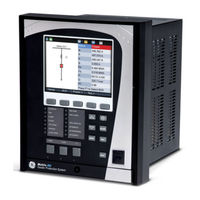
GE Multilin 850 Instruction Manual (616 pages)
Feeder Protection System
Brand:
GE
| Category:
Protection Device
| Size: 15 MB
Table of Contents
Table of Contents
3
INTRODUCTION Overview
11
Description of the 850 Feeder Protection System
12
Security Overview
17
850 Order Codes
18
Specifications
21
Device
21
Protection
21
Control
31
Monitoring
33
Recording
34
User-Programmable Elements
35
Metering
36
Inputs
38
Outputs
39
Power Supply
41
Communications
41
Testing & Certification
42
Physical
43
Environmental
43
Cautions and Warnings
44
Safety Words and Definitions
44
General Cautions and Warnings
44
Must-Read Information
47
Storage
48
For Further Assistance
48
Repairs
48
Product Identification
49
INSTALLATION Mechanical Installation
49
Dimensions
50
Mounting
51
Standard Panel Mount
52
Depth Reducing Collar
53
Draw-Out Unit Withdrawal and Insertion
55
Removable Power Supply
56
Removable Magnetic Module
57
Arc Flash Sensor
58
Sensor Fiber Handling & Storage
58
Sensor Installation
58
Electrical Installation
59
Typical Wiring Diagram
59
Terminal Identification
61
Wire Size
65
Phase Sequence and Transformer Polarity
66
Ground CT Inputs
66
Voltage Inputs
68
Restricted Earth Fault Inputs
68
Zero-Sequence CT Installation
69
Control Power
70
Contact Inputs
70
Output Relays
71
Serial Communications
74
Irig-B
75
3 INTERFACES Front Control Panel Interface
79
Graphical Display
79
Working with Graphical Display
81
Single Line Diagram
83
Rugged and Membrane Front Panel Leds
84
Home Screen Icons
86
Relay Messages
87
Target Messages
87
Self-Test Errors
88
Out of Service
91
Flash Messages
91
Label Removal
91
Software Interface
93
Enervista 8 Series Setup Software
93
Hardware & Software Requirements
93
Installing the Enervista 8 Series Setup Software
94
Upgrading the Software
96
Connecting Enervista 8 Series Setup Software to the Relay
97
Using the Quick Connect Feature
97
Configuring Ethernet Communications
99
Connecting to the Relay
100
Working with Setpoints & Setpoints Files
101
Engaging a Device
101
Entering Setpoints
101
File Support
102
Adding Setpoints Files to the Environment
103
Downloading & Saving Setpoints Files
103
Using Setpoints Files
103
Creating a New Setpoints File
105
Upgrading Setpoints Files to a New Revision
106
Printing Setpoints
107
Loading Setpoints from a File
108
Printing Values from a Connected Device
108
Uninstalling Files and Clearing Data
109
Quick Setup
109
Upgrading Relay Firmware
111
Loading New Relay Firmware
112
Advanced Enervista 8 Series Setup Software Features
115
SLD Configurator
115
Flexcurve Editor
122
Transient Recorder (Waveform Capture)
123
Protection Summary
127
Offline Settings File Conversion
129
Conversion Summary Report
130
Results Window
130
4 SETPOINTS Setpoints Main Menu
133
Setpoints Entry Methods
134
Common Setpoints
135
Logic Diagrams
136
Setpoints Text Abbreviations
137
Device
138
Custom Configuration
138
Real-Time Clock
138
Clock
141
PTP Configuration
141
Clock
143
SNTP Protocol
144
Security
145
Basic Security
146
Cybersentry
147
Communications
155
Wifi
155
Usb
158
Ethernet Ports
159
Modbus Protocol
161
Routing
165
DNP Protocol
168
DNP / IEC104 Point Lists
170
Iec 60870-5-104
173
Iec 60870-5-103
174
Iec 61850
175
Remote Modbus Device
177
Transient Recorder
178
Data Logger
180
Fault Reports
183
Event Data
185
Flex States
186
Front Panel
186
Programmable Leds
186
Programmable Pushbuttons
188
Tab Pushbuttons
193
Annunciator
196
Display Properties
199
Default Screens
200
Home Screens
200
Resetting
201
Installation
202
System
203
Current Sensing
203
Voltage Sensing
204
Traditional VT
204
Power System
205
Breakers
206
Switches
208
Flexcurves
211
Inputs
219
Contact Inputs
219
Virtual Inputs
222
Analog Inputs
224
Remote Inputs
228
Outputs
229
Output Relays
229
Output Relay 1 (F1) Trip
232
Output Relay 2 (F4) Programmed as Close
234
Auxiliary Output Relays
236
Critical Failure Relay #8
237
Virtual Outputs
238
Protection
240
Feeder Elements
242
Current Elements
245
Inverse Time Overcurrent Curves
246
Percent of Load-To-Trip
253
Phase Instantaneous Overcurrent Protection (50P)
256
Phase Directional Overcurrent Protection (67P)
258
Neutral Time Overcurrent Protection (51N)
261
Neutral Instantaneous Overcurrent Protection (50N)
264
Neutral Directional Overcurrent Protection (67N)
267
Ground Time Overcurrent Protection (51G)
272
Ground Instantaneous Overcurrent Protection (50G)
274
Ground Directional Overcurrent Protection (67G)
276
Sensitive Ground Time Overcurrent Protection (51SG)
281
Sensitive Ground Instantaneous Overcurrent Protection (50SG)
284
Sensitive Ground Directional Overcurrent Protection (67SG)
286
Restricted Ground (Earth) Fault (87G)
291
Switch on to Fault (SOTF)
296
Negative Sequence Time Overcurrent Protection (51_2)
299
Negative Sequence Instantaneous Overcurrent Protection (50_2)
301
Negative Sequence Directional Overcurrent Protection (67_2)
304
Broken Conductor
308
Load Encroachment
310
Thermal Overload (49)
314
Voltage Elements
317
Phase Undervoltage Protection (27P)
319
Timed Undervoltage Protection (27T)
322
UV Reactive Power (27Q)
332
Auxiliary Undervoltage (27X)
339
Phase Overvoltage Protection (59P)
342
Auxiliary Overvoltage Protection (59X)
345
Neutral Overvoltage Protection (59N)
348
Negative Sequence Overvoltage Protection (59_2)
351
Admittance
353
Power Elements
360
Wattmetric Ground Fault (32N)
366
Frequency Elements
371
Overfrequency (81O)
374
Frequency Rate of Change (81R)
377
Fast Underfrequency
381
Monitoring
385
Breaker Arcing Current
393
Breaker Health
396
Functions
400
Demand
406
Pulsed Outputs
415
Digital Counters
418
Harmonic Detection
421
RTD Temperature
424
RTD Trouble
429
Loss of Communications
430
Control
432
Local Control Mode (Breakers and Switches)
435
Breaker Control
444
Switch Control (9)
447
Pole Discordance (52)
450
Virtual Input Control
456
Trip Bus
457
Breaker Failure (50BF)
459
Setup
460
Initiate
462
Arc Flash Protection
464
Synchrocheck (25)
466
Manual Close Blocking
471
Cold Load Pickup
474
Undervoltage Restoration
478
Underfrequency Restoration
482
Bus Transfer
486
ATS Wiring Diagrams
505
Autoreclose
509
Setup
511
Initiate
517
Shot
518
Rate Supervision
519
Current Supervision
522
Zone Coordination
524
CT Supervision
526
VT Fuse Failure (VTFF)
533
Flexlogic
535
Timers
546
Flexlogic Equation
548
Viewing Flexlogic Graphics
550
Testing
557
Setup
558
Pre-Fault
559
Post-Fault
560
Contact Inputs
561
STATUS Summary
564
Tab Pushbuttons
565
Breakers
566
Last Trip Data
567
Contact Inputs
568
Virtual Inputs
569
Virtual Outputs
570
Information
575
Environment
576
Device Status
577
Clock
578
Autoreclose
579
METERING Summary
584
Admittance
585
Voltages
587
Frequency
588
Fast Underfrequency
589
Harmonic Detection
590
Power
591
Energy
592
Power Factor
593
Power Demand
594
Directional Power
595
Arc Flash
596
RTD Maximums
597
RECORDS Events
599
Fault Reports
600
Data Logger
601
Breakers
602
Remote Modbus Device
603
Clear Records
605
Environmental Health Report
607
General Maintenance
609
Warranty
611
A.APPENDIX a Warranty
612
Major Updates
612
Advertisement
Related Products
GE 869
GE 845
GE Multilin 889
GE Multilin W650
GE Multilin g60
GE Multilin 3 Series
GE Multilin MIGII
GE Multilin UR Series
GE Multilin D30
GE 8566267
GE Categories
Refrigerator
Ranges
Microwave Oven
Dishwasher
Air Conditioner
More GE Manuals
Login
Sign In
OR
Sign in with Facebook
Sign in with Google
Upload manual
Upload from disk
Upload from URL