
Related Manuals for GE 850


Summary of Contents for GE 850
- Page 1 Grid Solutions Feeder Protection System Feeder protection and control Instruction manual 850 version: 1.6x GE publication code: 1601-0298-A9 (GEK-119591H) *1601-0298-A9*...
- Page 2 The contents of this manual are the property of GE Multilin Inc. This documentation is furnished on license and may not be reproduced in whole or in part without the permission of GE Multilin. The content of this manual is for informational use only and is subject to change without notice.
-
Page 3: Table Of Contents
Table of Contents 1.INTRODUCTION Overview .............................. 1 - 1 Description of the 850 Feeder Protection System............1 - 2 Security Overview ..........................1 - 5 850 Order Codes..........................1 - 7 Specifications............................. 1 - 9 Protection..............................1 - 9 Control ................................. 1 - 18 Monitoring.............................. - Page 4 Real-time Clock............................4 - 6 PTP Configuration ............................. 4 - 7 Clock................................4 - 9 SNTP Protocol ............................4 - 10 Security ................................4 - 11 Basic Security............................4 - 13 CyberSentry ...............................4 - 16 Communications.............................4 - 23 850 FEEDER PROTECTION SYSTEM – INSTRUCTION MANUAL...
- Page 5 Ground Directional Overcurrent Protection ................4 - 151 Sensitive Ground Time Overcurrent Protection..............4 - 156 Sensitive Ground Instantaneous Overcurrent Protection..........4 - 159 Sensitive Ground Directional Overcurrent Protection ............4 - 161 850 FEEDER PROTECTION SYSTEM – INSTRUCTION MANUAL...
- Page 6 Cold Load Pickup..........................4 - 317 Undervoltage Restoration........................4 - 321 Underfrequency Restoration......................4 - 325 Bus Transfer............................4 - 329 ATS Wiring Diagrams ......................... 4 - 347 Autoreclose.............................4 - 351 Setup................................4 - 353 Initiate ............................... 4 - 360 850 FEEDER PROTECTION SYSTEM – INSTRUCTION MANUAL...
- Page 7 Frequency............................6 - 8 Fast Underfrequency........................6 - 9 Harmonics 1(Harmonics 2) ......................6 - 9 Harmonic Detection........................6 - 10 Synchrocheck ..........................6 - 11 Power..............................6 - 12 Energy..............................6 - 13 Power Factor............................6 - 14 850 FEEDER PROTECTION SYSTEM – INSTRUCTION MANUAL...
- Page 8 Breaker Health ............................7 - 5 Digital Counters..........................7 - 6 Clear Records .............................7 - 7 8.MAINTENANCE Environmental Health Report .....................8 - 1 A.APPENDIX A Warranty...............................A - 1 Revision history..........................A - 1 Major Updates............................A - 2 850 FEEDER PROTECTION SYSTEM – INSTRUCTION MANUAL...
-
Page 9: Introduction Overview
Chapter 1: Introduction Introduction The Mulitlin 850 relay is a microprocessor-based unit intended for the management and primary protection of distribution feeders, as well as for the management and backup protection of buses, transformers, and transmission lines. The 850 relay is particularly suited to overhead feeders, where automatic reclosing is normally applied. -
Page 10: Description Of The 850 Feeder Protection System
DESCRIPTION OF THE 850 FEEDER PROTECTION SYSTEM CHAPTER 1: INTRODUCTION Description of the 850 Feeder Protection System Relay functions are controlled by two processors: a Freescale MPC5125 32-bit microprocessor that measures all analog signals and digital inputs and controls all output relays, and a Freescale MPC8358 32-bit microprocessor that controls all the advanced Ethernet communication protocols. - Page 11 CHAPTER 1: INTRODUCTION DESCRIPTION OF THE 850 FEEDER PROTECTION SYSTEM Figure 1-1: Single Line Diagram Table 1-1: ANSI Device Numbers and Functions ANSI Device Description Synchrocheck 27P (2) Phase Undervoltage 27X (2) Auxiliary Undervoltage 32 (2) Directional Power Wattmetric Ground Fault (Wattmetric zero sequence directional)
- Page 12 DESCRIPTION OF THE 850 FEEDER PROTECTION SYSTEM CHAPTER 1: INTRODUCTION ANSI Device Description Auxiliary Overvoltage 59_2 Negative Sequence Overvoltage Ground Directional Element 67SG Sensitive Ground Directional Element Neutral Directional Element Phase Directional Element 67_2 Negative Sequence Directional Element Automatic Recloser...
-
Page 13: Security Overview
CHAPTER 1: INTRODUCTION SECURITY OVERVIEW Description User-programmable Pushbuttons Virtual Inputs (32) Virtual Outputs (32) Figure 1-2: Main Menu Hierarchy Security Overview The following security features are available: BASIC SECURITY 850 FEEDER PROTECTION SYSTEM – INSTRUCTION MANUAL 1–5... - Page 14 The basic security feature is present in the default offering of the 850 relay. The 850 introduces the notion of roles for different levels of authority. Roles are used as login names with associated passwords stored on the device. The following roles are available at present: Administrator, Operator, Factory and Observer, with a fixed permission structure for each one.
-
Page 15: 850 Order Codes
Each of these modules can be supplied in a number of configurations specified at the time NOTE of ordering. The information to specify an 850 relay is provided in the following Order Code figure: 850 FEEDER PROTECTION SYSTEM – INSTRUCTION MANUAL 1–7... - Page 16 850 ORDER CODES CHAPTER 1: INTRODUCTION Figure 1-3: 850 Order Codes 850 – E * NN 850 Feeder Protection System (Standard: English Language; Interface High Voltage PS, Graphical Control Panel) Language English Phase Currents 1A 3-phase current inputs (bank 1/2)
-
Page 17: Specifications
Curve Timing Accuracy:........Currents > 1.03 to 20 x pickup: ± 3% of operate time or ± ½ cycle (whichever is greater) from pickup to operate Voltage Restrained Function (51V):.....Modifies Pickup from 0.1 < V < 0.9 VT Nominal in a fixed linear relationship 850 FEEDER PROTECTION SYSTEM – INSTRUCTION MANUAL 1–9... - Page 18 <16 ms typical at 3 × Pickup at 60 Hz (Neutral IOC) <15 ms typical at 3 × Pickup at 50 Hz (Phase/Ground IOC) <20 ms typical at 3 × Pickup at 50 Hz (Neutral IOC) 1–10 850 FEEDER PROTECTION SYSTEM – INSTRUCTION MANUAL...
- Page 19 Current Sensitivity Threshold: .......0.05 x CT Characteristic Angle:.........0º to 359º in steps of 1° Angle Accuracy:...........± 2º Operation Time (FlexLogic™ operands): ..Reverse to Forward transition: < 12 ms, typically; Forward to Reverse transition: <8 ms, typically 850 FEEDER PROTECTION SYSTEM – INSTRUCTION MANUAL 1–11...
- Page 20 Dropout Level:............97 to 98% Operate Time (no direction transition): ..< 12 ms typical at 3 × Pickup at 60 Hz < 15 ms typical at 3 × Pickup at 50 Hz 1–12 850 FEEDER PROTECTION SYSTEM – INSTRUCTION MANUAL...
- Page 21 Operate Time:............<20 ms at 1.1 x pickup at 60 Hz <24 ms at 1.1 x pickup at 50 Hz Timing Accuracy: ..........± 3% of delay setting or ± ¼ cycle (whichever is greater) from pickup to operate 850 FEEDER PROTECTION SYSTEM – INSTRUCTION MANUAL 1–13...
- Page 22 Level Accuracy:............ ±0.5% of reading from 10 to 208 V Phases Required for Operation:....Any one, Any two, All three Undervoltage Curves:........Definite Time, GE IAV Inverse Time or FlexCurves A/B/C/D Pickup Time Delay:..........0.000 to 6000.000 s in steps of 0.001s Operate Time: ............
- Page 23 Operate Time:............< 55 ms at 1.1 x pickup at 60 Hz < 65 ms at 1.1 x pickup at 50 Hz Timer Accuracy:...........± 3% of delay setting or ± ¼ cycle (whichever is greater) from pickup to operate 850 FEEDER PROTECTION SYSTEM – INSTRUCTION MANUAL 1–15...
- Page 24 7 cycles at 0.3 Hz/s change typically 6.5 cycles at 0.5 Hz/s change Typical times are average Operate Times including variables such as frequency change FASTPATH: instance, test method, etc., and may vary by ± 0.5 cycles. 1–16 850 FEEDER PROTECTION SYSTEM – INSTRUCTION MANUAL...
- Page 25 Pickup Level:............-30.000 to 30.000 pu in steps of 0.001 pu Hysteresis:..............0.1 to 50.0% in steps of 0.1% Delta dt: ..............40 msec to 45 days Pickup and dropout delays: ......0.000 to 6000.000 s in steps of 0.001 s 850 FEEDER PROTECTION SYSTEM – INSTRUCTION MANUAL 1–17...
-
Page 26: Control
Dead Source Function:........None, LB & DL, DB & LL, DB & DL, DB OR DL, DB XOR DL Dead/Live Levels for Bus and Line: .... 0.00 to 1.50 x VT in steps of 0.01 x VT 1–18 850 FEEDER PROTECTION SYSTEM – INSTRUCTION MANUAL... -
Page 27: Monitoring
Minimum Operating Voltage: ......0.00 to 1.25 x VT in steps of 0.01 x VT Level Accuracy:............± 0.02 Timer Accuracy:...........± 3% of delay setting or ± 1¼ cycle (whichever is greater) from pickup to operate 850 FEEDER PROTECTION SYSTEM – INSTRUCTION MANUAL 1–19... - Page 28 Timer Accuracy: ..........Harmonics: ±3% of delay setting or ±1/4 cycle (whichever is greater) from pickup to operate THD: ±3% of delay setting or ±3 cycles (whichever is greater) from pickup to operate 1–20 850 FEEDER PROTECTION SYSTEM – INSTRUCTION MANUAL...
-
Page 29: Recording
Number of Records:...........1 Data Storage:............Non-volatile memory Time-tag Accuracy: ...........One microsecond Actuals: ..............Event Number of Last Trip, Timestamp of Last Trip, Cause of Last Trip, 64 Configurable FlexAnalog values Commands: ............Clear Last Trip Data 850 FEEDER PROTECTION SYSTEM – INSTRUCTION MANUAL 1–21... -
Page 30: User-Programmable Elements
Auto-reset timer:..........0.2 to 600.0 s in steps of 0.1 Hold timer: ............. 0.0 to 10.0 s in steps of 0.1 Timer accuracy: ..........±3% of delay setting or ±¼ cycle (whichever is greater) from pickup to operate 1–22 850 FEEDER PROTECTION SYSTEM – INSTRUCTION MANUAL... -
Page 31: Metering
Magnitude Accuracy: ........± 0.5% of reading or ± 0.2% of rated (whichever is greater) from 0.1 to 2.0 x CT ± 1.0% of reading > 2.0 x CT Angle Accuracy:...........2° (3° for 25 Hz) 850 FEEDER PROTECTION SYSTEM – INSTRUCTION MANUAL 1–23... - Page 32 5, 10, 15, 20, 30 minutes Current Pickup Level: ........10 to 10000 in steps of 1 A Dropout Level:............96-98% of Pickup level Level Accuracy:............ ± 2% NOTE: Factory tested at 25°C NOTE 1–24 850 FEEDER PROTECTION SYSTEM – INSTRUCTION MANUAL...
-
Page 33: Inputs
Wet Contacts: ............300 V DC maximum Selectable thresholds: ........17, 33, 84, 166 VDC Tolerance:...............±20% Recognition time: ..........1 ms (typical) Debounce time: ...........0.0 to 16.0 ms in steps of 0.5 ms Continuous current draw (burden): ....2 mA 850 FEEDER PROTECTION SYSTEM – INSTRUCTION MANUAL 1–25... - Page 34 Type: ................. Resistance (ohms) Range:..............0 to 500 Ω or 0.5 to 5.1 kΩ Bias current:............1.9 mA through the full range Accuracy:..............± 1% (of full scale based on input range) 1–26 850 FEEDER PROTECTION SYSTEM – INSTRUCTION MANUAL...
-
Page 35: Outputs
Operation Mode:..........Self-Reset, Latched, Pulsed, Non-Failsafe, Failsafe FORM-A VOLTAGE MONITOR Applicable voltage:..........20 to 250 VDC Trickle current:............1 to 2.5 mA Timer acurracy: ...........± 3% of operate time or ± 1/4 cycle (whichever is greater) 850 FEEDER PROTECTION SYSTEM – INSTRUCTION MANUAL 1–27... -
Page 36: Power Supply
Nominal DC Voltage:......... 24 V to 48 V Minimum DC Voltage:........20 V Maximum DC Voltage:........60 V POWER CONSUMPTION Typical:..............20 W / 40 VA Maximum: .............. 34 W / 70 VA 1–28 850 FEEDER PROTECTION SYSTEM – INSTRUCTION MANUAL... -
Page 37: Communications
Response time:.............10 ms typical Parity:................None, Odd, Even Protocol: ..............Modbus RTU, DNP 3.0, IEC 60870-5-103 Maximum distance: ...........1200 m (4000 feet) Isolation:..............2 kV WIFI Standard specification:........IEEE802.11bgn Range: ..............30 ft (direct line of sight) 850 FEEDER PROTECTION SYSTEM – INSTRUCTION MANUAL 1–29... -
Page 38: Testing & Certification
Ingress Protection IEC60529 IP54 front Environmental (Cold) IEC60068-2-1 -40C 16 hrs Environmental (Dry heat) IEC60068-2-2 85C 16hrs Relative Humidity Cyclic IEC60068-2-30 6 day humidity variant 2 IEEE/ANSI C37.90.1 4kV, 5 kHz 1–30 850 FEEDER PROTECTION SYSTEM – INSTRUCTION MANUAL... -
Page 39: Physical
-40C to 60C Humidity: Operating up to 95% (non condensing) @ 55C (As per IEC60068-2-30 Variant 2, 6 days) Altitude: 2000m (max) Pollution Degree: Overvoltage Category: Ingress Protection: IP54 Front Insulation Class: 850 FEEDER PROTECTION SYSTEM – INSTRUCTION MANUAL 1–31... -
Page 40: Cautions And Warnings
Follow the requirements of this manual, including adequate wiring size and type, terminal torque settings, voltage, current magnitudes applied, and adequate isolation/ clearance in external wiring from high to low voltage circuits. Use the device only for its intended purpose and application. 1–32 850 FEEDER PROTECTION SYSTEM – INSTRUCTION MANUAL... - Page 41 Use an external disconnect to isolate the mains voltage supply. 850 FEEDER PROTECTION SYSTEM – INSTRUCTION MANUAL 1–33...
- Page 42 This product is rated to Class A emissions levels and is to be used in Utility, Substation FASTPATH: Industrial environments. Not to be used near electronic devices rated for Class B levels. 1–34 850 FEEDER PROTECTION SYSTEM – INSTRUCTION MANUAL...
-
Page 43: Must-Read Information
Note that the factory role password may not be changed. • In 850 both DNP and IEC104 protocol can work at the same time, but the user has to consider that there is only one point map. So, both protocols use the same configured points. -
Page 44: For Further Assistance
Worldwide telephone: +1 905 927 7070 Europe/Middle East/Africa telephone: +34 94 485 88 54 North America toll-free: 1 800 547 8629 Fax: +1 905 927 5098 Worldwide e-mail: multilin.tech@ge.com Europe e-mail: multilin.tech.euro@ge.com Website: http://www.gegridsolutions.com/multilin/ 1–36 850 FEEDER PROTECTION SYSTEM – INSTRUCTION MANUAL... -
Page 45: Product Identification
This section describes the mechanical installation of the system, including dimensions for mounting and information on module withdrawal and insertion. Product Identification The product identification label is located on the side panel of the 850. This label indicates the product model, serial number, and date of manufacture. Figure 2-1: Product Label 850 FEEDER PROTECTION SYSTEM –... -
Page 46: Dimensions
MECHANICAL INSTALLATION CHAPTER 2: INSTALLATION Dimensions The dimensions (in inches [millimeters]) of the 850 are shown below. Additional dimensions for mounting, and panel cutouts, are shown in the following sections. Figure 2-2: 850 Dimensions Mounting The unit can be mounted two ways: standard panel mount or optional tab mounting, if required. -
Page 47: Standard Panel Mount
The standard panel mount and cutout dimensions are illustrated below. To avoid the potential for personal injury due to fire hazards, ensure the unit is CAUTION: mounted in a safe location and/or within an appropriate enclosure. Figure 2-4: Standard panel mount 850 FEEDER PROTECTION SYSTEM – INSTRUCTION MANUAL 2–3... -
Page 48: Draw-Out Unit Withdrawal And Insertion
Turn off control power before drawing out or re-inserting the relay to prevent mal- FASTPATH: operation. Follow the steps outlined in the diagrams below to insert and withdraw the Draw-out unit. 2–4 850 FEEDER PROTECTION SYSTEM – INSTRUCTION MANUAL... -
Page 49: Removable Power Supply
Figure 2-6: Unit withdrawal and insertion diagram Removable Power Supply Follow the steps outlined in the Insert or Remove Power Supply diagram to insert (#1) or remove (#2) the power supply from the unit. 850 FEEDER PROTECTION SYSTEM – INSTRUCTION MANUAL 2–5... - Page 50 MECHANICAL INSTALLATION CHAPTER 2: INSTALLATION Figure 2-7: Insert or Remove the Power Supply Figure 2-8: Unlatch Module (location is marked by arrow) 2–6 850 FEEDER PROTECTION SYSTEM – INSTRUCTION MANUAL...
-
Page 51: Removable Magnetic Module
CHAPTER 2: INSTALLATION MECHANICAL INSTALLATION Removable Magnetic Module Follow the steps outlined in the diagram below to insert or remove the magnetic module from the unit. Figure 2-9: Insert or Remove the Magnetic Module 850 FEEDER PROTECTION SYSTEM – INSTRUCTION MANUAL 2–7... -
Page 52: Arc Flash Sensor
In the event of this assertion, the Hazard Reduction Category code cannot be maintained unless backup protection is continuing to maintain it. Electrical Installation Typical Wiring Diagram The following illustrates the electrical wiring of the Draw-out unit. 2–8 850 FEEDER PROTECTION SYSTEM – INSTRUCTION MANUAL... - Page 53 CHAPTER 2: INSTALLATION ELECTRICAL INSTALLATION Figure 2-11: Typical wiring diagram – Draw-out unit 850 FEEDER PROTECTION SYSTEM – INSTRUCTION MANUAL 2–9...
-
Page 54: Terminal Identification
This is to ensure the adjacent lower terminal block does not interfere with the lug body. Figure 2-12: Orient the Lugs Correctly SCREW WASHER LOWER TERMI AL TERMI AL BLOCK DIVIDER Figure 2-13: Correct Installation Method 2–10 850 FEEDER PROTECTION SYSTEM – INSTRUCTION MANUAL... - Page 55 ELECTRICAL INSTALLATION Figure 2-14: INCORRECT INSTALLATION METHOD (lower lug reversed) A broad range of applications are available for the 850 relays. As such, it is not possible to present typical connections for all possible schemes. The information in this section covers the important aspects of interconnections, in the general areas of instrument transformer inputs, other inputs, outputs, communications and grounding.
- Page 56 Table 2-1: Power Supply H - HV Power Supply Terminal Description Line Neutral Ground Table 2-2: Power Supply L - LV Power Supply Terminal Description (DC Voltage input polarity) +ve (positive) -ve (negative) Ground 2–12 850 FEEDER PROTECTION SYSTEM – INSTRUCTION MANUAL...
- Page 57 CONTACT IN_2 CONTACT IN_3 CONTACT IN_4 CONTACT IN_5 CONTACT IN_6 CONTACT IN_7 CONTACT IN COM DC +24 FC_3 NC Critical Fail Relay FC_3 COM Critical Fail Relay FC_3 NO Critical Fail Relay 850 FEEDER PROTECTION SYSTEM – INSTRUCTION MANUAL 2–13...
-
Page 58: Wire Size
Suggested wiring screw tightening torques are: terminal strips A-H tighten to 4.5 in-lbs (0.5 N-m) and terminal blocks J, K to 15 in-lb (1.7 N-m). Figure 2-16: Fiber Connector Types (S - ST) 2–14 850 FEEDER PROTECTION SYSTEM – INSTRUCTION MANUAL... -
Page 59: Phase Sequence And Transformer Polarity
The phase sequence is user programmable for either ABC or ACB rotation. The 850 relay has four (4) current inputs in each J slot and K slot. Three of them are used for connecting to the phase CT phases A, B, and C. The fourth input is a ground input that can be connected to either a ground CT placed on the neutral from a Wye connected transformer winding, or to a “donut”... - Page 60 ELECTRICAL INSTALLATION CHAPTER 2: INSTALLATION Figure 2-17: Ground Inputs Figure 2-18: Sensitive Ground Inputs 2–16 850 FEEDER PROTECTION SYSTEM – INSTRUCTION MANUAL...
-
Page 61: Voltage Inputs
ELECTRICAL INSTALLATION Voltage Inputs The 850 relays have four channels for AC voltage inputs, each with an isolating transformer. Voltage transformers up to a maximum 5000:1 ratio may be used. The nominal secondary voltage must be in the 10 to 240 V range. In Main-Tie-Main bus transfer scheme, the three phase inputs are mostly used for “Bus voltage”. -
Page 62: Zero-Sequence Ct Installation
UNSHIELDED CABLE SHIELDED CABLE Ground connection to neutral Stress cone must be on the source side Source Source shields Ground outside CT To ground; LOAD must be on load side 996630A5 LOAD 2–18 850 FEEDER PROTECTION SYSTEM – INSTRUCTION MANUAL... -
Page 63: Control Power
Wet or Dry input signal types can be connected to contact input terminals as shown in the figure: Wet and Dry Contact Input Wiring Examples. Dry inputs use an internal +24V that is supplied by the 850. The voltage threshold must be set to 17V for the inputs to be recognized using the internal +24V. - Page 64 ELECTRICAL INSTALLATION CHAPTER 2: INSTALLATION INPUT SIGNAL SWITCH (WET) INPUT SIGNAL SWITCH (DRY) EXTERNAL DC POWER SUPPLY 2–20 850 FEEDER PROTECTION SYSTEM – INSTRUCTION MANUAL...
-
Page 65: Output Relays
AUX 11 RELAY_3 AUX 3 RELAY_11 AUX 11 RELAY_4 AUX 4 RELAY_12 AUX 12 RELAY_4 AUX 4 RELAY_12 AUX 12 RELAY_4 AUX 4 RELAY_12 AUX 12 RELAY_5 Digital In_1 RELAY_13 Digital In_8 850 FEEDER PROTECTION SYSTEM – INSTRUCTION MANUAL 2–21... - Page 66 RELAY_12 Digital In_3 RELAY_10 Analog Out_4 RELAY_13 Digital In_4 RELAY_10 Analog Out_5 RELAY_13 Return RELAY_10 Analog Out_6 RELAY_13 Shield RELAY_11 Analog Out_7 RELAY_14 Reserved RELAY_11 Return RELAY_14 Reserved RELAY_11 Shield RELAY_14 Reserved 2–22 850 FEEDER PROTECTION SYSTEM – INSTRUCTION MANUAL...
-
Page 67: Serial Communications
CAUTION: that the common terminals of each RS485 port are tied together and grounded only once, at the master or at the 850. Failure to do so may result in intermittent or failed communications. The source computer/PLC/SCADA system should have similar transient protection devices installed, either internally or externally. -
Page 68: Irig-B
DC level shift or amplitude modulated (AM) form. The type of form is auto-detected by the 850 relay. Third party equipment is available for generating the IRIG-B signal; this equipment may use a GPS satellite system to obtain the time reference so that devices at different geographic locations can also be synchronized. - Page 69 • Interfacing via the EnerVista 8 Series Setup software. This section provides an overview of the interfacing methods available with the 850 using the relay control panel and EnerVista 8 Series Setup software. For additional details on interface parameters (for example, settings, actual values, etc.), refer to the individual chapters.
- Page 70 Pressing the Menu key during the display of the default message, returns the display to the last message shown before the default message appeared. Any Trip, Alarm, or Pickup is displayed immediately, automatically overriding the default message. 3–2 850 FEEDER PROTECTION SYSTEM – INSTRUCTION MANUAL...
-
Page 71: Interfaces Front Control Panel Interface
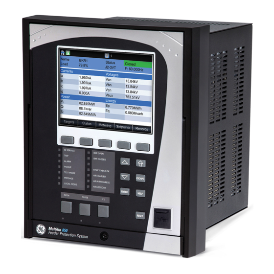
CHAPTER 3: INTERFACES FRONT CONTROL PANEL INTERFACE Figure 3-2: 850 Display Page Hierarchy 850 FEEDER PROTECTION SYSTEM – INSTRUCTION MANUAL 3–3... -
Page 72: Graphical Display
Pages Figure 3-3: Typical paging operation from the Main Menu There are two ways to navigate throughout the 850 menu: using the pushbuttons corresponding to the soft tabs from the screen, or by selecting the item from the list of items on the screen using the “Up”... - Page 73 The Escape pushbutton is used to display the previous menu. This pushbutton can also be used to cancel a setpoint change. 850 FEEDER PROTECTION SYSTEM – INSTRUCTION MANUAL 3–5...
- Page 74 The Reset pushbutton clears all latched LED indications, target messages, and latched output relays, providing the conditions causing these events are not present. To change/view an item on from the 850 menus: Use the pushbuttons that correspond to the tabs (Targets, Status, Metering, Setpoints, Records) on the screen to select a menu.
-
Page 75: Single Line Diagram
BKR 1 Open operand. Figure 3-6: BKR1 Operand LED settings and screen symbols Single Line Diagram for 850 The 850 has a single line diagram (SLD) that represents the power system. The single line diagram provided is pre-configured to show: •... -
Page 76: Led Status Indicators
• Reset mode: self-reset or latched The 850 front panel provides two columns of 7 LED indicators each, and 3 LED pushbutton indicators. The “IN-SERVICE” (LED 1) and the “PICKUP” (LED 4) indicators from the first LED column are non-programmable LEDs. The bottom 3 LED indicators from the first column, and the 7 LED indicators from the second LED column are fully programmable. - Page 77 ON until the RESET button on the front panel is pressed after the operand is reset. Default labels are installed on every 850. A custom LED template is available for editing and printing, refer to publication GET-20035 from http://www.gegridsolutions.com/multilin.
-
Page 78: Home Screen Icons
Table 3-6: Breaker Health Icon Description The Breaker Health icon is blue when the setting for the breaker health function is not disabled. When the setting is disabled the icon is grey. 3–10 850 FEEDER PROTECTION SYSTEM – INSTRUCTION MANUAL... -
Page 79: Relay Messages
“CLEAR”, or by initiating a RESET command. The “CLEAR” command clears only the Target Messages, while initiating a RESET clears not only the Target Messages, but also any latched LEDs and output relays. 850 FEEDER PROTECTION SYSTEM – INSTRUCTION MANUAL 3–11... -
Page 80: Self-Test Errors
Displays “Major Self-test error” with the error code as a target message • Records the major self-test failure in the Event Recorder Under both conditions, the targets cannot be cleared if the error is still active. Figure 3-10: Minor Errors 3–12 850 FEEDER PROTECTION SYSTEM – INSTRUCTION MANUAL... - Page 81 CPU and LEDs, Keypad or peripheral memory devices Invalid MAC MAC address is not in Every 1 second Address the product range Calibration Error Unit has default Boot-up and Every 1 calibration values second 850 FEEDER PROTECTION SYSTEM – INSTRUCTION MANUAL 3–13...
- Page 82 1. – Failure is logged after the detection of 5 consecutive failures 2. $ – is the slot ID (i.e., F, G, H etc.) 3.To disable Link Error Primary target when not in-use with SE order code, change IP address to 127.0.0.1 3–14 850 FEEDER PROTECTION SYSTEM – INSTRUCTION MANUAL...
-
Page 83: Out Of Service
The factory default flash message time is 5 seconds. Label Removal The following procedure describes how to use the label removal tool. Bend the tabs of the tool upwards as shown in the image. 850 FEEDER PROTECTION SYSTEM – INSTRUCTION MANUAL 3–15... - Page 84 Slide the label tool under the user-programmable pushbutton label as shown in the next image. Make sure the bent tab is pointing away from the relay. Remove the tool and user-programmable pushbutton label as shown in image. 3–16 850 FEEDER PROTECTION SYSTEM – INSTRUCTION MANUAL...
-
Page 85: Software Interface
The EnerVista 8 Series Setup software can run without a 850 connected to the computer. In this case, settings may be saved to a file for future use. If a 850 is connected to a PC and communications are enabled, the 850 can be programmed from the setting screens. In addition, measured values, status and trip messages can be displayed with the actual value screens. - Page 86 USB driver is loaded into the computer, and the installation program automatically creates icons and adds the EnerVista 8 Series Setup software to the Windows start menu. The 850 device is added to the list of installed IEDs in the EnerVista Launchpad window, as shown below. 3–18...
- Page 87 If you are going to communicate from your computer to the 850 Relay using the USB port: 10. Plug the USB cable into the USB port on the 850 Relay then into the USB port on your computer. 11. Launch EnerVista 8 Series Setup software from LaunchPad.
-
Page 88: Connecting Enervista 8 Series Setup Software To The Relay
USB is selected in the interface drop-down list. Select “USB” and press the Connect button. Ethernet or WiFi can also be used as the interface for Quick Connect as shown next. 3–20 850 FEEDER PROTECTION SYSTEM – INSTRUCTION MANUAL... -
Page 89: Configuring Ethernet Communications
FASTPATH: Install and start the latest version of the EnerVista 8 Series Setup software (available from the GE EnerVista CD or Website). See the previous section for the installation procedure. Click on the Device Setup button to open the Device Setup window and click the Add Site button to define a new site. - Page 90 Enter the IP address, slave address, and Modbus port values assigned to the 850 relay (from the SETPOINTS > DEVICE > COMMUNICATIONS menu). Click the Read Order Code button to connect to the 850 and upload the order code. If a communications error occurs, ensure that the Ethernet communication values correspond to the relay setting values.
-
Page 91: Connecting To The Relay
The settings can now be edited, printed, or changed. Other setpoint and command windows can be displayed and edited in a similar manner. "Actual Values" windows are also available for display. These windows can be arranged, and resized, if desired. 850 FEEDER PROTECTION SYSTEM – INSTRUCTION MANUAL 3–23... -
Page 92: Working With Setpoints & Setpoints Files
Click = to exit from the keypad and keep the new value. Click on X to exit from the keypad and retain the old value. 3–24 850 FEEDER PROTECTION SYSTEM – INSTRUCTION MANUAL... -
Page 93: File Support
In the Setpoints > System Setup > Voltage Sensing dialog box, click on Save to save the values into the 850. Click YES to accept any changes and exit the window. Click Restore to retain previous values. Click Default to restore Default values. -
Page 94: Using Setpoints Files
Modbus user map Factory default values are supplied and can be restored after any changes. The 850 displays relay setpoints with the same hierarchy as the front panel display. Downloading & Saving Setpoints must be saved to a file on the local PC before performing any firmware Setpoints Files upgrades. -
Page 95: Adding Setpoints Files To The Environment
As for any other MS Windows® application, browse for the file to be added then click Open. The new file and complete path will be added to the file list. 850 FEEDER PROTECTION SYSTEM – INSTRUCTION MANUAL 3–27... -
Page 96: Creating A New Setpoints File
Select the file name and path to store the file, or select any displayed file name to replace an existing file. All 850 setpoint files should have the extension ‘.cid’ (for example, ‘850 1.cid’). Click OK to complete the process. Once this step is completed, the new file, with a complete path, is added to the 850 software environment. -
Page 97: Upgrading Setpoints Files To A New Revision
Upgrading Setpoints It is often necessary to upgrade the revision for a previously saved setpoint file after the Files to a New 850 firmware has been upgraded. This is illustrated in the following procedure: Revision Establish communications with the 850 relay. -
Page 98: Printing Values From A Connected Device
OK. Actual values lists can be printed in the same manner by right clicking on the desired device (in the device list) and selecting the Print Device Information option. 3–30 850 FEEDER PROTECTION SYSTEM – INSTRUCTION MANUAL... -
Page 99: Loading Setpoints From A File
The following procedure illustrates how to load setpoints from a file. Before loading a setpoints file, it must first be added to the 850 environment as described in the section, Adding Setpoints Files to the Environment. -
Page 100: Quick Setup
The Quick Setup item is accessed from the EnerVista software from different screens. Online and offline settings changes are made from the corresponding Quick Setup screen. Figure 3-12: 850 Quick Setup (Online) tree position Figure 3-13: 850 Quick Setup (Offline) tree position Quick Setup is designed to allow quick and easy user programming. - Page 101 • The user can configure and save the settings as required. • The Save, Restore and Default buttons function the same as in the individual setting setup screens. 850 FEEDER PROTECTION SYSTEM – INSTRUCTION MANUAL 3–33...
-
Page 102: Upgrading Relay Firmware
Note that uploading firmware to a relay having a Communications card must be done with “Port 4 operation” configured as independent. Before upgrading firmware, it is very important to save the current 850 settings to a file on FASTPATH: your PC. After the firmware has been upgraded, it will be necessary to load this file back into the 850. -
Page 103: Loading New Relay Firmware
The firmware filename has the following format. The following screen appears. Select YES to proceed. EnerVista 8 Series Setup software now prepares the 850 to receive the new firmware file. The 850 front panel momentarily displays “Upload Mode”, indicating that it is in upload mode. - Page 104 SOFTWARE INTERFACE CHAPTER 3: INTERFACES The following screen appears, click YES to proceed with the firmware loading process. 3–36 850 FEEDER PROTECTION SYSTEM – INSTRUCTION MANUAL...
- Page 105 Wait for the Comms upload process to complete. Wait for the Mains upload process to complete. The EnerVista 8 Series Setup software notifies the user when the 850 has finished loading and notifies the user to Cycle power to the relay to complete firmware update.
-
Page 106: Advanced Enervista 8 Series Setup Software Features
• The user can load Trip Times from a CSV File • The screen above shows the model followed by 850 for viewing FlexCurves. Select Initialize to copy the trip times from the selected curve to the FlexCurve. 3–38 850 FEEDER PROTECTION SYSTEM – INSTRUCTION MANUAL... -
Page 107: Transient Recorder (Waveform Capture)
"CFG." The other file is a "DAT" file, required by the COMTRADE file for proper display of waveforms. • To view a previously saved COMTRADE file, click the Open button and select the corresponding COMTRADE file. 850 FEEDER PROTECTION SYSTEM – INSTRUCTION MANUAL 3–39... - Page 108 • From the window main menu bar, press the Preference button to open the COMTRADE Setup page, in order to change the graph attributes. 3–40 850 FEEDER PROTECTION SYSTEM – INSTRUCTION MANUAL...
- Page 109 The Waveform Capture window reappears based on the selected graph attributes. To view a vector graph of the quantities contained in the waveform capture, press the View Phasors button to display the following window: 850 FEEDER PROTECTION SYSTEM – INSTRUCTION MANUAL 3–41...
-
Page 110: Protection Summary
With the software running and communications established, select the Setpoints > Protection Summary menu item to open the Protection Summary window. The Protection Summary screen is as follows: 3–42 850 FEEDER PROTECTION SYSTEM – INSTRUCTION MANUAL... - Page 111 CHAPTER 3: INTERFACES SOFTWARE INTERFACE 850 FEEDER PROTECTION SYSTEM – INSTRUCTION MANUAL 3–43...
-
Page 112: Offline Settings File Conversion
SR Series platform. The feature allows users, who have SR devices, to convert their existing 750 offline settings files to 8 Series files and write them to their 850 devices. The EnerVista 8 Series Setup software reduces the manual effort required when moving from an older product to the 850. -
Page 113: Conversion Summary Report
For future reference, the user is advised to take a printout of the conversion report CAUTION: immediately after the conversion. All conversion reports are removed and become inaccessible if the user removes or modifies the converted file from the 8 Series Setup Software. 850 FEEDER PROTECTION SYSTEM – INSTRUCTION MANUAL 3–45... -
Page 114: Results Window
EnerVista taskbar or it can be printed from the “GUI” print button. Although the report shows successful conversion (green checkbox), the settings must still NOTE: be verified before putting the relay in service. NOTE 3–46 850 FEEDER PROTECTION SYSTEM – INSTRUCTION MANUAL... -
Page 115: Setpoints Setpoints Main Menu
Setpoints Setpoints Main Menu The 850 has a considerable number of programmable setpoints, all of which make the relay extremely flexible. These setpoints have been grouped into a variety of menus as shown below. Each setpoints menu has sub-sections that describe in detail the setpoints found on that menu. -
Page 116: Setpoints Entry Methods
Files can be stored and downloaded for fast, error free entry when a computer is used. To facilitate this process, the GE EnerVista CD with the EnerVista 8 Series Setup software is supplied with the relay. The relay leaves the factory with setpoints programmed to default values, and it is these values that are shown in all the setpoint message illustrations. -
Page 117: Common Setpoints
The range is “Disabled”, “Forward”, and “Reverse”. If set to “Disabled”, the element is allowed to operate for current flow in any direction. There is no supervision from the directional 850 FEEDER PROTECTION SYSTEM – INSTRUCTION MANUAL 4–3... -
Page 118: Logic Diagrams
850 relay. The targets disappear from the screen when “Self-Reset” is selected, and the conditions are cleared. The targets stay on the screen, when “Latched” is selected, and the conditions are cleared. -
Page 119: Setpoints Text Abbreviations
Hz: Hertz • MAX: maximum • MIN: minimum • SEC, s: seconds • UV: undervoltage • OV: overvoltage • VT: voltage transformer • Ctrl: control • Hr & hr: hour • O/L: overload 850 FEEDER PROTECTION SYSTEM – INSTRUCTION MANUAL 4–5... -
Page 120: Device
PTP and IRIG-B can be swapped. If both PTP and IRIG-B are available to the 850, by default the 850 clock syncs to PTP over IRIG-B. If PTP is not available the 850 CPU syncs the internal clock to IRIG-B. -
Page 121: Ptp Configuration
A setting can be chosen that reduces worst-case error to half of the range between minimum and maximum uncompensated delay if these values are known. 850 FEEDER PROTECTION SYSTEM – INSTRUCTION MANUAL 4–7... - Page 122 7. Depending on the characteristics of the device to which the relay is directly linked, VLAN Priority may have no effect. The setting applies to all of the relay’s PTP-capable ports. 4–8 850 FEEDER PROTECTION SYSTEM – INSTRUCTION MANUAL...
-
Page 123: Clock
Range: January to December (all months) Default: Not Set DST START DAY Range: SUN to SAT (all days of the week) Default: Not Set DST START WEEK Range: 1st, 2nd, 3rd, 4th, Last Default: Not Set 850 FEEDER PROTECTION SYSTEM – INSTRUCTION MANUAL 4–9... -
Page 124: Sntp Protocol
Range: Standard IP Address Format Default: 0.0.0.0 SNTP UDP PORT NUMBER Range: 0 to 65535 in steps of 1 Default: 123 The SNTP and PTP settings take effect after rebooting the relay. FASTPATH: 4–10 850 FEEDER PROTECTION SYSTEM – INSTRUCTION MANUAL... -
Page 125: Security
- Non-alphabetic characters (for example, ~, !, @, #, $,%, &) PASSWORD RECOVERY PROCEDURE In the event of losing all passwords, the 850 can be reset to factory defaults by following the procedure below: The customer sends an email to the customer support department providing a valid serial number and using a recognizable corporate email account. - Page 126 Administrator may always be able to connect. This is because the maximum number of TCP connections from EnerVista, when the Communications card is not present, is only three. 4–12 850 FEEDER PROTECTION SYSTEM – INSTRUCTION MANUAL...
-
Page 127: Basic Security
If password complexity is enabled, the rules as defined in the Password Complexity section must be obeyed. If password complexity is disabled this setting accepts 1 to 20 alphanumeric characters. PATH: SEPTPOINTS > DEVICE > SECURITY > CHANGE LOCAL PASSWORDS 850 FEEDER PROTECTION SYSTEM – INSTRUCTION MANUAL 4–13... - Page 128 It can be either switched on or assigned to a digital input. If assigned to a digital input, the digital input needs to be activated through a physical key. 4–14 850 FEEDER PROTECTION SYSTEM – INSTRUCTION MANUAL...
- Page 129 If the maximum number of Observer roles already logged in on the relay has been reached, NOTE: you must log in on the Security screen within one minute of making the connection otherwise your session is terminated. NOTE 850 FEEDER PROTECTION SYSTEM – INSTRUCTION MANUAL 4–15...
-
Page 130: Cybersentry
Commands may be issued freely through protocols other than Modbus (e.g., DNP, IEC 104, FASTPATH: and, IEC 61850) without user authentication or encryption of data taking place, even if the relay has the advanced security feature enabled. 4–16 850 FEEDER PROTECTION SYSTEM – INSTRUCTION MANUAL... - Page 131 If the user enters the wrong password, the “Authentication Failed!” message is displayed. – If the maximum failed authentications occur, the “Account Blocked!” message is displayed. – The Observer user role is the default choice and it does not require a password. 850 FEEDER PROTECTION SYSTEM – INSTRUCTION MANUAL 4–17...
- Page 132 The Access timeout is the time of idleness before a logged in user is automatically logged out. This timeout setting applies to all users, independent of the communication channel (serial, Ethernet or direct access). 4–18 850 FEEDER PROTECTION SYSTEM – INSTRUCTION MANUAL...
- Page 133 – The default password is “0”. – The Observer does not have a password associated with it. So there is no need to show it in the list of password changing roles. 850 FEEDER PROTECTION SYSTEM – INSTRUCTION MANUAL 4–19...
- Page 134 For this reason, if these settings have been modified, offline, NOTE they will not be written during the file write operation. 4–20 850 FEEDER PROTECTION SYSTEM – INSTRUCTION MANUAL...
- Page 135 The following are settings that need to be configured through EnerVista, in order to set up communication with a Radius server on 850. For configuring the RADIUS server itself, consult the RADIUS documentation. An example is provided, see Communications Guide.
- Page 136 AUTHENTICATION FAIL Operand set for Failed Authentication self test and alarm UNAUTH SETTING CHANGE ATTEMPT Operand set for unauthorized setting change action RADIUS SRV UNAVAILABLE Operand set for RADIUS servers unavailable self test 4–22 850 FEEDER PROTECTION SYSTEM – INSTRUCTION MANUAL...
-
Page 137: Communications
Mode with Cipher Block Chaining Message Authentication Code Protocol), which provides an enhanced data cryptographic encapsulation mechanism based on AES (Advanced Encryption Standard). CCMP makes WPA2 much stronger and secure than its predecessors, WPA and WEP. 850 FEEDER PROTECTION SYSTEM – INSTRUCTION MANUAL 4–23... -
Page 138: Wifi
The setting specifies the address of the access point AP which the 8 Series device uses for communicating over WiFi. WiFi Security The setting enables WiFi security. If set to “None”, there is no security and all traffic is open. By default WiFi Security is set to WPA2-PSK. 4–24 850 FEEDER PROTECTION SYSTEM – INSTRUCTION MANUAL... - Page 139 WiFi Quick Start Procedure NOTE The following provides the settings information and instructions to quickly setup WiFi. Required Equipment • 8-Series Relay with WiFi functionality • PC with WiFi • Access Point 850 FEEDER PROTECTION SYSTEM – INSTRUCTION MANUAL 4–25...
-
Page 140: Usb
USB. Connecting multiple 8 Series relays over USB to a single PC is not possible because in the FASTPATH: case of USB, the IP address of the device 172.16.0.2 is constant. 4–26 850 FEEDER PROTECTION SYSTEM – INSTRUCTION MANUAL... -
Page 141: Ethernet Ports
IEEE 1588, SNTP, IEC 62439-3 clause 4 (PRP), TFTP, SFTP Network Settings Menu The following are the network settings menu of the 850 to accommodate the features of the 850 product. If the communications card is installed network port 1 is no longer available. -
Page 142: Modbus Protocol
Modbus is a single master / multiple slave type of protocol suitable for a multi-drop configuration. The 850 is always a Modbus slave with a valid slave address range 1 to 254. DATA FRAME FORMAT AND DATA RATE One data frame of an asynchronous transmission to or from an 850 typically consists of 1 start bit, 8 data bits, and 1 stop bit. - Page 143 Range: 1 to 254 in steps of 1 Default: 254 For the RS485 ports each 850 must have a unique address from 1 to 254. Address 0 is the broadcast address to which all Modbus slave devices listen. Addresses do not have to be sequential, but no two devices can have the same address, otherwise conflicts resulting in errors occur.
- Page 144 (“holding registers”). Holding registers are 16 bit (two byte) values transmitted high order byte first. As a result all 850 Setpoints are sent as two bytes. The maximum number of registers that can be read in one transmission is 125.
- Page 145 Modbus Implementation: Preset Single Register 850 Implementation: Store Single Setpoint The command allows the master to store a single setpoint into the memory of an 850. The slave response to this function code is to echo the entire master transmission.
- Page 146 SP Group 3 Active Bit 1 SP Group 2 Active Bit 2 Pickup State Bit 3 Breaker Connected Bit 4 Breaker Closed Bit 5 Breaker Tripped Bit 6 Alarm Bit 7 Trip 4–32 850 FEEDER PROTECTION SYSTEM – INSTRUCTION MANUAL...
- Page 147 Modbus allows up to a maximum of 60 holding registers to be stored. The 850 response to this function code is to echo the slave address, function code, starting address, the number of Setpoints stored, and the CRC.
- Page 148 Data 1 Data 2 Data 3 Data 4 Data 5 Data 6 Data 7 Data 8 Data 9 Starting Count Address Setpoints F322 0016 4164 6D69 6E69 7374 7261 746F 7200 0 4–34 850 FEEDER PROTECTION SYSTEM – INSTRUCTION MANUAL...
- Page 149 Master Transmission Byte# Example Description Slave Address message for slave # 254 Function Code execute operation Operation Code 00 01 operation code Code Value FF 00 perform function DF 6A CRC error code 850 FEEDER PROTECTION SYSTEM – INSTRUCTION MANUAL 4–35...
- Page 150 Value Description Reset Clear All Records Clear Events Clear Energy Use Data 4096 Force Virtual Input 1 Table 4-30: Function Format for Reset command Slave # Function Operation Code Code Value 0001 FF00 4–36 850 FEEDER PROTECTION SYSTEM – INSTRUCTION MANUAL...
-
Page 151: Routing
By default, the value of the destination field is 127.0.0.1 for all static routes (1 to 6). This is equivalent to saying that the static routes are not configured. When the destination 850 FEEDER PROTECTION SYSTEM – INSTRUCTION MANUAL 4–37... - Page 152 TARGETS WRONG ROUTE CONFIG Description: A route with mismatched destination and mask has been configured. Message: “Wrong route configuration. ”What to do: Rectify the IP address and mask of the mis-configured route. 4–38 850 FEEDER PROTECTION SYSTEM – INSTRUCTION MANUAL...
- Page 153 This gateway is the address of Router 2, which is “aware” of destination 10.1.3.0 and is able to route packets coming from the 8 Series device and destined to EnerVista. 850 FEEDER PROTECTION SYSTEM – INSTRUCTION MANUAL 4–39...
-
Page 154: Dnp Protocol
Range: standard IP address Default: 0.0.0.0 The DNP Client Address settings can force the 850 to respond to a maximum of two specific DNP masters. “DNP Channel 1 Port” will take the “DNP TCP/UDP Port 1” and “DNP Client Address 1” to NOTE: allow/reject connections. - Page 155 This setting specifies a time delay for the detection of dead network TCP connections. If there is no data traffic on a DNP TCP connection for greater than the time specified by this setting, the connection will be aborted by the 850. This frees up the connection to be re-used by a client.
-
Page 156: Dnp / Iec104 Point Lists
Up to 32 analog input points can be configured for the DNP or IEC 60870-5-104 protocols. The menu for the analog input point (DNP) or MME points (IEC 60870-5-104) is shown below. 4–42 850 FEEDER PROTECTION SYSTEM – INSTRUCTION MANUAL... - Page 157 FACTOR setting is set to “/ 1000”, and the Phase A voltage is 72000 V, the Phase A voltage is sent on to the 850 as 72. The settings are useful when analog input values must be adjusted to fit within certain ranges in DNP masters.
- Page 158 When a freeze function is performed on a Binary Counter point, the frozen value is available in the corresponding Frozen Counter point. 850 Digital Counter values are represented as 16 or 32-bit integers. The DNP 3.0 protocol defines counters to be unsigned integers.
- Page 159 Input quantity measured in volts has a corresponding deadband in units of volts. Relay settings are available to set default deadband values according to data type. Deadbands for individual Analog Input Points can be set using DNP Object 34. 850 FEEDER PROTECTION SYSTEM – INSTRUCTION MANUAL 4–45...
-
Page 160: Iec 60870-5-104
The IEC 60870-5-104 communications protocol is supported on Ethernet ports 4 and 5 only. Setting changes become active after rebooting. In 850 both DNP and IEC104 protocol can work at the same time, but the user has to FASTPATH: consider that there is only one point map. So, the two protocols use the same data mapping, i.e., same point index and same point source. -
Page 161: Iec 60870-5-103
Path: Setpoints > Device > Communications > IEC60870-5-103 To view the list of binary inputs, see the 850 Flexlogic Operands table in the Setpoints/ FlexLogic section of the individual 850 instruction manual. The user must pay attention when configuring the function type and information number FASTPATH: of the different points, because they must be unique. -
Page 162: Iec 61850
Setup software. A rebooting MUST be done before any changes made take affect. The IEC 61850 Configurator The 850 supports the IEC 61850 protocol which is identified by order code option “2E”. The IEC 61850 configurator is found in both the online and offline section of the EnerVista 8 Series Setup software for configuring the online 850 and offline 850 settings file respectively. - Page 163 Read Device Settings: The menu option reads all the settings from the relay by TFTP and creates an 850 file with extension *.CID. The created *.CID file consists of two sections. A private section where all non IEC 61850 settings are available, and a public section in which IEC 61850 related settings are implemented.
- Page 164 IEC 61850 Configurator is open. The user must close the IEC61850 session to perform other operations in the EnerVista software. The IEC 61850 configurator consists of five sections: • ICD/CID • Settings • Reports • GOOSE Reception • GOOSE Transmission 4–50 850 FEEDER PROTECTION SYSTEM – INSTRUCTION MANUAL...
-
Page 165: Transient Recorder
Number of Records Sample Rate Analog Channels Length-Cycles 1127 1503 850 FEEDER PROTECTION SYSTEM – INSTRUCTION MANUAL 4–51... - Page 166 TRIGGER ON ANY OP: Range: On, Off Default: Off Selection of “On” setting enables triggering of the recorder upon operate state of any of the enabled protection or control elements. 4–52 850 FEEDER PROTECTION SYSTEM – INSTRUCTION MANUAL...
- Page 167 DIGITAL INPUT 1 to 32: Range: Off, Any operand from the list of FlexLogic operands Default: Off ANALOG INPUT 1 to 16: Range: Off, Any analog parameter from the list of FlexLogic analog parameters. Default: Off 850 FEEDER PROTECTION SYSTEM – INSTRUCTION MANUAL 4–53...
-
Page 168: Data Logger
80% of the data logger storage space. Target message, and operand “Data Logger ALRM” is generated at this time. 4–54 850 FEEDER PROTECTION SYSTEM – INSTRUCTION MANUAL... - Page 169 “Rate”. The mean (average) is calculated simply using the well known ratio between the sum of all the values and their number over the time interval. 850 FEEDER PROTECTION SYSTEM – INSTRUCTION MANUAL 4–55...
- Page 170 DEVICE CHAPTER 4: SETPOINTS Figure 4-10: Data Logger Storage Capacity 4–56 850 FEEDER PROTECTION SYSTEM – INSTRUCTION MANUAL...
-
Page 171: Fault Reports
CHAPTER 4: SETPOINTS DEVICE Fault Reports The 850 relay supports one fault report and an associated fault locator. The trigger conditions and the characteristics of the feeder, as well as the analog quantities to be stored, are entered in this menu. - Page 172 Range: 0.1 to 99.9 km/Miles in steps of 0.1 km/Miles Default: 0.1 km/Miles This setting provides the total length of the feeder, in kilometers or miles as selected by the UNITS OF LENGTH setpoint. 4–58 850 FEEDER PROTECTION SYSTEM – INSTRUCTION MANUAL...
- Page 173 These settings specify an actual value such as voltage or current magnitude, true RMS, phase angle, frequency, temperature, etc., to be stored should the report be created. Up to 32 analog channels can be configured. 850 FEEDER PROTECTION SYSTEM – INSTRUCTION MANUAL 4–59...
-
Page 174: Event Data
Snapshot.txt file is deleted. The Event Record remains as is and is not cleared. Path: Setpoints > Device > Event Data Setpoints\Device\Event Data Item Name Value Unit Parameter 1 … Parameter 64 EventData PARAMETER 1 to 64 Range: Off, any FlexAnalog Parameter Default: Off 4–60 850 FEEDER PROTECTION SYSTEM – INSTRUCTION MANUAL... -
Page 175: Flex States
Default: Off Front Panel The 850 relay provides an easy-to-use faceplate for menu navigation using 5 navigation pushbuttons and a high quality graphical display. Conveniently located on the panel is a group of 7 pushbuttons for Up/Down value selection, and the “Enter,” “Home,” “Escape,”... -
Page 176: Display Properties
The Active target Icon shown above, will be the only indication of active target messages. TEMPERATURE DISPLAY Range: Celsius, Fahrenheit Default: Celsius Selects engineering unit of temperature display. 4–62 850 FEEDER PROTECTION SYSTEM – INSTRUCTION MANUAL... -
Page 177: Default Screens
Default: SLD (for Default Screen 1 only), Off (for Default Screen 2/3 only) The setpoint enables the user to input up to 3 default screens from a list of screens. Programmable LEDs Path: Setpoints > Device > Programmable LEDs 850 FEEDER PROTECTION SYSTEM – INSTRUCTION MANUAL 4–63... - Page 178 The setpoint defines the type of LED indication as either Self-Reset (the LED resets after the FlexLogic operand drops out), or Latched (the LED stays latched upon dropping out of the FlexLogic operand). 4–64 850 FEEDER PROTECTION SYSTEM – INSTRUCTION MANUAL...
- Page 179 CHAPTER 4: SETPOINTS DEVICE Default LED setpoints for the 850 relay are as follows: LED 1: IN-SERVICE – non-programmable. The LED is hardcoded to show a green light when the relay is fully functional, and a red light when the relay is not programmed, or experiences a self-test error.
-
Page 180: Programmable Pushbuttons
LED indicator. By default, this indicator displays the present status of the corresponding pushbutton (ON or OFF). The activation and deactivation of user-programmable pushbuttons is dependent on whether latched or self-reset mode is programmed. 4–66 850 FEEDER PROTECTION SYSTEM – INSTRUCTION MANUAL... - Page 181 Item Name Value Unit Function Self Reset ID Text Open BKR ON Text PB1 On OFF Text PB1 Off Hold Pressed Autoreset Disabled Autoreset Delay Lock Dropout Time Events Enabled PB 1 850 FEEDER PROTECTION SYSTEM – INSTRUCTION MANUAL 4–67...
- Page 182 The PUSHBTN 1 OFF TEXT setting is linked to PUSHBUTTON 1 OFF operand and will be displayed in conjunction with PUSHBTN 1 ID only if the pushbutton element is in “Latched” mode. 4–68 850 FEEDER PROTECTION SYSTEM – INSTRUCTION MANUAL...
- Page 183 “active” status after the pushbutton has been released. The length of time the operand remains on has no effect on the pulse duration. The setting is required to set the duration of the pushbutton operating pulse. EVENTS Range: Disabled, Enabled Default: Enabled 850 FEEDER PROTECTION SYSTEM – INSTRUCTION MANUAL 4–69...
- Page 184 DEVICE CHAPTER 4: SETPOINTS Figure 4-11: Pushbuttons Logic Diagram 4–70 850 FEEDER PROTECTION SYSTEM – INSTRUCTION MANUAL...
-
Page 185: Resetting
When powered up successfully, the “IN SERVICE” LED becomes red. The relay in the “Not Ready” state blocks signaling of any output relay. These conditions remain until the relay is explicitly put in the “Ready” state. 850 FEEDER PROTECTION SYSTEM – INSTRUCTION MANUAL 4–71... -
Page 186: System
850 Order code. The CT inputs are grouped in banks of four currents on the 850 – three inputs for phase currents A, B, and C, and one input for ground current. The basic AC card has two AC banks, definable at the time of ordering the relay with either one bank currents and one bank voltages, or two bank currents. - Page 187 Enter the primary rating of the sensitive ground CT wired to the relay sensitive ground CT terminals. The cut-off for current measurements is 0.02 x CT. This is the minimum value above which FASTPATH: metering functions. 850 FEEDER PROTECTION SYSTEM – INSTRUCTION MANUAL 4–73...
-
Page 188: Voltage Sensing
The Voltage Sensing menu provides the setup for all VTs (PTs) connected to the relay voltage terminals. The 850 can be connected to 4 VTs, i. e. three-phase VTs from either a Wye (Star) or a Delta connection, and one auxiliary VT. The VT inputs setup for the 850 is shown below: Path: Setpoints >... - Page 189 115/√3 = 66.4 V. On a 14.4 kV system with a Delta connection and a VT primary to secondary turns ratio of 14400:120, the voltage value entered would be 120 V, i.e. 14400/120. 850 FEEDER PROTECTION SYSTEM – INSTRUCTION MANUAL 4–75...
-
Page 190: Power System
The setpoint allows the user to select the cost of energy in cents per kilowatthour. Breakers Breaker detection ON is performed on the 850 relay by monitoring the state/states of either one, or preferably two, contact inputs. It is highly recommended to monitor the status of the feeder breaker using both breaker auxiliary contacts 52a, and 52b. - Page 191 Breaker Not Configured Table 4-32: Breaker status with both contacts 52a and 52b configured 52a Contact Status 52b Contact Status Breaker Status BKR Opened BKR Closed BKR Unknown State BKR Unknown State 850 FEEDER PROTECTION SYSTEM – INSTRUCTION MANUAL 4–77...
- Page 192 BKR 1 (2) CLOSE RELAY SELECT Range: Off, Any Output Relay Default: Off Select any output relay to connect to the close coil of the breaker, and be used for breaker closing. 4–78 850 FEEDER PROTECTION SYSTEM – INSTRUCTION MANUAL...
- Page 193 FLEXLOGIC OPERANDS Contact Input X BKR 1 Opened (BKR 52a state) Contact Input Y (BKR 52b status) LED : ALARM 30 ms FLEXLOGIC OPERANDS LATCH BKR 1 Unkwn State 892740A1.cdr RESET (command) 850 FEEDER PROTECTION SYSTEM – INSTRUCTION MANUAL 4–79...
-
Page 194: Flexcurves
10.5 0.05 0.70 1.05 11.0 0.10 0.72 11.5 0.15 0.74 12.0 0.20 0.76 12.5 0.25 0.78 13.0 0.30 0.80 13.5 0.35 0.82 14.0 0.40 0.84 14.5 0.45 0.86 15.0 0.48 0.88 15.5 4–80 850 FEEDER PROTECTION SYSTEM – INSTRUCTION MANUAL... - Page 195 The recloser curve configuration window shown below appears when the Initialize From setting is set to “Recloser Curve”. 850 FEEDER PROTECTION SYSTEM – INSTRUCTION MANUAL 4–81...
- Page 196 (8) times Pickup with an operating time of 30 ms. At approximately four (4) times Pickup, the curve operating time is equal to the MRT and from then onwards the operating time remains at 200 ms (see below). 4–82 850 FEEDER PROTECTION SYSTEM – INSTRUCTION MANUAL...
- Page 197 If this is attempted, the EnerVista 8 Series Setup software generates an error message and discards the proposed changes. STANDARD RECLOSER CURVES The standard recloser curves are displayed in the following graphs. 850 FEEDER PROTECTION SYSTEM – INSTRUCTION MANUAL 4–83...
- Page 198 GE105 GE104 0.05 GE102 GE101 0.02 0.01 7 8 9 10 12 CURRENT (multiple of pickup) 842723A1.CDR Figure 4-19: Recloser Curves GE113, GE120, GE138 AND GE142 0.05 7 8 9 10 12 4–84 850 FEEDER PROTECTION SYSTEM – INSTRUCTION MANUAL...
- Page 199 7 8 9 10 12 CURRENT (multiple of pickup) 842730A1.CDR Figure 4-21: Recloser Curves GE131, GE141, GE152, AND GE200 GE152 GE141 GE131 GE200 7 8 9 10 12 CURRENT (multiple of pickup) 842728A1.CDR 850 FEEDER PROTECTION SYSTEM – INSTRUCTION MANUAL 4–85...
- Page 200 CURRENT (multiple of pickup) 842729A1.CDR Figure 4-23: Recloser Curves GE116, GE117, GE118, GE132, GE136, AND GE139 GE132 GE139 GE136 GE116 0.05 GE117 GE118 0.02 0.01 7 8 9 10 12 CURRENT (multiple of pickup) 842726A1.CDR 4–86 850 FEEDER PROTECTION SYSTEM – INSTRUCTION MANUAL...
- Page 201 0.01 7 8 9 10 12 CURRENT (multiple of pickup) 842724A1.CDR Figure 4-25: Recloser Curves GE119, GE135, AND GE202 GE202 GE135 GE119 7 8 9 10 12 CURRENT (multiple of pickup) 842727A1.CDR 850 FEEDER PROTECTION SYSTEM – INSTRUCTION MANUAL 4–87...
-
Page 202: Inputs
Figure 4-26: Inputs Display Hierarchy Contact Inputs The 850 relay is equipped with a number of Contact Inputs, depending on the Order Code, which can be used to provide a variety of functions such as for circuit breaker control, external trips, blocking of protection elements, etc. Contact inputs accept wet and dry input signals. - Page 203 An alphanumeric name may be assigned to a Contact Input for diagnostic, setting, and event recording purposes. The CI X ON (Logic 1) FlexLogic™ operand corresponds to Contact Input “X” being closed, while CI X OFF corresponds to Contact Input “X” being open. 850 FEEDER PROTECTION SYSTEM – INSTRUCTION MANUAL 4–89...
- Page 204 LOW-HIGH (marks no.1 and 2 in the figure below) and HIGH-LOW (marks no. 3 and 4 below) transitions. Figure 4-27: Contact Input Debouncing Mechanism and Time-stamping Sample Timing 4–90 850 FEEDER PROTECTION SYSTEM – INSTRUCTION MANUAL...
- Page 205 CHAPTER 4: SETPOINTS INPUTS 850 FEEDER PROTECTION SYSTEM – INSTRUCTION MANUAL 4–91...
-
Page 206: Virtual Inputs
CHAPTER 4: SETPOINTS Virtual Inputs The 850 relay is equipped with 32 Virtual Inputs that can be individually programmed to respond to input signals from the keypad or from communications protocols. This has the following advantages over Contact Inputs only: •... - Page 207 FUNCTION : Disabled=0 Enabled =1 Virtual Input 1 to ON =1 LATCH FlexLogic Operands Reset- Virtual Input 1 to OFF =0 VI 1 ON Dominant SETPOINTS VIRTUAL INPUT 1 TYPE: Latched 892705A1.cdr Self-Reset 850 FEEDER PROTECTION SYSTEM – INSTRUCTION MANUAL 4–93...
-
Page 208: Analog Inputs
Alarm Dropout Delay Alarm Output Relay Do Not Operate Block Events Enabled Targets Latched An Inp 1 Settings FUNCTION Range: Disabled, Enabled Default: Disabled This setting enables or disables the Analog Input function. 4–94 850 FEEDER PROTECTION SYSTEM – INSTRUCTION MANUAL... - Page 209 Range: 2 to 20 in steps of 1% Default: 5% This setting represents the variation of pickup value, in percentage of pickup, at which the element will effectively drop out. The drop out ratio is defined as follows: 850 FEEDER PROTECTION SYSTEM – INSTRUCTION MANUAL 4–95...
- Page 210 Range: 0 to 600 s in steps of 1 s Default: 2 This setpoint will operate the element if the alarm pickup condition is maintained for a longer time than the delay time set here. 4–96 850 FEEDER PROTECTION SYSTEM – INSTRUCTION MANUAL...
- Page 211 This setting enables or disables the events of the Analog Input function. TARGETS Range: Disabled, Self-Reset, Latched Default: Latched The selection of the Self-Reset or Latched setting enables the targets of the Analog Input function. 850 FEEDER PROTECTION SYSTEM – INSTRUCTION MANUAL 4–97...
- Page 212 INPUTS CHAPTER 4: SETPOINTS Figure 4-29: Analog Input Threshold Logic Diagram 4–98 850 FEEDER PROTECTION SYSTEM – INSTRUCTION MANUAL...
-
Page 213: Remote Inputs
The REMOTE INPUT 1 Name setting allows the user to assign descriptive text to the remote input. The REMOTE IN 1 Events setting helps in enabling whether an event has to be generated whenever Remote input status is updated. 850 FEEDER PROTECTION SYSTEM – INSTRUCTION MANUAL 4–99... -
Page 214: Outputs
Reset. • If the command Resets without a change of breaker state, the output relay will be Reset after a default interval of 2 seconds. 4–100 850 FEEDER PROTECTION SYSTEM – INSTRUCTION MANUAL... - Page 215 NOTE Output Relays application to maintain uninterrupted process The Output Relays are operational (can be closed/opened) while the 850 Feeder Protection System is In-Service. If the relay goes into “Out-of-Service” mode, the status of all previously energized output relay changes to de-energized. If an output relay was used to maintain a process running, or to hold a motor contactor while energized, the process or the motor contactor will be interrupted.
-
Page 216: Output Relay 1 (F1) Trip
(if not already activated by an operand driving this output relay) when control power is removed from the 850. Conversely a non-failsafe relay is de-energized in its normal non- activated state and will not change state when control power is removed from the 850 (if not already activated by a protection element). - Page 217 CHAPTER 4: SETPOINTS OUTPUTS EVENTS Range: Disabled, Enabled Default: Enabled Figure 4-32: Relay 1 “TRIP” logic diagram 850 FEEDER PROTECTION SYSTEM – INSTRUCTION MANUAL 4–103...
-
Page 218: Output Relay 2 (F4) Programmed As Close
The output relays selected under the Breaker menu for breaker closing are excluded from NOTE: the list of outputs for selection under the menus of all elements providing such output relay selection. NOTE 4–104 850 FEEDER PROTECTION SYSTEM – INSTRUCTION MANUAL... - Page 219 FlexLogic operand (trigger) under the setpoint “Aux Rly # Operate”. Changing the state of any of the Auxiliary Relays will be inhibited if the 850 relay is in “Not Ready” mode. 850 FEEDER PROTECTION SYSTEM – INSTRUCTION MANUAL...
- Page 220 Range: Off, Any FlexLogic operand Default: Off This setpoint provides a selection of any operand from the list of FlexLogic or communications, which can be used to energize the auxiliary output relay. 4–106 850 FEEDER PROTECTION SYSTEM – INSTRUCTION MANUAL...
-
Page 221: Critical Failure Relay #8
Default: Enabled Critical Failure Relay The 850 relay is equipped with one output relay (# 8 - “Critical Failure Relay”) for failsafe indication. The Critical Failure Relay is a Form-C contact with one NO and one NC contact (no control power). There are no user-programmable setpoints associated with this output relay. -
Page 222: Virtual Outputs
CHAPTER 4: SETPOINTS Virtual Outputs The 850 relay is equipped with 32 virtual outputs that may be assigned for use via FlexLogic. Virtual outputs not assigned for use are set to OFF (Logic 0). A name can be assigned to each virtual output. Any change of state to a virtual output can be logged as an event if programmed to do so. -
Page 223: Analog Outputs
Range: 0 to 1 mA, 0 to 5 mA, 0 to 10 mA, 0 to 20 mA, or 4 to 20 mA Default: 0 to 1 mA This setting provides the selection for the analog output range. 850 FEEDER PROTECTION SYSTEM – INSTRUCTION MANUAL 4–109... - Page 224 Each channel can be programmed to represent a FlexAnalog parameter available in the respective 8 Series relay. The range and steps is the same as the range of the FlexAnalog. 4–110 850 FEEDER PROTECTION SYSTEM – INSTRUCTION MANUAL...
-
Page 225: Protection
CHAPTER 4: SETPOINTS PROTECTION Protection The 850 protection elements are organized in six (6) identical setpoint groups: Setpoint Group 1 to Setpoint Group 6. Figure 4-37: Protection Display Hierarchy Each Setpoint Group has the same protection functions, depending on the relay order code. - Page 226 Neutral Overvoltage • Negative Sequence Overvoltage Power Elements • Directional Power • Wattmetric Ground Fault Frequency Elements • Underfrequency • Fast Underfrequency • Common Setup • Overfrequency • Frequency Rate of Change 4–112 850 FEEDER PROTECTION SYSTEM – INSTRUCTION MANUAL...
-
Page 227: Current Elements
For manual closing or picking up a cold load, a different time-current characteristic can be produced by increasing the pickup current value. In the 850 relay, the pickup current can be raised between autoreclose shots. -
Page 228: Inverse Time Overcurrent Curves
The “Timed” selection can be used where the relay must coordinate with electromechanical relays. 4–114 850 FEEDER PROTECTION SYSTEM – INSTRUCTION MANUAL... - Page 229 0.630 0.603 6.439 3.803 2.432 1.946 1.688 1.526 1.412 1.327 1.260 1.207 12.878 7.606 4.864 3.892 3.377 3.051 2.823 2.653 2.521 2.414 25.756 15.213 9.729 7.783 6.753 6.102 5.647 5.307 5.041 4.827 850 FEEDER PROTECTION SYSTEM – INSTRUCTION MANUAL 4–115...
- Page 230 10.0 38.634 22.819 14.593 11.675 10.130 9.153 8.470 7.960 7.562 7.241 51.512 30.426 19.458 15.567 13.507 12.204 11.294 10.614 10.083 9.654 10.0 64.390 38.032 24.322 19.458 16.883 15.255 14.117 13.267 12.604 12.068 4–116 850 FEEDER PROTECTION SYSTEM – INSTRUCTION MANUAL...
- Page 231 0.246 0.226 8.568 3.531 1.508 1.025 0.814 0.689 0.604 0.541 0.492 0.452 17.137 7.062 3.016 2.051 1.627 1.378 1.208 1.082 0.983 0.904 25.705 10.594 4.524 3.076 2.441 2.067 1.812 1.622 1.475 1.356 850 FEEDER PROTECTION SYSTEM – INSTRUCTION MANUAL 4–117...
- Page 232 2.988 2.568 2.302 2.117 1.978 1.870 1.782 0.80 13.755 8.023 5.042 3.984 3.424 3.070 2.822 2.637 2.493 2.376 1.00 17.194 10.029 6.302 4.980 4.280 3.837 3.528 3.297 3.116 2.971 IEC CURVE B 4–118 850 FEEDER PROTECTION SYSTEM – INSTRUCTION MANUAL...
- Page 233 A to E = constants = characteristic constant = reset time in seconds (assuming energy capacity is 100% and RESET is RESET “Timed”) Table 4-40: GE TYPE IAC INVERSE TIME CURVE CONSTANTS IAC CURVE SHAPE IAC Extremely Inverse 0.0040 0.6379 0.6200 1.7872...
- Page 234 0.197 0.859 0.569 0.419 0.368 0.341 0.325 0.314 0.307 0.301 0.296 1.145 0.759 0.559 0.490 0.455 0.434 0.419 0.409 0.401 0.394 10.0 1.431 0.948 0.699 0.613 0.569 0.542 0.524 0.511 0.501 0.493 4–120 850 FEEDER PROTECTION SYSTEM – INSTRUCTION MANUAL...
- Page 235 197.531 62.500 12.346 3.906 1.600 0.772 0.416 0.244 0.152 0.100 100.00 1975.31 625.00 123.46 39.06 16.00 7.72 4.16 2.44 1.52 1.00 600.00 11851.9 3750.0 740.7 234.4 96.00 46.3 25.0 14.65 9.14 6.00 850 FEEDER PROTECTION SYSTEM – INSTRUCTION MANUAL 4–121...
-
Page 236: Percent Of Load-To-Trip
It is the ratio of this current to the lowest pickup setting among the phase time and the instantaneous overcurrent elements. If all of these elements are disabled, the value displayed is “0”. 4–122 850 FEEDER PROTECTION SYSTEM – INSTRUCTION MANUAL... -
Page 237: Phase Time Overcurrent Protection
CHAPTER 4: SETPOINTS PROTECTION Phase Time The 850 relay TOC element can be configured with any of the IEEE, ANSI, IEC, and IAC Overcurrent standard inverse curves, any of the four FlexCurves, or set to definite time. The selection of... - Page 238 (around 50% of) the fault current. Refer IEEE C37.102-2006, Annex-A for more details. Figure 4-39: Voltage Restraint characteristics for Phase TOC 4–124 850 FEEDER PROTECTION SYSTEM – INSTRUCTION MANUAL...
- Page 239 Range: Off, Any operand from the list of FlexLogic operands Default: Off RELAYS Range: Do Not Operate, Operate Default: Do Not Operate EVENTS Range: Enabled, Disabled Default: Enabled TARGETS Range: Self-reset, Latched, Disabled Default: Self-reset 850 FEEDER PROTECTION SYSTEM – INSTRUCTION MANUAL 4–125...
- Page 240 PROTECTION CHAPTER 4: SETPOINTS Figure 4-40: Phase Time Overcurrent Protection logic diagram 4–126 850 FEEDER PROTECTION SYSTEM – INSTRUCTION MANUAL...
-
Page 241: Phase Instantaneous Overcurrent Protection
CHAPTER 4: SETPOINTS PROTECTION Phase Instantaneous The 850 IOC element consists of the equivalent of three separate instantaneous Overcurrent overcurrent relays (one per phase) - ANSI device 50P - all with identical characteristics. The settings of this function are applied to each of the three phases to produce Pickup and Trip Protection flags per phase. - Page 242 Range: Off, Any operand from the list of FlexLogic operands Default: Off RELAYS Range: Do Not Operate, Operate Default: Do Not Operate EVENTS Range: Enabled, Disabled Default: Enabled TARGETS Range: Self-reset, Latched, Disabled Default: Self-reset 4–128 850 FEEDER PROTECTION SYSTEM – INSTRUCTION MANUAL...
- Page 243 CHAPTER 4: SETPOINTS PROTECTION Figure 4-41: Phase Instantaneous Overcurrent logic diagram 850 FEEDER PROTECTION SYSTEM – INSTRUCTION MANUAL 4–129...
-
Page 244: Phase Directional Overcurrent Protection
PROTECTION CHAPTER 4: SETPOINTS Phase Directional The 850 Phase Directional Overcurrent protection elements (one for each of phases A, B, Overcurrent and C) determine the phase current flow direction for steady state and fault conditions and can be used to control the operation of the phase overcurrent elements by sending Protection directional bits to inputs of these elements. - Page 245 – in the order of 8 ms – to change the directional signal. Some protection elements such as Instantaneous Overcurrent may respond to reverse faults before the directional signal has changed. A coordination time of 850 FEEDER PROTECTION SYSTEM – INSTRUCTION MANUAL 4–131...
- Page 246 10 ms must therefore be added to all the instantaneous protection elements under the supervision of the Phase Directional element. If current reversal is a concern, a longer delay – in the order of 20 ms – is needed. 4–132 850 FEEDER PROTECTION SYSTEM – INSTRUCTION MANUAL...
- Page 247 CHAPTER 4: SETPOINTS PROTECTION Figure 4-42: Phase Directional Overcurrent Protection logic diagram 850 FEEDER PROTECTION SYSTEM – INSTRUCTION MANUAL 4–133...
-
Page 248: Neutral Time Overcurrent Protection
PROTECTION CHAPTER 4: SETPOINTS Neutral Time The 850 computes the neutral current (In) using the following formula: Overcurrent |In|=|Ia+Ib+Ic| Protection The settings of this function are applied to the neutral current to produce Trip or Pickup flags. The Neutral TOC Pickup flag is asserted when the neutral current is above the PKP value. - Page 249 Range: Off, Any operand from the list of FlexLogic operands Default: Off RELAYS Range: Do Not Operate, Operate Default: Do Not Operate EVENTS Range: Enabled, Disabled Default: Enabled TARGETS Range: Self-reset, Latched, Disabled Default: Self-reset 850 FEEDER PROTECTION SYSTEM – INSTRUCTION MANUAL 4–135...
- Page 250 PROTECTION CHAPTER 4: SETPOINTS Figure 4-43: Neutral Time Overcurrent Protection logic diagram 4–136 850 FEEDER PROTECTION SYSTEM – INSTRUCTION MANUAL...
-
Page 251: Neutral Instantaneous Overcurrent Protection
CHAPTER 4: SETPOINTS PROTECTION Neutral The 850 Neutral Instantaneous Overcurrent protection element computes the neutral Instantaneous current (In) using the following formula: Overcurrent |In| = |Ia + Ib + Ic| Protection The element essentially responds to the magnitude of a neutral current fundamental frequency phasor calculated from the phase currents. - Page 252 Range: Off, Any operand from the list of FlexLogic operands Default: Off RELAYS Range: Do Not Operate, Operate Default: Do Not Operate EVENTS Range: Enabled, Disabled Default: Enabled TARGETS Range: Self-reset, Latched, Disabled Default: Self-reset 4–138 850 FEEDER PROTECTION SYSTEM – INSTRUCTION MANUAL...
- Page 253 CHAPTER 4: SETPOINTS PROTECTION Figure 4-44: Neutral Instantaneous Overcurrent Protection logic diagram 850 FEEDER PROTECTION SYSTEM – INSTRUCTION MANUAL 4–139...
-
Page 254: Neutral Directional Overcurrent Protection
PROTECTION CHAPTER 4: SETPOINTS Neutral Directional The 850 Neutral Directional Overcurrent protection element provides both forward and Overcurrent reverse fault direction indications: the Ntrl Dir OC FWD and Ntrl Dir OC REV, respectively. The output operands are asserted if the magnitude of the operating current is above a... - Page 255 -3V_0 line REV LA FWD LA line line (reference) REV Operating FWD Operating Region Region 3I_0 line ECA line -ECA line -3I_0 line REV LA FWD LA line line 3V_0 line 827805A1.CDR 850 FEEDER PROTECTION SYSTEM – INSTRUCTION MANUAL 4–141...
- Page 256 A given direction is confirmed if either voltage or current comparators indicate so. If a conflicting (simultaneous forward and reverse) indication occurs, the forward direction overrides the reverse direction. 4–142 850 FEEDER PROTECTION SYSTEM – INSTRUCTION MANUAL...
- Page 257 When selecting this setting it must be kept in mind that the design uses a ‘positive-sequence restraint’ technique for the “Calculated 3I0” mode of operation. BLOCK Range: Off, Any operand from the list of FlexLogic operands Default: Off EVENTS Range: Enabled, Disabled Default: Enabled 850 FEEDER PROTECTION SYSTEM – INSTRUCTION MANUAL 4–143...
- Page 258 PROTECTION CHAPTER 4: SETPOINTS TARGETS Range: Self-reset, Latched, Disabled Default: Self-reset 4–144 850 FEEDER PROTECTION SYSTEM – INSTRUCTION MANUAL...
- Page 259 CHAPTER 4: SETPOINTS PROTECTION Figure 4-46: Neutral Directional Overcurrent Protection logic diagram 850 FEEDER PROTECTION SYSTEM – INSTRUCTION MANUAL 4–145...
-
Page 260: Ground Time Overcurrent Protection
PROTECTION CHAPTER 4: SETPOINTS Ground Time The 850 is equipped with the Ground Time Overcurrent protection element. The settings of Overcurrent this function are applied to the ground input current to produce Trip or Pickup flags. The Ground TOC Pickup flag is asserted when the ground current is above the PKP value. The... - Page 261 CHAPTER 4: SETPOINTS PROTECTION EVENTS Range: Enabled, Disabled Default: Enabled TARGETS Range: Self-reset, Latched, Disabled Default: Self-reset 850 FEEDER PROTECTION SYSTEM – INSTRUCTION MANUAL 4–147...
- Page 262 PROTECTION CHAPTER 4: SETPOINTS Figure 4-47: Ground Time Overcurrent Protection logic diagram 4–148 850 FEEDER PROTECTION SYSTEM – INSTRUCTION MANUAL...
-
Page 263: Ground Instantaneous Overcurrent Protection
CHAPTER 4: SETPOINTS PROTECTION Ground Instantaneous The 850 relay is equipped with the Ground Instantaneous Overcurrent protection element. Overcurrent The settings of this function are applied to the measured Ground current for producing Pickup and Trip flags. The Ground IOC Pickup flag is asserted when the Ground current is Protection above the PKP value. - Page 264 PROTECTION CHAPTER 4: SETPOINTS Figure 4-48: Ground Instantaneous Overcurrent Protection logic diagram 4–150 850 FEEDER PROTECTION SYSTEM – INSTRUCTION MANUAL...
-
Page 265: Ground Directional Overcurrent Protection
CHAPTER 4: SETPOINTS PROTECTION Ground Directional The 850 Ground Directional Overcurrent protection element. It provides both forward and Overcurrent reverse fault direction indications: the Gnd Dir OC FWD and Gnd Dir OC REV operands, respectively. The output operands are asserted if the magnitude of the operating current is... - Page 266 Voltage Polarizing Voltage Calculated V0 Forward ECA ° Forward Limit Angle ° Forward Pickup 0.050 x CT Reverse Limit Angle ° Reverse Pickup 0.050 x CT Block Events Enabled Targets Self-Reset GNDDirOC 4–152 850 FEEDER PROTECTION SYSTEM – INSTRUCTION MANUAL...
- Page 267 180°. FORWARD LIMIT ANGLE Range: 40° to 90° in steps of 1° Default: 90° This setting defines a symmetrical (in both directions from the ECA) limit angle for the forward direction. 850 FEEDER PROTECTION SYSTEM – INSTRUCTION MANUAL 4–153...
- Page 268 This setting defines the Pickup level for the overcurrent unit of the element in the reverse direction. BLOCK Range: Off, Any operand from the list of FlexLogic operands Default: Off EVENTS Range: Enabled, Disabled Default: Enabled TARGETS Range: Self-reset, Latched, Disabled Default: Self-reset 4–154 850 FEEDER PROTECTION SYSTEM – INSTRUCTION MANUAL...
- Page 269 CHAPTER 4: SETPOINTS PROTECTION Figure 4-50: Ground Directional Overcurrent Protection logic diagram 850 FEEDER PROTECTION SYSTEM – INSTRUCTION MANUAL 4–155...
-
Page 270: Sensitive Ground Time Overcurrent Protection
PROTECTION CHAPTER 4: SETPOINTS Sensitive Ground Time The 850 is equipped with the Sensitive Ground Time Overcurrent protection element. The Overcurrent settings of this function are applied to the Sensitive Ground input current to produce Trip or Pickup flags. The Sensitive Ground TOC Pickup flag is asserted when the Sensitive Ground Protection current is above the PKP value. - Page 271 CHAPTER 4: SETPOINTS PROTECTION OUTPUT RELAY 3 (X) Range: Do Not Operate, Operate Default: Do Not Operate EVENTS Range: Enabled, Disabled Default: Enabled TARGETS Range: Self-reset, Latched, Disabled Default: Self-reset 850 FEEDER PROTECTION SYSTEM – INSTRUCTION MANUAL 4–157...
- Page 272 PROTECTION CHAPTER 4: SETPOINTS Figure 4-51: Sensitive Ground Time Overcurrent Protection logic diagram 4–158 850 FEEDER PROTECTION SYSTEM – INSTRUCTION MANUAL...
-
Page 273: Sensitive Ground Instantaneous Overcurrent Protection
CHAPTER 4: SETPOINTS PROTECTION Sensitive Ground The 850 relay is equipped with Sensitive Ground Instantaneous Overcurrent protection Instantaneous element. The settings of this function are applied to the measured Sensitive Ground current for producing Pickup and Trip flags. The Sensitive Ground IOC Pickup flag is Overcurrent asserted when the Sensitive Ground current is above the PKP value. - Page 274 PROTECTION CHAPTER 4: SETPOINTS Figure 4-52: Sensitive Ground Instantaneous Overcurrent Protection logic diagram 4–160 850 FEEDER PROTECTION SYSTEM – INSTRUCTION MANUAL...
-
Page 275: Sensitive Ground Directional Overcurrent Protection
CHAPTER 4: SETPOINTS PROTECTION Sensitive Ground The 850 relay is equipped with the Sensitive Ground Directional Overcurrent protection Directional element. It provides both forward and reverse fault direction indications: the S.Gnd Dir OC FWD and S.Gnd Dir OC REV operands, respectively. The output operands are asserted if the... - Page 276 -ECA line -Isg line REV LA FWD LA line line 3V_0 line 827805Y1.CDR Path: Setpoints > Protection > Group 1(6) > Current > Sens Ground Directional OC FUNCTION Range: Disabled, Enabled Default: Disabled 4–162 850 FEEDER PROTECTION SYSTEM – INSTRUCTION MANUAL...
- Page 277 180°. FORWARD LIMIT ANGLE Range: 40° to 90° in steps of 1° Default: 90° This setting defines a symmetrical (in both directions from the ECA) limit angle for the forward direction. 850 FEEDER PROTECTION SYSTEM – INSTRUCTION MANUAL 4–163...
- Page 278 This setting defines the Pickup level for the overcurrent unit of the element in the reverse direction. BLOCK Range: Off, Any operand from the list of FlexLogic operands Default: Off EVENTS Range: Enabled, Disabled Default: Enabled TARGETS Range: Self-reset, Latched, Disabled Default: Self-reset 4–164 850 FEEDER PROTECTION SYSTEM – INSTRUCTION MANUAL...
-
Page 279: Restricted Ground (Earth) Fault
CHAPTER 4: SETPOINTS PROTECTION Figure 4-54: Sensitive Ground Directional Overcurrent Protection logic diagram Restricted Ground The 850 relay is equipped with the Restricted Ground (Earth) Fault (RGF) element. (Earth) Fault 850 FEEDER PROTECTION SYSTEM – INSTRUCTION MANUAL 4–165... - Page 280 Figure 4-56: Restricted Ground (Earth) Fault zone of protection 850 implementation of the Restricted Ground (Earth) Fault protection is a low impedance current differential scheme. The 850 calculates the magnitude of the ground differential current as an absolute value from the vector summation of the computed residual current, 4–166...
- Page 281 CTs used.The figure below shows typical wiring between the winding and ground CTs and the 850 CT terminals, to assure correct performance of the protection. Figure 4-57: 3 CT wiring for the Restricted Ground (Earth) Fault protection...
- Page 282 This setting enables or disables the ground current supervision of the RGF 1 function. If set to “Disabled”, the RGF 1 function works without ground current supervision. The ground current level is monitored if the setting is set to “Enabled”. 4–168 850 FEEDER PROTECTION SYSTEM – INSTRUCTION MANUAL...
- Page 283 @ 30% load the slope setting would be: (36 / 208 A)*100 = 17% The ground current supervision feature and/or the RGF 1 Pickup time delay can be used if CT saturation due to heavy external fault, is a concern. 850 FEEDER PROTECTION SYSTEM – INSTRUCTION MANUAL 4–169...
- Page 284 PROTECTION CHAPTER 4: SETPOINTS Figure 4-58: Restricted Ground (Earth) Fault Protection Logic Diagram 4–170 850 FEEDER PROTECTION SYSTEM – INSTRUCTION MANUAL...
-
Page 285: Negative Sequence Time Overcurrent Protection
CHAPTER 4: SETPOINTS PROTECTION Negative Sequence The 850 relay is equipped with the Negative Sequence Time Overcurrent protection Time Overcurrent element. The Negative Sequence Time Overcurrent element may be used to determine and clear unbalance in the system. The input for computing negative-sequence current is Protection the fundamental phasor value. - Page 286 Range: Off, Any operand from the list of FlexLogic operands Default: Off OUTPUT RELAY 3 (X) Range: Do Not Operate, Operate Default: Do Not Operate EVENTS Range: Enabled, Disabled Default: Enabled TARGETS Range: Self-reset, Latched, Disabled Default: Self-reset 4–172 850 FEEDER PROTECTION SYSTEM – INSTRUCTION MANUAL...
- Page 287 CHAPTER 4: SETPOINTS PROTECTION Figure 4-59: Negative Sequence Time Overcurrent Protection logic diagram 850 FEEDER PROTECTION SYSTEM – INSTRUCTION MANUAL 4–173...
-
Page 288: Negative Sequence Instantaneous Overcurrent Protection
The Negative Sequence Instantaneous Overcurrent element may be used to determine and clear unbalance in the system. The input for computing negative Overcurrent sequence current is the fundamental phasor value. The 850 computes the negative Protection sequence current magnitude |I_2| using the following formula: |I_2|=1/3*|Ia+Ib*(1∠240º)+Ic*(1∠120 º)|... - Page 289 Range: Off, Any operand from the list of FlexLogic operands Default: Off RELAYS Range: Do Not Operate, Operate Default: Do Not Operate EVENTS Range: Enabled, Disabled Default: Enabled TARGETS Range: Self-reset, Latched, Disabled Default: Self-reset 850 FEEDER PROTECTION SYSTEM – INSTRUCTION MANUAL 4–175...
- Page 290 PROTECTION CHAPTER 4: SETPOINTS Figure 4-60: Negative Sequence Instantaneous Overcurrent logic diagram 4–176 850 FEEDER PROTECTION SYSTEM – INSTRUCTION MANUAL...
-
Page 291: Negative Sequence Directional Overcurrent Protection
CHAPTER 4: SETPOINTS PROTECTION Negative Sequence The 850 relay is equipped with the Negative Sequence Directional Overcurrent protection Directional element. The element provides both forward and reverse fault direction indications through its output operands Neg Seq Dir OC FWD and Neg Seq Dir OC REV, respectively. - Page 292 Negative Sequence Directional Overcurrent element to directionalize other protection elements. Path: Setpoints > Protection > Group 1(6) > Current > Negative Sequence Dir OC 4–178 850 FEEDER PROTECTION SYSTEM – INSTRUCTION MANUAL...
- Page 293 When selecting the setting it must be kept in mind that the design uses a positive- sequence restraint technique. BLOCK Range: Off, Any operand from the list of FlexLogic operands Default: Off EVENTS Range: Enabled, Disabled Default: Enabled TARGETS Range: Self-reset, Latched, Disabled Default: Self-reset 850 FEEDER PROTECTION SYSTEM – INSTRUCTION MANUAL 4–179...
- Page 294 PROTECTION CHAPTER 4: SETPOINTS Figure 4-62: Negative Sequence Directional Overcurrent Protection logic diagram 4–180 850 FEEDER PROTECTION SYSTEM – INSTRUCTION MANUAL...
-
Page 295: Broken Conductor
I_1 signal. However, the setting is not to be set too high since the broken conductor condition cannot be detected under light load conditions when I_1 is less than the value specified by this setting. 850 FEEDER PROTECTION SYSTEM – INSTRUCTION MANUAL 4–181... - Page 296 Range: Off, Any operand from the list of FlexLogic operands Default: Off OUTPUT RELAY 3 (X) Range: Do Not Operate, Operate Default: Do Not Operate EVENTS Range: Enabled, Disabled Default: Enabled TARGETS Range: Self-reset, Latched, Disabled Default: Self-reset 4–182 850 FEEDER PROTECTION SYSTEM – INSTRUCTION MANUAL...
- Page 297 CHAPTER 4: SETPOINTS PROTECTION Figure 4-63: Broken Conductor Protection logic diagram 850 FEEDER PROTECTION SYSTEM – INSTRUCTION MANUAL 4–183...
-
Page 298: Load Encroachment
PROTECTION CHAPTER 4: SETPOINTS Load Encroachment The 850 relay is equipped with the Load Encroachment element. The Load Encroachment element responds to the positive-sequence voltage and current and applies a characteristic shown in the figure below: Figure 4-64: Load Encroachment Characteristic... - Page 299 Default: Do Not Operate EVENTS Range: Disabled, Enabled Default: Enabled TARGETS Range: Disabled, Self-reset, Latched Default: Disabled As the Load Encroachment function operates during normal conditions it is recommended FASTPATH: that targets be disabled. 850 FEEDER PROTECTION SYSTEM – INSTRUCTION MANUAL 4–185...
- Page 300 PROTECTION CHAPTER 4: SETPOINTS Figure 4-65: Load Encroachment logic diagram 4–186 850 FEEDER PROTECTION SYSTEM – INSTRUCTION MANUAL...
-
Page 301: Cable Thermal Model
Setpoints > Protection > Group 1(6) > Current > Cable Thermal Model FUNCTION Range: Disabled, Trip, Alarm, Latched Alarm, Configurable Default: Disabled PICKUP Range: 0.050 to 30.000 x CT in steps of 0.001 x CT Default: 1.000 x CT 850 FEEDER PROTECTION SYSTEM – INSTRUCTION MANUAL 4–187... - Page 302 OUTPUT RELAY 3 (X) Range: Do Not Operate, Operate Default: Do Not Operate EVENTS Range: Enabled, Disabled Default: Enabled TARGETS Range: Self-reset, Latched, Disabled Default: Self-reset Figure 4-66: Cable Thermal Model Protection logic diagram 4–188 850 FEEDER PROTECTION SYSTEM – INSTRUCTION MANUAL...
- Page 303 CHAPTER 4: SETPOINTS PROTECTION 850 FEEDER PROTECTION SYSTEM – INSTRUCTION MANUAL 4–189...
-
Page 304: Voltage Elements
The element resets instantaneously if the applied voltage exceeds the dropout voltage. The delay setting selects the minimum operating time of the phase undervoltage. At 0% of Pickup, the operating time equals the Undervoltage Pickup Time Delay setpoint. NOTE: NOTE 4–190 850 FEEDER PROTECTION SYSTEM – INSTRUCTION MANUAL... - Page 305 1.1 x PKP (not at 0.82 x PKP). On the other hand, when the measured voltage is 1 x VT, the ratio is 0.9/1 = 0.9, therefore, in the FlexCurve, the corresponding Reset time entry is at 0.9 x PKP. 850 FEEDER PROTECTION SYSTEM – INSTRUCTION MANUAL 4–191...
-
Page 306: Phase Undervoltage Protection
PROTECTION CHAPTER 4: SETPOINTS Phase Undervoltage The 850 relay is equipped with the Phase Undervoltage (UV) element. The Phase Protection Undervoltage element may be used to protect voltage sensitive loads and system components against sustained undervoltage conditions. This element may be used for permissive functions, initiation of the source transfer schemes, and similar functions. - Page 307 If Inverse Time is selected as an Undervoltage Curve setpoint, the Pickup Delay value is loaded to variable D in the curve formula. For more information, refer to the previous section Undervoltage Curves. 850 FEEDER PROTECTION SYSTEM – INSTRUCTION MANUAL 4–193...
- Page 308 Range: Off, Any operand from the list of FlexLogic operands Default: Off RELAYS Range: Do Not Operate, Operate Default: Do Not Operate EVENTS Range: Enabled, Disabled Default: Enabled TARGETS Range: Disabled, Self-reset, Latched Default: Self-reset 4–194 850 FEEDER PROTECTION SYSTEM – INSTRUCTION MANUAL...
- Page 309 CHAPTER 4: SETPOINTS PROTECTION Figure 4-69: Phase Undervoltage Protection logic diagram 850 FEEDER PROTECTION SYSTEM – INSTRUCTION MANUAL 4–195...
-
Page 310: Auxiliary Undervoltage
PROTECTION CHAPTER 4: SETPOINTS Auxiliary The 850 relay provides two identical Auxiliary Undervoltage (UV) elements per protection Undervoltage group, or a total of 12 elements. Each Auxiliary Undervoltage element may be used to protect voltage sensitive loads and system components against sustained undervoltage conditions. - Page 311 Range: Off, Any operand from the list of FlexLogic operands Default: Off OUTPUT RELAY 3 (X) Range: Do Not Operate, Operate Default: Do Not Operate EVENTS Range: Enabled, Disabled Default: Enabled TARGETS Range: Disabled, Self-reset, Latched Default: Self-reset 850 FEEDER PROTECTION SYSTEM – INSTRUCTION MANUAL 4–197...
- Page 312 PROTECTION CHAPTER 4: SETPOINTS Figure 4-70: Auxiliary Undervoltage Protection logic diagram 4–198 850 FEEDER PROTECTION SYSTEM – INSTRUCTION MANUAL...
-
Page 313: Phase Overvoltage Protection
CHAPTER 4: SETPOINTS PROTECTION Phase Overvoltage The 850 relay provides two identical Phase Overvoltage (OV) elements per protection Protection group, or a total of 12 elements. Each Phase Overvoltage element may be used to protect voltage sensitive loads and system components against sustained overvoltage conditions. - Page 314 Range: Off, Any operand from the list of FlexLogic operands Default: Off RELAYS Range: Do Not Operate, Operate Default: Do Not Operate EVENTS Range: Enabled, Disabled Default: Enabled TARGETS Range: Disabled, Self-reset, Latched Default: Self-reset 4–200 850 FEEDER PROTECTION SYSTEM – INSTRUCTION MANUAL...
- Page 315 CHAPTER 4: SETPOINTS PROTECTION Figure 4-71: Phase Overvoltage Protection logic diagram 850 FEEDER PROTECTION SYSTEM – INSTRUCTION MANUAL 4–201...
-
Page 316: Auxiliary Overvoltage Protection
PROTECTION CHAPTER 4: SETPOINTS Auxiliary Overvoltage The 850 relay provides one Auxiliary Overvoltage (OV) element per protection group, or a Protection total of 6 elements. Each Auxiliary OV element is used to protect voltage sensitive loads and system components against sustained overvoltage conditions. This element can be used for monitoring zero-sequence voltage (from an "open corner delta"... - Page 317 CHAPTER 4: SETPOINTS PROTECTION EVENTS Range: Enabled, Disabled Default: Enabled TARGETS Range: Disabled, Self-reset, Latched Default: Self-reset 850 FEEDER PROTECTION SYSTEM – INSTRUCTION MANUAL 4–203...
- Page 318 PROTECTION CHAPTER 4: SETPOINTS Figure 4-72: Auxiliary Overvoltage Protection logic diagram 4–204 850 FEEDER PROTECTION SYSTEM – INSTRUCTION MANUAL...
-
Page 319: Neutral Overvoltage Protection
CHAPTER 4: SETPOINTS PROTECTION Neutral Overvoltage The 850 relay provides one Neutral Overvoltage (also called Neutral Displacement) (Neutral Protection OV) element per protection group. The Neutral Overvoltage element can be used to detect asymmetrical system voltage conditions caused by a ground fault or the loss of one or two phases of the source. The element responds to the system neutral voltage (3V_0), calculated from the phase voltages. - Page 320 Range: Off, Any operand from the list of FlexLogic operands Default: Off RELAYS Range: Do Not Operate, Operate Default: Do Not Operate EVENTS Range: Enabled, Disabled Default: Enabled TARGETS Range: Disabled, Self-reset, Latched Default: Self-reset 4–206 850 FEEDER PROTECTION SYSTEM – INSTRUCTION MANUAL...
- Page 321 CHAPTER 4: SETPOINTS PROTECTION Figure 4-73: Neutral Overvoltage Protection logic diagram 850 FEEDER PROTECTION SYSTEM – INSTRUCTION MANUAL 4–207...
-
Page 322: Negative Sequence Overvoltage Protection
PROTECTION CHAPTER 4: SETPOINTS Negative Sequence The 850 relay provides one Negative Sequence Overvoltage (Negative Sequence OV 1) Overvoltage element per protection group, or a total of 6 elements. Protection The Negative Sequence Overvoltage element can be used to detect an asymmetrical system voltage condition, loss of one or two phases of the source, or reversed phase sequence of voltages. - Page 323 CHAPTER 4: SETPOINTS PROTECTION RELAYS Range: Do Not Operate, Operate Default: Do Not Operate EVENTS Range: Enabled, Disabled Default: Enabled TARGETS Range: Disabled, Self-reset, Latched Default: Self-reset 850 FEEDER PROTECTION SYSTEM – INSTRUCTION MANUAL 4–209...
- Page 324 PROTECTION CHAPTER 4: SETPOINTS Figure 4-74: Negative Sequence Overvoltage Protection logic diagram 4–210 850 FEEDER PROTECTION SYSTEM – INSTRUCTION MANUAL...
-
Page 325: Power Elements
Power Elements Figure 4-75: Power Elements Display Hierarchy Directional Power The 850 relay provides two identical Directional Power elements per protection group; a total of 12 elements. The Directional Power element responds to three-phase directional power and is designed for reverse power (32REV) and low forward power (32FWD) applications for synchronous machines or interconnections involving co-generation. - Page 326 For example, section (a) in the figure below shows settings for reverse power, while section (b) shows settings for low forward power applications. 4–212 850 FEEDER PROTECTION SYSTEM – INSTRUCTION MANUAL...
- Page 327 CHAPTER 4: SETPOINTS PROTECTION Figure 4-77: Sample applications of the Directional Power element 850 FEEDER PROTECTION SYSTEM – INSTRUCTION MANUAL 4–213...
- Page 328 The setting specifies the minimum power as defined along the relay characteristic angle (RCA) for the stage 1 of the element. The positive values imply a shift towards the operate region along the RCA line; the negative values imply a shift towards the restrain 4–214 850 FEEDER PROTECTION SYSTEM – INSTRUCTION MANUAL...
- Page 329 Range: Off, Any operand from the list of FlexLogic operands Default: Off RELAYS Range: Do Not Operate, Operate Default: Do Not Operate EVENTS Range: Enabled, Disabled Default: Enabled TARGETS Range: Self-reset, Latched, Disabled Default: Self-reset 850 FEEDER PROTECTION SYSTEM – INSTRUCTION MANUAL 4–215...
- Page 330 PROTECTION CHAPTER 4: SETPOINTS Figure 4-78: Directional Power logic diagram 4–216 850 FEEDER PROTECTION SYSTEM – INSTRUCTION MANUAL...
-
Page 331: Wattmetric Ground Fault
1 x VT is the nominal voltage of this channel as per VT bank settings. When using internally calculated neutral voltage, 1 x VT is the nominal phase-to-ground voltage per the VT bank settings. 850 FEEDER PROTECTION SYSTEM – INSTRUCTION MANUAL 4–217... - Page 332 * indicates complex conjugate. By varying the element characteristic angle (ECA), the element can be made to respond to forward or reverse direction in inductive, resistive, or capacitive networks as shown in the Wattmetric characteristic angle response diagram. 4–218 850 FEEDER PROTECTION SYSTEM – INSTRUCTION MANUAL...
- Page 333 The definite time timer specified by this setting, is used, and when it expires it releases the inverse time timer for operation (torque control). 850 FEEDER PROTECTION SYSTEM – INSTRUCTION MANUAL 4–219...
- Page 334 Range: Off, Any operand from the list of FlexLogic operands Default: Off OUTPUT RELAY 3 (X) Range: Operate, Do Not Operate Default: Do Not Operate EVENTS Range: Enabled, Disabled Default: Enabled TARGETS Range: Self-reset, Latched, Disabled Default: Self-reset 4–220 850 FEEDER PROTECTION SYSTEM – INSTRUCTION MANUAL...
- Page 335 CHAPTER 4: SETPOINTS PROTECTION Figure 4-80: Wattmetric Ground Fault logic diagram 850 FEEDER PROTECTION SYSTEM – INSTRUCTION MANUAL 4–221...
-
Page 336: Frequency Elements
SET and RESET counters. The fast frequency is the average value of the measured frequency in a short window. Compared to the regular metered voltage frequency value, the fast frequency has the faster response but lesser accuracy. 4–222 850 FEEDER PROTECTION SYSTEM – INSTRUCTION MANUAL... - Page 337 In such condition, the true supervision level is internally changed to 1/sqrt(3) of the user setting since the base of VT here is the phase-phase voltage. 850 FEEDER PROTECTION SYSTEM – INSTRUCTION MANUAL 4–223...
- Page 338 The UF and DF/DT type considers both frequency and rate of change of frequency (df/dt) as the input. UNDERFREQENCY PICKUP Range: 20.00 to 65.00 Hz in steps of 0.01 Hz Default: 59.00 Hz This setpoint sets the Underfrequency Pickup level. 4–224 850 FEEDER PROTECTION SYSTEM – INSTRUCTION MANUAL...
- Page 339 Range: Off, Any operand from the list of FlexLogic operands Default: Off OUTPUT RELAY 3(X) Range: Do Not Operate, Operate Default: Do Not Operate EVENTS Range: Enabled, Disabled Default: Enabled TARGETS Range: Self-reset, Latched, Disabled Default: Self-reset 850 FEEDER PROTECTION SYSTEM – INSTRUCTION MANUAL 4–225...
- Page 340 PROTECTION CHAPTER 4: SETPOINTS Figure 4-82: Fast Underfrequency logic diagram 4–226 850 FEEDER PROTECTION SYSTEM – INSTRUCTION MANUAL...
-
Page 341: Underfrequency
PROTECTION Underfrequency The 850 can be used as the primary detecting relay in automatic load-shedding schemes based on underfrequency. The need for such a relay arises if during a system disturbance, an area becomes electrically isolated from the main system and suffers a generation deficiency due to the loss of either transmission or generation facilities. - Page 342 Range: Off, Any operand from the list of FlexLogic operands Default: Off OUTPUT RELAY 3 (X) Range: Do Not Operate, Operate Default: Do Not Operate EVENTS Range: Enabled, Disabled Default: Enabled TARGETS Range: Disabled, Self-reset, Latched Default: Self-reset 4–228 850 FEEDER PROTECTION SYSTEM – INSTRUCTION MANUAL...
- Page 343 CHAPTER 4: SETPOINTS PROTECTION Figure 4-83: Underfrequency Protection logic diagram 850 FEEDER PROTECTION SYSTEM – INSTRUCTION MANUAL 4–229...
-
Page 344: Overfrequency
PROTECTION CHAPTER 4: SETPOINTS Overfrequency The 850 relay providesfour identical Overfrequency (OVERFREQ) elements per protection group, or a total of 12 elements. A significant overfrequency condition, likely caused by a breaker opening and disconnecting load from a particular generation location, can be detected and used to quickly ramp the turbine speed back to normal. - Page 345 In such condition, the true supervision level is internally changed to 1/sqrt(3) of the user setting since the base of VT NOTE here is the phase-phase voltage. 850 FEEDER PROTECTION SYSTEM – INSTRUCTION MANUAL 4–231...
- Page 346 Range: Off, Any operand from the list of FlexLogic operands Default: Off OUTPUT RELAY 3 (X) Range: Do Not Operate, Operate Default: Do Not Operate EVENTS Range: Enabled, Disabled Default: Enabled TARGETS Range: Disabled, Self-reset, Latched Default: Self-reset 4–232 850 FEEDER PROTECTION SYSTEM – INSTRUCTION MANUAL...
- Page 347 CHAPTER 4: SETPOINTS PROTECTION Figure 4-84: Overfrequency Protection logic diagram 850 FEEDER PROTECTION SYSTEM – INSTRUCTION MANUAL 4–233...
-
Page 348: Frequency Rate Of Change
0.50 Hz/sec Pickup Delay 2.000 Minimum Frequency 45.00 Maximum Frequency 65.00 Minimum Voltage 0.700 x VT Minimum Current 0.200 x CT Block Relays Disabled Events Enabled Targets Self Reset F Rate 1 4–234 850 FEEDER PROTECTION SYSTEM – INSTRUCTION MANUAL... - Page 349 Range: 0.000 to 6000.000 s in steps of 0.001 s Default: 2.000 s This setting provides a definite Pickup time delay. Instantaneous operation is selected by a Pickup time delay setting of 0.000 s. 850 FEEDER PROTECTION SYSTEM – INSTRUCTION MANUAL 4–235...
- Page 350 Each relay can be selected to become either energized or de-energized when operated, and to operate as latched, self-resetting or pulsed. EVENTS Range: Enabled, Disabled Default: Enabled The selection of the Enabled setting enables the events of the function. 4–236 850 FEEDER PROTECTION SYSTEM – INSTRUCTION MANUAL...
- Page 351 When set to “Latched,” the target message will remain visible after the element output returns to logic 0 until a RESET command is received by the relay. 850 FEEDER PROTECTION SYSTEM – INSTRUCTION MANUAL 4–237...
- Page 352 PROTECTION CHAPTER 4: SETPOINTS Figure 4-85: Frequency Rate-of-Change Protection logic diagram 4–238 850 FEEDER PROTECTION SYSTEM – INSTRUCTION MANUAL...
-
Page 353: Monitoring
Figure 4-86: Monitoring Display Hierarchy Trip and Close Circuit Monitoring The 850 relay provides Trip and Close Circuit Monitoring elements. The first and second Form A relay outputs on slot “F” include a circuit to monitor the DC voltage across the output contact when it is open. To do that, an external jumper is wired between the terminals “FA_1 COM”... - Page 354 Output Relay 1 (TRIP) FA_1 FA_1 FA_1 OPT/V contact Trip Coil DC - Figure 4-88: Close Coil Circuit without Monitoring DC + Output Relay 2 (CLOSE) FA_2 FA_2 FA_2 OPT/V contact Close Coil DC - 4–240 850 FEEDER PROTECTION SYSTEM – INSTRUCTION MANUAL...
- Page 355 52a in the trip circuit (across 52b contact(s) for Close coil). With such connections, the trickle current is maintained by the resistor. For these applications the setting for the Bypass Breaker Status should be set to ENABLED. 850 FEEDER PROTECTION SYSTEM – INSTRUCTION MANUAL 4–241...
- Page 356 Table 4-46: Value of Resistor “R” Power Supply (V DC) Resistance (Ohms) Power (Watts) 1000 10000 25000 25000 50000 Trip and Close Contacts must be considered unsafe to touch when the relay is DANGER: energized. 4–242 850 FEEDER PROTECTION SYSTEM – INSTRUCTION MANUAL...
- Page 357 Range: Off, Any operand from the list of FlexLogic operands Default: Off OUTPUT RELAY # (X) Range: Do Not Operate, Operate Default: Do Not Operate EVENTS Range: Disabled, Enabled Default: Enabled TARGETS Default: Self-reset Range: Disabled, Self-reset, Latched 850 FEEDER PROTECTION SYSTEM – INSTRUCTION MANUAL 4–243...
- Page 358 MONITORING CHAPTER 4: SETPOINTS Figure 4-92: Trip Circuit Monitoring Diagram 4–244 850 FEEDER PROTECTION SYSTEM – INSTRUCTION MANUAL...
- Page 359 Range: Off, Any operand from the list of FlexLogic operands OUTPUT RELAY 3 (X) Range: Do Not Operate, Operate Default: Do Not Operate EVENTS Range: Disabled, Enabled Default: Enabled TARGETS Range: Disabled, Self-reset, Latched Default: Self-reset 850 FEEDER PROTECTION SYSTEM – INSTRUCTION MANUAL 4–245...
- Page 360 MONITORING CHAPTER 4: SETPOINTS Figure 4-93: Close Circuit Monitoring Diagram 4–246 850 FEEDER PROTECTION SYSTEM – INSTRUCTION MANUAL...
-
Page 361: Breaker Arcing Current
MONITORING Breaker Arcing Current The 850 relay provides one Breaker Arcing Current element.This element calculates an estimate of the per-phase wear on the breaker contacts by measuring and integrating the current squared passing through the breaker contacts as an arc. These per-phase values are added to accumulated totals for each phase and compared to a programmed threshold value. - Page 362 Range: Off, Any operand from the list of FlexLogic operands Default: Off OUTPUT RELAYS 3 (X) Range: Do Not Operate, Operate Default: Do Not Operate EVENTS Range: Enabled, Disabled Default: Enabled TARGETS Range: Self-reset, Latched, Disabled Default: Self-reset 4–248 850 FEEDER PROTECTION SYSTEM – INSTRUCTION MANUAL...
- Page 363 CHAPTER 4: SETPOINTS MONITORING Figure 4-95: Breaker Arcing Current logic diagram 850 FEEDER PROTECTION SYSTEM – INSTRUCTION MANUAL 4–249...
-
Page 364: Breaker Health
CHAPTER 4: SETPOINTS Breaker Health The 850 relay provides breaker health information by monitoring and analyzing the operation count, arcing energy of breaking current, arcing time, tripping time, closing time and spring charging time if applicable. The breaker health status depends on many factors, such as permissible operation number, magnitude of breaking current, mechanical wear and contact wear. - Page 365 Range: 0.000 to 6000.000 s in steps of 0.001 s Default: 0.050 s The setting sets the Pickup level of the Close time. The Close time interval is initiated by the CLOSE TRIGGER signal and stopped by the CLOSE STATUS signal. 850 FEEDER PROTECTION SYSTEM – INSTRUCTION MANUAL 4–251...
- Page 366 If the counter value is above the alarm counter level, the LED is lit and one operand is asserted. BLOCK Range: Off, Any operand from the list of FlexLogic operands Default: Off 4–252 850 FEEDER PROTECTION SYSTEM – INSTRUCTION MANUAL...
- Page 367 CHAPTER 4: SETPOINTS MONITORING OUTPUT RELAY 3 (X) Range: Operate, Do Not Operate Default: Do Not Operate EVENTS Range: Enabled, Disabled Default: Enabled TARGETS Range: Disabled, Self-reset, Latched Default: Self-reset 850 FEEDER PROTECTION SYSTEM – INSTRUCTION MANUAL 4–253...
- Page 368 MONITORING CHAPTER 4: SETPOINTS Figure 4-96: Breaker Health and Operation logic diagram 4–254 850 FEEDER PROTECTION SYSTEM – INSTRUCTION MANUAL...
-
Page 369: Functions
Power Factor 1 or 2 delay timer, if all three phase voltages fall below the threshold before the timer has timed-out, the element resets without operating. A loss of voltage during any state returns both Power Factor elements to the Reset state. 850 FEEDER PROTECTION SYSTEM – INSTRUCTION MANUAL 4–255... - Page 370 The following figure illustrates the conventions established for use in 850 relays, where the negative value means the lead power factor, and the positive value means the lag power factor.
- Page 371 CHAPTER 4: SETPOINTS MONITORING 850 FEEDER PROTECTION SYSTEM – INSTRUCTION MANUAL 4–257...
- Page 372 Power Factor Operate flag in the Switch-Out level is asserted if the element stays switched out for the time defined by the time delay. The minimum operating voltage is set as a threshold below which the element is reset. 4–258 850 FEEDER PROTECTION SYSTEM – INSTRUCTION MANUAL...
- Page 373 Range: Disabled, Alarm, Latched Alarm, Configurable Default: Disabled SWITCH-IN Range: -0.01 to -0.99, 1, 0.99 to 0.01 (For 850 PC program: 0.01 Lead, 0.02 Lead, …, 0.98 Lead, 0.99 Lead, 1, 0.99 Lag, 0.98 Lag, …, 0.02 Lag, 0.01 Lag) Default: 0.08 Lag The setting sets the Power Factor Switch-In level.
- Page 374 Range: Off, Any operand from the list of FlexLogic operands Default: Off RELAYS Range: Do Not Operate, Operate Default: Do Not Operate EVENTS Range: Enabled, Disabled Default: Enabled TARGETS Range: Disabled, Self-reset, Latched Default: Self-reset 4–260 850 FEEDER PROTECTION SYSTEM – INSTRUCTION MANUAL...
- Page 375 CHAPTER 4: SETPOINTS MONITORING Figure 4-99: Power Factor logic diagram 850 FEEDER PROTECTION SYSTEM – INSTRUCTION MANUAL 4–261...
-
Page 376: Demand
Demand time interval, in the same way as Block Interval. The value is updated every minute and indicates the Demand over the time interval just proceeding the time of update. 4–262 850 FEEDER PROTECTION SYSTEM – INSTRUCTION MANUAL... -
Page 377: Current
Range: 10 to 10000 A in steps of 1 A Default: 1000 A This setpoint sets the Current Demand Pickup level. BLOCK Range: Off, Any operand from the list of FlexLogic operands Default: Off 850 FEEDER PROTECTION SYSTEM – INSTRUCTION MANUAL 4–263... - Page 378 MONITORING CHAPTER 4: SETPOINTS OUTPUT RELAY X Range: Do Not Operate, Operate Default: Do Not Operate EVENTS Range: Enabled, Disabled Default: Enabled TARGETS Range: Disabled, Self-reset, Latched Default: Self-reset 4–264 850 FEEDER PROTECTION SYSTEM – INSTRUCTION MANUAL...
- Page 379 CHAPTER 4: SETPOINTS MONITORING Figure 4-101: Current Demand logic diagram 850 FEEDER PROTECTION SYSTEM – INSTRUCTION MANUAL 4–265...
-
Page 380: Real Power
Pickup comparison. BLOCK Range: Off, Any operand from the list of FlexLogic operands Default: Off OUTPUT RELAYS X Range: Do Not Operate, Operate Default: Do Not Operate 4–266 850 FEEDER PROTECTION SYSTEM – INSTRUCTION MANUAL... - Page 381 CHAPTER 4: SETPOINTS MONITORING EVENTS Range: Enabled, Disabled Default: Enabled TARGETS Range: Disabled, Self-reset, Latched Default: Self-reset 850 FEEDER PROTECTION SYSTEM – INSTRUCTION MANUAL 4–267...
- Page 382 MONITORING CHAPTER 4: SETPOINTS Figure 4-102: Real Power Demand logic diagram 4–268 850 FEEDER PROTECTION SYSTEM – INSTRUCTION MANUAL...
-
Page 383: Reactive Power
Pickup comparison. BLOCK Range: Off, Any operand from the list of FlexLogic operands Default: Off OUTPUT RELAY X Range: Do Not Operate, Operate Default: Do Not Operate 850 FEEDER PROTECTION SYSTEM – INSTRUCTION MANUAL 4–269... - Page 384 MONITORING CHAPTER 4: SETPOINTS EVENTS Range: Enabled, Disabled Default: Enabled TARGETS Range: Disabled, Self-reset, Latched Default: Self-reset 4–270 850 FEEDER PROTECTION SYSTEM – INSTRUCTION MANUAL...
- Page 385 CHAPTER 4: SETPOINTS MONITORING Figure 4-103: Reactive Power Demand logic diagram 850 FEEDER PROTECTION SYSTEM – INSTRUCTION MANUAL 4–271...
-
Page 386: Apparent Power
The setting sets the Apparent Power Demand Pickup level. BLOCK Range: Off, Any operand from the list of FlexLogic operands Default: Off OUTPUT RELAY X Range: Do Not Operate, Operate Default: Do Not Operate 4–272 850 FEEDER PROTECTION SYSTEM – INSTRUCTION MANUAL... - Page 387 CHAPTER 4: SETPOINTS MONITORING EVENTS Range: Enabled, Disabled Default: Enabled TARGETS Range: Disabled, Self-reset, Latched Default: Self-reset 850 FEEDER PROTECTION SYSTEM – INSTRUCTION MANUAL 4–273...
- Page 388 MONITORING CHAPTER 4: SETPOINTS Figure 4-104: Apparent Power Demand logic diagram 4–274 850 FEEDER PROTECTION SYSTEM – INSTRUCTION MANUAL...
-
Page 389: Pulsed Outputs
This feature is programmed such that no more than one pulse per two seconds is required. The 850 is not a revenue class meter and cannot be used for billing purposes. Energy quantities are displayed in MWh and MVarh, with resolutions of 1 kWh and 1 kVarh respectively. - Page 390 NEG VARHS PULSE RELAY X Range: Do Not Operate, Operate Default: Do Not Operate EVENTS Range: Disabled, Enabled Default: Enabled TARGETS Range: Disabled, Self-reset, Latched Default: Self-Reset 4–276 850 FEEDER PROTECTION SYSTEM – INSTRUCTION MANUAL...
- Page 391 CHAPTER 4: SETPOINTS MONITORING Figure 4-105: Pulsed Outputs logic diagram 850 FEEDER PROTECTION SYSTEM – INSTRUCTION MANUAL 4–277...
-
Page 392: Digital Counters
CHAPTER 4: SETPOINTS Digital Counters The 850 relay provides sixteen identical Digital Counters. A Digital Counter counts the number of state transitions from logic 0 to logic 1. The Digital Counters are numbered from 1 to 16. The counters are used to count operations such as the Pickups of an element, the changes of state of an external contact (e.g. - Page 393 Set to Pre-Set operand has the value 1 (when a reset or reset/freeze command is sent to the Counter and Digital Counter 1 Set to Pre-Set operand has the value 0, the Counter will be set to 0). 850 FEEDER PROTECTION SYSTEM – INSTRUCTION MANUAL 4–279...
- Page 394 The counter accumulated value can be reset to zero either by asserting an operand NOTE: programmed under Reset from the counter menu, executing the clear Digital Counters command under the Records/Clear menu, or by setting the function of the counter to NOTE “Disabled”. 4–280 850 FEEDER PROTECTION SYSTEM – INSTRUCTION MANUAL...
- Page 395 CHAPTER 4: SETPOINTS MONITORING Figure 4-106: Digital Counter logic diagram 850 FEEDER PROTECTION SYSTEM – INSTRUCTION MANUAL 4–281...
-
Page 396: Rtd Temperature
These channels are intended to be connected to any of the RTD types in common use. Depending on the order code: L option on slot G, the 850 relay is packaged with one LVIO card consisting of one RTD input, four DCmA inputs and seven DCmA outputs. Additionally, the relay can be furnished with up to two optional RTD cards, each of them having 6 RTD input channels. - Page 397 RTD Protection NOTE The 850 relay can monitor up to 13 RTDs, each of which can be configured to have a trip temperature and an alarm temperature. The RTD Temperature protection menu will be seen on the relay upon availability of RTD input/inputs. The minimum RTD Temperature requirement for the user is to set the setpoint “Type”.
- Page 398 Default: Do Not Operate ALARM FUNCTION Range: Disabled, Alarm, Latched Alarm Default: Disabled ALARM TEMPERATURE Range: 1°C to 250°C in steps of 1°C (33°F to 482°F in steps of 2°F) Default: 130°C (266°F) 4–284 850 FEEDER PROTECTION SYSTEM – INSTRUCTION MANUAL...
- Page 399 RTD faults are detected and corrective action can be taken. BLOCK Range: Off, Any operand from the list of FlexLogic operands Default: Off EVENTS Range: Disabled, Enabled Default: Enabled TARGETS Range: Disabled, Self-reset, Latched Default: Latched 850 FEEDER PROTECTION SYSTEM – INSTRUCTION MANUAL 4–285...
- Page 400 MONITORING CHAPTER 4: SETPOINTS Figure 4-108: RTD Protection logic diagram 4–286 850 FEEDER PROTECTION SYSTEM – INSTRUCTION MANUAL...
-
Page 401: Harmonic Detection
PICKUP Range: 0.1 to 100.0% in steps of 0.1% Default: 20.0% PICKUP DELAY Range: 0.000 to 60000.000 s in steps of 0.001 s Default: 0.000 s 850 FEEDER PROTECTION SYSTEM – INSTRUCTION MANUAL 4–287... - Page 402 A similar adaptive average algorithm is applied to calculate the average of operation current magnitude. OUTPUT RELAYS Range: Do Not Operate Default: Do Not Operate, Operate EVENTS Range: Disabled, Enabled Default: Enabled TARGETS Range: Self-reset, Latched, Disabled Default: Self-reset 4–288 850 FEEDER PROTECTION SYSTEM – INSTRUCTION MANUAL...
- Page 403 CHAPTER 4: SETPOINTS MONITORING Figure 4-109: Harmonic Detection logic diagram 850 FEEDER PROTECTION SYSTEM – INSTRUCTION MANUAL 4–289...
-
Page 404: Control
Figure 4-110: Control Display Hierarchy Setpoint Group The 850 relay provides six setpoint groups. All setpoints contained under the protection setpoints are reproduced in six groups, identified as Setpoint Groups 1, 2, 3, 4, 5 and 6. These multiple setpoints provide the capability for both automatic and manual switching to protection settings for different operating situations. - Page 405 Range: Off, Any operand from the list of FlexLogic operands Default: Off The setpoint selects the FlexLogic operand, digital input, virtual input or remote input that inhibits change of the active setpoint group. EVENTS Range: Disabled, Enabled Default: Enabled 850 FEEDER PROTECTION SYSTEM – INSTRUCTION MANUAL 4–291...
- Page 406 CONTROL CHAPTER 4: SETPOINTS Figure 4-111: Setpoint Groups logic diagram 4–292 850 FEEDER PROTECTION SYSTEM – INSTRUCTION MANUAL...
-
Page 407: Breaker Control
Range: Off, Pushbutton 1 ON, Pushbutton 2 ON, Pushbutton 3 ON Default: Pushbutton 1 ON The setpoint is active when Local Mode is activated. The BREAKER OPEN command can be initiated by the selected faceplate pushbutton. 850 FEEDER PROTECTION SYSTEM – INSTRUCTION MANUAL 4–293... - Page 408 This operand may be selected to be different from the equivalent CONTROL function ones that provide Close commands. The 850 relay allows local or remote breaker control to be performed even if no breaker FASTPATH: contact (52a or 52b) has been configured on the relay to detect the status of the breaker.
- Page 409 CHAPTER 4: SETPOINTS CONTROL Figure 4-112: Breaker Control logic diagram 850 FEEDER PROTECTION SYSTEM – INSTRUCTION MANUAL 4–295...
-
Page 410: Virtual Input Control
Virtual Input is also “On” until the “Off” command is received. If the Virtual Input type is “Self-Reset,” the command and status of this Virtual Input reverts to “Off” after one evaluation of the FlexLogic™ equations. 4–296 850 FEEDER PROTECTION SYSTEM – INSTRUCTION MANUAL... -
Page 411: Trip Bus
CONTROL Trip Bus The 850 relay provides six identical Trip Bus elements. The Trip Bus element allows aggregating outputs of protection, control elements, inputs without using FlexLogic and assigning them in a simple and effective manner. Each Trip Bus can be assigned to trip, alarm or the other logic actions. - Page 412 Range: Off, Any operand from the list of FlexLogic operands Default: Off OUTPUT RELAY 3 (X) Range: Do Not Operate, Operate Default: Do Not Operate EVENTS Range: Enabled, Disabled Default: Enabled TARGETS Range: Self-reset, Latched, Disabled Default: Self-reset 4–298 850 FEEDER PROTECTION SYSTEM – INSTRUCTION MANUAL...
- Page 413 CHAPTER 4: SETPOINTS CONTROL Figure 4-113: Trip Bus logic diagram 850 FEEDER PROTECTION SYSTEM – INSTRUCTION MANUAL 4–299...
-
Page 414: Breaker Failure
CHAPTER 4: SETPOINTS Breaker Failure The 850 relay provides one Breaker Failure element. The Breaker Failure element determines that a breaker signaled to Trip has not cleared a fault within a definite time. The Breaker Failure scheme must Trip all breakers that can supply current to the faulted zone. -
Page 415: Setup
This setpoint specifies the neutral current Retrip level, which when exceeded after Breaker Failure initiation, will Retrip its own breaker. The setting detects the lowest expected fault current on the protected circuit. Neutral Retrip current supervision is used to provide increased sensitivity. 850 FEEDER PROTECTION SYSTEM – INSTRUCTION MANUAL 4–301... - Page 416 In a microprocessor relay this time is not significant. In the 850 relay, the current magnitude ramps-down to zero in ¾ of a power cycle after the current is interrupted.
- Page 417 Range: Off, Any operand from the list of FlexLogic operands Default: Off RELAYS Range: Do Not Operate, Operate Default: Do Not Operate EVENTS Range: Disabled, Enabled Default: Enabled TARGETS Range: Disabled, Self-reset, Latched Default: Self-reset 850 FEEDER PROTECTION SYSTEM – INSTRUCTION MANUAL 4–303...
-
Page 418: Initiate
Ph IOC 1 OP Ph IOC 2 OP Ntrl TOC 1 OP Ntrl TOC 2 OP Ntrl IOC 1 OP Ntrl IOC 2 OP GND TOC 1 OP GND IOC 1 OP 4–304 850 FEEDER PROTECTION SYSTEM – INSTRUCTION MANUAL... - Page 419 CHAPTER 4: SETPOINTS CONTROL Figure 4-114: Breaker Failure logic diagram 850 FEEDER PROTECTION SYSTEM – INSTRUCTION MANUAL 4–305...
-
Page 420: Arc Flash Protection
The value of HS Gnd PICKUP can be set to a very high value, when only the HS Phs element NOTE: needs to be applied for Arc Flash detection. NOTE LIGHT SENSOR 1(4) Range: Disabled, Enabled Default: Disabled 4–306 850 FEEDER PROTECTION SYSTEM – INSTRUCTION MANUAL... - Page 421 Default: Do Not Operate EVENTS Range: Disabled, Enabled Default: Enabled This setting enables or disables the events of the Arc Flash function. TARGETS Range: Self-reset, Latched, Disabled Default: Latched Figure 4-115: Arc Flash logic diagram 850 FEEDER PROTECTION SYSTEM – INSTRUCTION MANUAL 4–307...
- Page 422 CONTROL CHAPTER 4: SETPOINTS 4–308 850 FEEDER PROTECTION SYSTEM – INSTRUCTION MANUAL...
-
Page 423: Synchrocheck
CHAPTER 4: SETPOINTS CONTROL Synchrocheck The 850 relay provides one Synchrocheck element. The synchronism check function is intended for supervising the paralleling of two parts of a system which are to be joined by the closure of a circuit breaker. The Synchrocheck elements are typically used at locations where the two parts of the system are interconnected. - Page 424 VTs connected to the relay, or a single voltage from the Auxiliary VT also connected to the relay Aux VT input. The setup of these VTs is outlined under the SYSTEM/VOLTAGE SENSING menu. 4–310 850 FEEDER PROTECTION SYSTEM – INSTRUCTION MANUAL...
- Page 425 “DB & DL”: Dead Bus AND Dead Line. “DB OR DL”: Dead Bus OR Dead Line. “DB XOR DL”: Dead Bus XOR Dead Line (one source is Dead and one is Live). 850 FEEDER PROTECTION SYSTEM – INSTRUCTION MANUAL 4–311...
- Page 426 Range: Do Not Operate, Operate Default: Do Not Operate The operation of these output relays is programmed by the user. EVENTS Range: Enabled, Disabled Default: Enabled TARGETS Range: Disabled, Self-reset, Latched Default: Self-reset 4–312 850 FEEDER PROTECTION SYSTEM – INSTRUCTION MANUAL...
- Page 427 CHAPTER 4: SETPOINTS CONTROL Figure 4-116: Synchrocheck logic diagram 850 FEEDER PROTECTION SYSTEM – INSTRUCTION MANUAL 4–313...
-
Page 428: Manual Close Blocking
Manual Close Blocking The 850 relay provides one Manual Close Blocking (MCB) element. The 850 can be programmed to block instantaneous overcurrent elements, to raise the Pickup level of time overcurrent elements, or to change the setpoint group, when a manual circuit breaker close is initiated. - Page 429 The setpoint determines the setpoint group that is used after the Manual Close Blocking condition is detected. OUTPUT RELAY 3 (X) Range: Do Not Operate, Operate Default: Do Not Operate EVENTS Range: Enabled, Disabled Default: Enabled 850 FEEDER PROTECTION SYSTEM – INSTRUCTION MANUAL 4–315...
- Page 430 CONTROL CHAPTER 4: SETPOINTS TARGETS Range: Disabled, Self-reset, Latched Default: Self-reset Figure 4-117: Manual Close Blocking logic diagram 4–316 850 FEEDER PROTECTION SYSTEM – INSTRUCTION MANUAL...
-
Page 431: Cold Load Pickup
Cold Load Pickup The 850 relay provides one Cold Load Pickup (CLP) element. The 850 can be programmed to block instantaneous overcurrent elements, to raise the pickup level of time overcurrent elements, or change the setting group when a Cold Load Pickup condition is detected. - Page 432 BLOCK NEUTRAL IOC 1/2 Range: Off, On Default: Off If set to “On,” the operation of the NEUTRAL IOC 1/2 protection element is blocked after the Cold Load Pickup condition is detected. 4–318 850 FEEDER PROTECTION SYSTEM – INSTRUCTION MANUAL...
- Page 433 Range: Off, Any operand from the list of FlexLogic operands Default: Off OUTPUT RELAY 3 (X) Range: Do Not Operate, Operate Default: Do Not Operate EVENTS Range: Disabled, Enabled Default: Enabled TARGETS Range: Disabled, Self-reset, Latched Default: Self-reset 850 FEEDER PROTECTION SYSTEM – INSTRUCTION MANUAL 4–319...
- Page 434 CONTROL CHAPTER 4: SETPOINTS Figure 4-119: Cold Load Pickup logic diagram 4–320 850 FEEDER PROTECTION SYSTEM – INSTRUCTION MANUAL...
-
Page 435: Undervoltage Restoration
CONTROL Undervoltage Restoration The 850 relay provides one Undervoltage Restoration (UV Restore) element. This scheme is initiated by user-defined operands. Once initiated it monitors the bus or line voltage level, and send a command when the voltage on the programmed number of phases has risen above the programmed level for a selected time interval. - Page 436 BLOCK Range: Off, Any operand from the list of FlexLogic operands Default: Off OUTPUT RELAY 3 (X) Range: Do Not Operate, Operate Default: Do Not Operate EVENTS Range: Disabled, Enabled Default: Enabled 4–322 850 FEEDER PROTECTION SYSTEM – INSTRUCTION MANUAL...
- Page 437 CHAPTER 4: SETPOINTS CONTROL TARGETS Range: Disabled, Self-reset, Latched Default: Self-reset 850 FEEDER PROTECTION SYSTEM – INSTRUCTION MANUAL 4–323...
- Page 438 CONTROL CHAPTER 4: SETPOINTS Figure 4-120: Undervoltage Restoration logic diagram 4–324 850 FEEDER PROTECTION SYSTEM – INSTRUCTION MANUAL...
-
Page 439: Underfrequency Restoration
Seal-In time expires. Underfrequency Restoration The 850 relay provides one Underfrequency Restoration (UF Restore) element. This scheme is initiated by user-defined operands, which can be any operand of the underfrequency elements or frequency rate of change in a decreasing direction. Once... - Page 440 The setpoint selects Synchrocheck supervision. The closing signal (for output #2 only) from the UF Restore function can be supervised by the Synchrocheck function. The Synchrocheck function has to be enabled and set accordingly. For applications where 4–326 850 FEEDER PROTECTION SYSTEM – INSTRUCTION MANUAL...
- Page 441 Range: Off, Any operand from the list of FlexLogic operands Default: Off OUTPUT RELAY Range: Do Not Operate, Operate Default: Do Not Operate EVENTS Range: Disabled, Enabled Default: Enabled TARGETS Range: Disabled, Self-reset, Latched Default: Self-reset 850 FEEDER PROTECTION SYSTEM – INSTRUCTION MANUAL 4–327...
- Page 442 Close output relay will reset automatically after the breaker is detected closed. If the “Close” output relay is selected as Pulsed type, the output relay will stay closed, until the programmed Seal-In time expires. 4–328 850 FEEDER PROTECTION SYSTEM – INSTRUCTION MANUAL...
-
Page 443: Bus Transfer
The transfer scheme implemented in the 850 relay is known as Open Transfer, with an “Open-before-Close” operation sequence. This means that the faulty incomer is removed from service before the tie breaker is closed. - Page 444 When Device 43/83 is in the “Block” position, the contact connected to 850 places the corresponding input in the position for blocking the operation of the Auto Transfer Scheme. At this point in time, a system condition that might trip one of the incomers does not initiate the Transfer sequence.
- Page 445 Identical logic with all 1s and 2s interchanged applies to Relay 2 for a loss of Source 2. FASTPATH: Once a condition has caused the 850-1 relay on Incomer 1 (Relay 1) to initiate a transfer, the following sequence of events will take place: •...
- Page 446 The setpoint selects the FlexLogic operand, digital input, virtual input or remote input used to trip Incomer breaker 1 in the case where all three breakers become closed. This prevents the two incoming power systems from remaining connected in parallel. 4–332 850 FEEDER PROTECTION SYSTEM – INSTRUCTION MANUAL...
- Page 447 Range: 0.000 to 6000.000 s in steps of 0.001 s Default: 0.000 s The setting provides the selection of a time delay to be applied to the 850 Trip output relay. The following conditions must be met to start the “Delay Select To Trip” setpoint: –...
- Page 448 (Device 94). The signal triggering the Transfer sequence can be originated from the upstream protection. Typically, an auxiliary contact from the tripping device (94) is fed to one of the 850 contact inputs and set as “Source Trip”. TIMED UV ON THIS SOURCE...
- Page 449 The #2 CLOSE OUTPUT relay is blocked if Transfer is enabled, but blocked while the breaker FASTPATH: is connected (racked-in). If breaker closing is required during maintenance, Transfer must be disabled. EVENTS Range: Disabled, Enabled Default: Enabled 850 FEEDER PROTECTION SYSTEM – INSTRUCTION MANUAL 4–335...
- Page 450 The setpoint selects the FlexLogic operand, digital input, virtual input or remote input used to trip Incomer breaker 1 in the case where all three breakers become closed. This prevents the two incoming power systems from remaining connected in parallel. 4–336 850 FEEDER PROTECTION SYSTEM – INSTRUCTION MANUAL...
- Page 451 Range: 0.000 to 6000.000 s in steps of 0.001 s Default: 0.000 s The setting provides the selection of a time delay to be applied to the 850 trip output relay. The following conditions must be met to start the “Delay Select To Trip” setpoint.
- Page 452 (Device 94). The signal triggering the Transfer sequence can be originated from the upstream protection. Typically, an auxiliary contact from the tripping device (94) is fed to one of the 850 contact inputs and set as “Source Trip”. TIMED UV ON THIS SOURCE...
- Page 453 The #2 CLOSE OUTPUT relay is blocked if Transfer is enabled, but blocked while the breaker FASTPATH: is connected (racked-in). If breaker closing is required during maintenance, Transfer must be disabled. EVENTS Range: Disabled, Enabled Default: Enabled 850 FEEDER PROTECTION SYSTEM – INSTRUCTION MANUAL 4–339...
- Page 454 Range: 0.000 to 6000.000 s in steps of 0.001 s Default: 0.000 s The setting provides the selection of a time delay to be applied to the 850 trip output relay. The following conditions must be met to start the “Delay Select To Trip” setpoint.
- Page 455 DC source to turn on a single light bulb (“white light”). The Auxiliary Output relay from each 850 relay can also be wired to turn on an individual light bulb. 850 FEEDER PROTECTION SYSTEM – INSTRUCTION MANUAL...
- Page 456 The transfer is not blocked from the “Block Transfer” input • Bus Tie Breaker is racked-in (connected) and open • Incomer 1 breaker is racked-in (connected) and closed • Incomer 2 breaker is racked-in (connected) and closed. 4–342 850 FEEDER PROTECTION SYSTEM – INSTRUCTION MANUAL...
- Page 457 CHAPTER 4: SETPOINTS CONTROL Figure 4-123: Transfer Scheme - Incomer Breaker 1 logic diagram 850 FEEDER PROTECTION SYSTEM – INSTRUCTION MANUAL 4–343...
- Page 458 CONTROL CHAPTER 4: SETPOINTS Figure 4-124: Transfer Scheme - Incomer Breaker 2 logic diagram 4–344 850 FEEDER PROTECTION SYSTEM – INSTRUCTION MANUAL...
- Page 459 (Bus VT) voltage is below a dead threshold value (setpoints for voltage check - dead sources associated with the Synchrocheck function must be set). 850 FEEDER PROTECTION SYSTEM – INSTRUCTION MANUAL 4–345...
- Page 460 Synchrocheck (25) is required to supervise the initial closing of the incoming breakers, to provide synchronism-check supervision when paralleling the busses, or to measure the residual voltage on the bus that has lost source. 4–346 850 FEEDER PROTECTION SYSTEM – INSTRUCTION MANUAL...
-
Page 461: Ats Wiring Diagrams
Transfers are inhibited. A normal setting for this element is about 0.25 of Pickup of nominal voltage. When the 850 measures a single phase-phase voltage, these values should be multiplied by 1/√3 to cover the case of a phase-ground fault on a measured phase reducing that phase voltage but leaving the other two phases at a higher voltage. - Page 462 CONTROL CHAPTER 4: SETPOINTS Figure 4-126: 850-For Incomer (1) Wiring Diagram 4–348 850 FEEDER PROTECTION SYSTEM – INSTRUCTION MANUAL...
- Page 463 CHAPTER 4: SETPOINTS CONTROL Figure 4-127: 850-For Incomer (2) Wiring Diagram 850 FEEDER PROTECTION SYSTEM – INSTRUCTION MANUAL 4–349...
- Page 464 CONTROL CHAPTER 4: SETPOINTS Figure 4-128: 850-3 For Bus Tie (3) Wiring Diagram 4–350 850 FEEDER PROTECTION SYSTEM – INSTRUCTION MANUAL...
-
Page 465: Autoreclose
Up to four reclosing ‘shots’ with separately programmable ‘dead times’ can be set for each shot. Reclosing can be initiated from any 850 Overcurrent element, or from external sources. Overcurrent protection setpoints can be adjusted between reclosing shots in order to co-ordinate with downstream devices. - Page 466 Trip occurs. If a breaker failure condition is detected at any time during operation, the scheme goes straight to Lockout. When in Lockout, the 850 disables the Reclose scheme and returns all protection setpoints to their initial values. To re-enable...
-
Page 467: Setup
CHAPTER 4: SETPOINTS CONTROL The 850 relay Autoreclose (AR1) element has nine submenus of setpoints: SETUP INITIATE RECLOSE SHOT 1 RECLOSE SHOT 2 RECLOSE SHOT 3 RECLOSE SHOT 4 RATE SUPERVISION CURRENT SUPERVISION ZONE COORDINATION Setup Path: Setpoints > Control > Autoreclose 1 > Setup The setpoints shown above define the general characteristics of the scheme. - Page 468 OPEN state to the CLOSED state (the breaker state has to be determined by the 52a/b contact inputs wired to the 850 ) to determine if a manual CLOSE has occurred. The 850 uses the detection of a manual CLOSE to disable the Autoreclose scheme to prevent reclosing on to a fault.
- Page 469 ‘Reclose-in-Progress’ state. If all conditions allowing breaker closure are not satisfied when this time expires, the scheme goes to Lockout. This timer must be set to a delay less than the Reset timer. FASTPATH: 850 FEEDER PROTECTION SYSTEM – INSTRUCTION MANUAL 4–355...
- Page 470 This indication is on when Autoreclose has been initiated, but the breaker is not closed and Autoreclose isn’t blocked. This output can be used to block the operation of a transformer tap changer during a Reclose sequence. 4–356 850 FEEDER PROTECTION SYSTEM – INSTRUCTION MANUAL...
- Page 471 Lockout. No further circuit breaker closure is initiated until the Autoreclose Lockout is Reset. The selected relays operate while the front panel Reclosure Lockout indicator is EVENTS Range: Disabled, Enabled Default: Enabled 850 FEEDER PROTECTION SYSTEM – INSTRUCTION MANUAL 4–357...
- Page 472 CONTROL CHAPTER 4: SETPOINTS Figure 4-129: Autoreclose - AR1 Setup logic diagram - “PAGE 1” AR1 Shot cnt = Max 4–358 850 FEEDER PROTECTION SYSTEM – INSTRUCTION MANUAL...
- Page 473 CHAPTER 4: SETPOINTS CONTROL Figure 4-130: Autoreclose - AR1 Setup logic diagram - “PAGE 2” 850 FEEDER PROTECTION SYSTEM – INSTRUCTION MANUAL 4–359...
-
Page 474: Initiate
Ph IOC 1 OP Ph IOC 2 OP Ntrl TOC 1 OP Ntrl TOC 2 OP Ntrl IOC 1 OP Ntrl IOC 2 OP GND TOC 1 OP GND IOC 1 OP 4–360 850 FEEDER PROTECTION SYSTEM – INSTRUCTION MANUAL... - Page 475 Reset time of the Autoreclosure for the last shot will result in 850 failure to clear the fault and must be avoided. Doing this causes the relay to fail clearing the fault, and repeat the operation of the Autoreclosure function without reaching the lockout state.
- Page 476 Default: Group 1 This setpoint determines the setting group that is used for AR1 Reclose Shot 1. The above setpoints are repeated for each of the Reclose shots 1 through 4. FASTPATH: 4–362 850 FEEDER PROTECTION SYSTEM – INSTRUCTION MANUAL...
-
Page 477: Rate Supervision
Range: Do Not Operate, Operate Default: Do Not Operate The selection selects the relays required to operate when the maximum number of Autoreclosures per hour is exceeded. EVENTS Range: Disabled, Enabled Default: Disabled 850 FEEDER PROTECTION SYSTEM – INSTRUCTION MANUAL 4–363... - Page 478 CONTROL CHAPTER 4: SETPOINTS Figure 4-131: Autorecloser - AR1 Rate Supervision logic diagram - “PAGE 3” 4–364 850 FEEDER PROTECTION SYSTEM – INSTRUCTION MANUAL...
-
Page 479: Current Supervision
For this setting to take effect Current Supervision to Lockout must be enabled. LOCKOUT Range: Disabled, Enabled Default: Disabled The selection of the Enabled setting enables Current Supervision to Lockout if the fault current exceeds the specified level. 850 FEEDER PROTECTION SYSTEM – INSTRUCTION MANUAL 4–365... - Page 480 CONTROL CHAPTER 4: SETPOINTS EVENTS Range: Disabled, Enabled Default: Enabled 4–366 850 FEEDER PROTECTION SYSTEM – INSTRUCTION MANUAL...
- Page 481 CHAPTER 4: SETPOINTS CONTROL Figure 4-132: Autorecloser - AR1 Current Supervision logic diagram - “PAGE 4” 850 FEEDER PROTECTION SYSTEM – INSTRUCTION MANUAL 4–367...
-
Page 482: Zone Coordination
If this continues to the maximum number of shots programmed in the 850 , the Autoreclose scheme goes to Lockout. If the fault is transient, then the Autoreclose scheme and shot counter are reset by the normal reset mechanism. - Page 483 Range: 0.000 to 6000.000 s in steps of 0.001 s Default: 0.020 s If the (phase or neutral) fault current drops, the downstream Reclose opening is declared for the duration of Coordination Dropout Time. EVENTS Range: Disabled, Enabled Default: Enabled 850 FEEDER PROTECTION SYSTEM – INSTRUCTION MANUAL 4–369...
- Page 484 CONTROL CHAPTER 4: SETPOINTS Figure 4-133: Autoreclose - AR1 Zone Coordination - “PAGE 5” 4–370 850 FEEDER PROTECTION SYSTEM – INSTRUCTION MANUAL...
-
Page 485: Vt Fuse Failure
CONTROL VT Fuse Failure The 850 relay provides one VT Fuse Failure. The VT Fuse Failure detector can be used to raise an alarm and/or block elements that may operate incorrectly for a full or partial loss of AC potential caused by one or more blown fuses. Some elements that might be blocked (via the BLOCK input) are voltage restrained overcurrent, directional current, power functions. - Page 486 CONTROL CHAPTER 4: SETPOINTS Figure 4-134: VT Fuse Failure logic diagram 4–372 850 FEEDER PROTECTION SYSTEM – INSTRUCTION MANUAL...
-
Page 487: Flexlogic
NOTE Figure 4-135: FlexLogic Display Hierarchy The states of all digital signals used in the 850 are represented by flags (FlexLogic™ operands). A digital “1” is represented by a 'set' flag. Any external contact change-of-state can be used to block an element from operating, as an input to a control feature in a 850 FEEDER PROTECTION SYSTEM –... - Page 488 Some types of operands are present in the relay in multiple instances; e.g. contact and remote inputs. These types of operands are grouped together (for presentation purposes only) on the faceplate display. The characteristics of the different types of operands are listed in the table below. 4–374 850 FEEDER PROTECTION SYSTEM – INSTRUCTION MANUAL...
- Page 489 Breaker failure 1 operated with low level current supervision (includes breaker status supervision if set) BF1 52b Superv OP Breaker failure 1 operated with breaker status only BF1 OP Breaker failure 1 operated 850 FEEDER PROTECTION SYSTEM – INSTRUCTION MANUAL 4–375...
- Page 490 Counter 1 LO Digital counter 1 output is ‘less than’ comparison value Counter 1 at Limit Digital counter 1 reached limit Counter 2 to Counter 16 Same set of operands as for Counter 1 4–376 850 FEEDER PROTECTION SYSTEM – INSTRUCTION MANUAL...
- Page 491 Any operated element with Function selected as “Trip” Any Alarm Any operated element with Function selected as “Alarm” NV Latch 2 to 16 The same set of operands as per Non-Volatile Latch 1 850 FEEDER PROTECTION SYSTEM – INSTRUCTION MANUAL 4–377...
- Page 492 Reset OP Reset command Reset OP (PB) Reset command initiated from a front panel pushbutton Reset OP (Operand) Reset command initiated from a FlexLogic operand Reset OP (Comms) Reset command initiated via communications 4–378 850 FEEDER PROTECTION SYSTEM – INSTRUCTION MANUAL...
- Page 493 Underfrequency 1 has operated Underfreq 2 to 4 The same set of operands as per Underfreq 1 Virtual Input 1 to 32 VI # ON # – any virtual input number VI # OFF 850 FEEDER PROTECTION SYSTEM – INSTRUCTION MANUAL 4–379...
- Page 494 NAND(2)↓ NAND(16) 2 input NAND gate↓ 16 Operates on the 2 input NAND gate previous parameters. ↓Operates on the 16 previous parameters. XOR(2) 2 input Exclusive OR gate Operates on the 2 previous parameters. 4–380 850 FEEDER PROTECTION SYSTEM – INSTRUCTION MANUAL...
- Page 495 If it is necessary to re-initialize FlexLogic™ during testing, for example, it is suggested to power the unit down then back up. 850 FEEDER PROTECTION SYSTEM – INSTRUCTION MANUAL 4–381...
-
Page 496: Timers
Range: 0 to 60000 s in steps of 1 s Default: 0 s The setpoint sets the time delay to Dropout. If a Dropout delay is not required, set this function to "0”. 4–382 850 FEEDER PROTECTION SYSTEM – INSTRUCTION MANUAL... -
Page 497: Non-Volatile Latches
Previous State Previous State Path: Settings > FlexLogic > Non-volatile Latches > Latch 1(16) NV LATCH 1 FUNCTION Range: Disabled, Enabled Default: Disabled The setpoint enables or disables the Non-volatile Latch function. 850 FEEDER PROTECTION SYSTEM – INSTRUCTION MANUAL 4–383... - Page 498 Range: Any FlexLogic Operand Default: Off If asserted, this specified FlexLogic operand ‘SET’ NV LATCH 1. LATCH 1 RESET Range: Any FlexLogic Operand Default: Off If asserted, this specified FlexLogic operand ‘RESET’ NV LATCH 1. 4–384 850 FEEDER PROTECTION SYSTEM – INSTRUCTION MANUAL...
-
Page 499: Flexlogic Equation
It is strongly recommended and helpful to view an equation as a graphic diagram before it is saved to the 850 device in order to troubleshoot any possible error in the equation. -
Page 500: Flexelements
For all the other combinations, the element displays 0.000 or N/A and will not assert any output operand. The relay displays an error message. The analog value associated with one FlexElement can be used as an input to another FlexElement “Cascading”. 4–386 850 FEEDER PROTECTION SYSTEM – INSTRUCTION MANUAL... - Page 501 Do Not Operate Events Enabled Targets Self Reset FlexEl 1 Figure 4-138: FlexElement logic diagram SETTINGS FUNCTION Range: Disabled, Enabled Default: Disabled NAME Range: Up to 13 alphanumeric characters Default: FlexEl 1 850 FEEDER PROTECTION SYSTEM – INSTRUCTION MANUAL 4–387...
- Page 502 BASE = 100% BASE Frequency = nominal frequency as entered under the SYSTEM BASE SETUP menu Volt/Hz BASE = 1.00 RTDs BASE = 1.00°C t (arcing Amps) BASE = 2000 kA *cycle 4–388 850 FEEDER PROTECTION SYSTEM – INSTRUCTION MANUAL...
- Page 503 Vab input is 66.4 V *120 = 7.968kV. The analog input J2 Vaux is directly measured phase-phase voltage and its primary RMS nominal voltage is 115V *120 = 13.8kV = max (7.968kV, 13.8kV) = 13.8kV. BASE 850 FEEDER PROTECTION SYSTEM – INSTRUCTION MANUAL 4–389...
- Page 504 Hysteresis setpoint to the desired percentage can define the PF value at which the cap bank can be switched off. For example, if the cap bank is required to be switched off at PF value of -0.9, than the percent hysteresis is computed as: 4–390 850 FEEDER PROTECTION SYSTEM – INSTRUCTION MANUAL...
- Page 505 A FlexElement can be programmed to detect the Top-Bottom oil difference, and issue an alarm, trip, or energize a contact used 850 FEEDER PROTECTION SYSTEM – INSTRUCTION MANUAL 4–391...
- Page 506 Hysteresis: 0.0 % To configure the pickup setpoint for a total arcing current of 5000kA /cycle, the per-unit pickup value can be calculated as follows: Pickup = 5000kA *cycle/2000 kA *cycle = 2.500 pu 4–392 850 FEEDER PROTECTION SYSTEM – INSTRUCTION MANUAL...
-
Page 507: Testing
The 8 Series can simulate current and voltage inputs in this section. Other test operations are also possible such as LED lamp test of each color, contact input states and testing of output relays. 850 FEEDER PROTECTION SYSTEM – INSTRUCTION MANUAL 4–393... -
Page 508: Simulation
While in test mode, Contact Input states are automatically forced to the values set in NOTE: Setpoints\Testing\Contact Inputs. NOTE When the Fault State is set as the Simulation State and a Trip occurs, the Simulation State automatically transitions to the Postfault State. 4–394 850 FEEDER PROTECTION SYSTEM – INSTRUCTION MANUAL... -
Page 509: Pre-Fault
J1(J2,K1,K2) Prefault Phase la(lb,lc): Range: 0.000 to 46.000 x CT in steps of 0.001 Default: 0.000 x CT Phase current magnitudes are entered as a multiple of the corresponding CT Bank PHASE CT PRIMARY setpoint. 850 FEEDER PROTECTION SYSTEM – INSTRUCTION MANUAL 4–395... -
Page 510: Fault
J1(J2,K1,K2) Fault Van(Vbn,Vcn,Vaux) Angle: Range: -359.9° to 0.0° in steps of 0.1 Default: 0.0° J1(J2,K1,K2) Fault Phase la(lb,lc): Range: 0.000 to 46.000 x CT in steps of 0.001 Default: 0.000 x CT 4–396 850 FEEDER PROTECTION SYSTEM – INSTRUCTION MANUAL... -
Page 511: Post-Fault
J1(J2,K1,K2) Postfault Van(Vbn,Vcn,Vaux) Angle: Range: -359.9° to 0.0° in steps of 0.1 Default: 0.0° J1(J2,K1,K2) Postfault Phase la(lb,lc): Range: 0.000 to 46.000 x CT in steps of 0.001 Default: 0.000 x CT 850 FEEDER PROTECTION SYSTEM – INSTRUCTION MANUAL 4–397... -
Page 512: Test Leds
LED 10 LED 11 LED 12 LED 13 LED 14 LED 15 LED 16 LED 17 Test LEDs LED 1 (17) Range: Off, Red, Green, Orange Default: Off Description of Test Leds 4–398 850 FEEDER PROTECTION SYSTEM – INSTRUCTION MANUAL... -
Page 513: Contact Inputs
CI 6 CI 7 CI 8 CI 9 CI 10 CI 11 Inputs CI 1(X): Range: Off, On Default: Off The item name displays the user configurable name for the contact input. 850 FEEDER PROTECTION SYSTEM – INSTRUCTION MANUAL 4–399... -
Page 514: Output Relays
Output Relay 3 Output Relay 4 Output Relay 8 Output Relay 9 Output Relay 10 Output Relay 11 Output Relay 12 Output Relay 16 Relays OUTPUT RELAY 1(X): Range: Off, On Default: Off 4–400 850 FEEDER PROTECTION SYSTEM – INSTRUCTION MANUAL... - Page 515 Grid Solutions 850 Feeder Protection System Chapter 5: Status Status Figure 5-1: Main Status Screen 850 FEEDER PROTECTION SYSTEM – INSTRUCTION MANUAL 5–1...
-
Page 516: Status Breakers
Trip and Close coils when set, as well as the data of the Total Arcing current. Path: Status > Breaker 1 Status Status\Breakers\Breaker 1 Status Item Name Value Unit State State Unknown Trip Coil Not Set Close Coil Not Set Total Arcing Current 0.00 kA2 cyc BKR1 5–2 850 FEEDER PROTECTION SYSTEM – INSTRUCTION MANUAL... -
Page 517: Last Trip Data
EVENT Range: 0 to 4294967295 in steps of 1 Default: 0 DATE Range: MM/DD/YYYY HH:MM Default: 01/01/08 00:00:00 PARAMETER 1 to 64 Range: -2147483648 to 2147483647 in steps of 1 Default: 0 850 FEEDER PROTECTION SYSTEM – INSTRUCTION MANUAL 5–3... -
Page 518: Arc Flash
Arc Flash OP Range: ON, OFF Contact Inputs Path: Status > Contact Inputs The status of the Contact Inputs is shown here. The ‘Off/On’ display indicates the logic state of the Contact Input. 5–4 850 FEEDER PROTECTION SYSTEM – INSTRUCTION MANUAL... -
Page 519: Output Relays
In this case, Output relay is named “Output relay 2”. The value in the column “Value” indicates the logic state of the output relay, it can be “On” or “Off”. 850 FEEDER PROTECTION SYSTEM – INSTRUCTION MANUAL 5–5... -
Page 520: Virtual Inputs
The state of all virtual inputs is shown here, see next figure. The value for each Virtual Input is shown on the control panel graphically as a toggle switch in either the On (|) state or the Off (O) state. Figure 5-2: Status of Virtual Inputs 5–6 850 FEEDER PROTECTION SYSTEM – INSTRUCTION MANUAL... -
Page 521: Virtual Outputs
Item Name Value Unit Parameter 1 Parameter 2 Parameter 3 … Parameter 256 FlexStates There are 256 Flex state bits available. The status value indicates the state of the given Flex state bit. 850 FEEDER PROTECTION SYSTEM – INSTRUCTION MANUAL 5–7... -
Page 522: Communications
Non-structured GOOSE is supported. Each item within the GOOSE message can be a digital or analog value. Messages are launched within one scan of a digital point status change or an analog exceeding its deadband. The 850 supports a total of remote digital outputs. - Page 523 RUNNING.SAVING CID TO FLASH Range: NO, YES Default: NO CID HANDLING DONE Range: YES, NO Default: YES NUMBER OF CONNECTED CLIENTS Default: 0 CLIENT 1(4) IP ADDRESS Range: 0, 0XFFFFFFFF Default: 0 850 FEEDER PROTECTION SYSTEM – INSTRUCTION MANUAL 5–9...
-
Page 524: Information
MAC Address 1: The MAC address for copper Ethernet port 1 Comms CPU Path: Status > Information > Comms CPU The Information related to the Comms CPU is displayed here, see next figure. 5–10 850 FEEDER PROTECTION SYSTEM – INSTRUCTION MANUAL... -
Page 525: Hardware Versions
AN J CPLD: The version of the CPLD in analog slot J • AN K CPLD: The version of the CPLD in analog slot K • Display CPLD: The version of the CPLD of the display 850 FEEDER PROTECTION SYSTEM – INSTRUCTION MANUAL 5–11... -
Page 526: Device Status
Range: YES, NO • Breaker Closed: Range: YES, NO • Breaker Tripped: Range: YES, NO • Alarm: Range: YES, NO • Trip: Range: YES, NO • Active Group: Range: SP Group 1-6 Active 5–12 850 FEEDER PROTECTION SYSTEM – INSTRUCTION MANUAL... -
Page 527: Clock
The value 999,999,999 indicates that the magnitude of the estimated difference is one second or more, or that the difference cannot be estimated. 850 FEEDER PROTECTION SYSTEM – INSTRUCTION MANUAL 5–13... -
Page 528: Autoreclose 1
It must be noted that the TOTAL SHOT COUNT and SHOT CNT LAST RST D/T are stored in non-volatile memory, which can be restored after reboot. All statuses can be cleared by the command in RECORDS \CLEAR RECORDS. 5–14 850 FEEDER PROTECTION SYSTEM – INSTRUCTION MANUAL... -
Page 529: Metering
The phase angles in 8 Series relays are always presented as negative values in the lagging direction as illustrated in the following. Figure 6-1: Phase Angle Measurement 8 Series Convention METERING 850 FEEDER PROTECTION SYSTEM – INSTRUCTION MANUAL 6–1... - Page 530 VTs; to the A-B voltage phasor for delta-connected VTs; or to the phase A current phasor when no voltage signals are present. Figure 6-2: An example of an 8 Series Metering menu Figure 6-3: An example of an 8 Series Metering\Summary submenu 6–2 850 FEEDER PROTECTION SYSTEM – INSTRUCTION MANUAL...
- Page 531 EnerVista 8 Series program is shown as follows. Figure 6-4: Current Metering Screen (EnerVista 8 Series) The complete list of actual values available in the Metering menu is covered in the following sections. 850 FEEDER PROTECTION SYSTEM – INSTRUCTION MANUAL 6–3...
-
Page 532: Metering Summary
SUMMARY CHAPTER 6: METERING Summary Path: Metering > Summary The Metering Summary menu consists of three display screens, including a graphical presentation of key phasor quantities. 6–4 850 FEEDER PROTECTION SYSTEM – INSTRUCTION MANUAL... -
Page 533: Currents
Ground Angle (Ig Angle) Range: 0.0 to 359.9° Sensitive Ground Angle (Isg Angle) Range: 0.0 to 359.9° Neutral Angle (In Angle) Range: 0.0 to 359.9° Average (I AVG) Range: 0.000 to 12000.000 A 850 FEEDER PROTECTION SYSTEM – INSTRUCTION MANUAL 6–5... - Page 534 If all these elements are disabled, the value displayed is "0". For example, if the lowest pickup is 0.5 xCT, and the highest injected phase current is 1 xCT, the displayed value for load-to-trip is 200%. 6–6 850 FEEDER PROTECTION SYSTEM – INSTRUCTION MANUAL...
-
Page 535: Voltages
Range: 0.00 to 600000.00 V Phase A Angle (Van Angle) Range: 0.0 to 359.9° Phase B Angle (Vbn Angle) Range: 0.0 to 359.9° Phase C Angle (Vcn Angle) Range: 0.0 to 359.9° 850 FEEDER PROTECTION SYSTEM – INSTRUCTION MANUAL 6–7... -
Page 536: Frequency
Metering > Frequency 1 - J Frequency (Current Input J1-CT) Range: 2.000 to 90.000 Hz Frequency (Phase Voltage Input J2-3VT) Range: 2.000 to 90.000 Hz Frequency (Auxiliary Voltage Input J2-Vx) Range: 2.000 to 90.000 Hz 6–8 850 FEEDER PROTECTION SYSTEM – INSTRUCTION MANUAL... -
Page 537: Fast Underfrequency
Phase A Third Harmonic (Phase A 3) Range: 0.0 to 100.0 % Phase B Third Harmonic (Phase B 3) Range: 0.0 to 100.0 % Phase C Third Harmonic (Phase C 3) Range: 0.0 to 100.0 % 850 FEEDER PROTECTION SYSTEM – INSTRUCTION MANUAL 6–9... -
Page 538: Harmonic Detection
HD J1 Ph B 4th Harm HD J1 Ph C 4th Harm HD J1 Ph A 5th Harm HD J1 Ph B 5th Harm HD J1 Ph C 5th Harm Hrmc Det 6–10 850 FEEDER PROTECTION SYSTEM – INSTRUCTION MANUAL... -
Page 539: Synchrocheck
Range: 2.000 to 90.000 Hz Voltage Difference (Volts Difference) Range: 0.00 to 600000.00 V Voltage Angle Difference (Angle Difference) Range: 0.0 to 359.9° Voltage Frequency Difference (Frequency Difference) Range: 2.000 to 90.000 Hz 850 FEEDER PROTECTION SYSTEM – INSTRUCTION MANUAL 6–11... -
Page 540: Power
3-phase K1 Currents & 3-phase J2 Voltages. NOTE Figure 6-5: Flow direction of signed values for watts and VARs Path: Metering > Power 1 Real Total (Real) Range: - 214748364.8 kW to 214748364.7 kW 6–12 850 FEEDER PROTECTION SYSTEM – INSTRUCTION MANUAL... -
Page 541: Energy
Negative Watt Hours (Neg WattHours) Range: 0.0 MWh to 214748364.7 MWh Positive Var Hours (Pos VarHours) Range: 0.0 Mvarh to 214748364.7 Mvarh Negative Var Hours (Neg VarHours) Range: 0.0 Mvarh to 214748364.7 Mvarh 850 FEEDER PROTECTION SYSTEM – INSTRUCTION MANUAL 6–13... -
Page 542: Power Factor
Date/Time Phase A Demand (J1 Date/Time Ph A Demand) MM/DD/YY HH:MM:SS Date/Time Phase B Demand (J1 Date/Time Ph B Demand) MM/DD/YY HH:MM:SS Date/Time Phase C Demand (J1 Date/Time Ph C Demand) MM/DD/YY HH:MM:SS 6–14 850 FEEDER PROTECTION SYSTEM – INSTRUCTION MANUAL... -
Page 543: Power Demand
Range: 0.0 to 100.0 % Phase B Thermal Capacity (Phase B Thermal Cap) 0.0 % Range: 0.0 to 100.0 % Phase C Thermal Capacity (Phase C Thermal Cap) 0.0 % Range: 0.0 to 100.0 % 850 FEEDER PROTECTION SYSTEM – INSTRUCTION MANUAL 6–15... -
Page 544: Wattmetric Ground Fault
HS Phase Current A 0.00 HS Phase Current B 0.00 HS Phase Current C 0.00 HS Ground Current 0.00 AF 1 HS Phase Current A/B/C Range: 0.00 to 120000.00 A in steps of 0.01 6–16 850 FEEDER PROTECTION SYSTEM – INSTRUCTION MANUAL... -
Page 545: Rtds
Setpoints > Device > Front Panel > Display Properties > Temperature Display. NOTE RTD 1(13) Range: -40 to 250°C (temperatures < -40°C are displayed as “Shorted” and temperatures > 250°C are displayed as “Open RTD”) 850 FEEDER PROTECTION SYSTEM – INSTRUCTION MANUAL 6–17... -
Page 546: Rtd Maximums
Maximum RTD value. NOTE RTD 1(13) Range: -40 to 250°C (temperatures < -40°C are displayed as “Shorted” and temperatures > 250°C are displayed as “Open RTD”) RTD 1(13) Date/Time Range: DD/MM/YY hh/mm/ss 6–18 850 FEEDER PROTECTION SYSTEM – INSTRUCTION MANUAL... -
Page 547: Analog Inputs
Unit Analog Ip 1 units Analog Ip 2 units Analog Ip 3 units Analog Ip 4 units Anlg Inp Analog Ip 1 (4) Range: -500000 to 500000 units in steps of 1 850 FEEDER PROTECTION SYSTEM – INSTRUCTION MANUAL 6–19... -
Page 548: Flexelements
FlexEI 1 Op Signal FlexEI 2 Op Signal FlexEI 3 Op Signal FlexEI 4 Op Signal FlexEI 5 Op Signal FlexEI 6 Op Signal FlexEI 7 Op Signal FlexEI 8 Op Signal 6–20 850 FEEDER PROTECTION SYSTEM – INSTRUCTION MANUAL... -
Page 549: Events
Records Events The 850 has an event recorder which runs continuously. All event records are stored in flash memory such that information is permanently retained. The events are displayed from newest to oldest event. Each event has a header message containing a summary of the event that occurred, and is assigned an event number equal to the number of events that have occurred since the recorder was cleared. -
Page 550: Transient Records
The events are cleared by pressing the pushbutton corresponding to the tab CLEAR, or when issuing clear event records command from the general clear records menu. Transient Records PATH: RECORDS > TRANSIENTS > TRANSIENT RECORDS 7–2 850 FEEDER PROTECTION SYSTEM – INSTRUCTION MANUAL... -
Page 551: Fault Reports
Range: 0.00 to 99.99 km/Mile in steps of 0.01 km/Mile Default: 0.00 km/Mile This record displays the distance to fault, in kilometers or miles as selected by the UNITS OF LENGTH setpoint. 850 FEEDER PROTECTION SYSTEM – INSTRUCTION MANUAL 7–3... -
Page 552: Data Logger
(Phase selector) Data Logger The 850 Data Logger record can be retrieved and seen from this window. It displays the oldest and newest timestamps, and the total number of samples captured for all channels programmed in Setpoints > Device > Data Logger menu. -
Page 553: Breakers
When the DETECTION mode is selected, the values displayed here can be used as the reference for user settings. The values are saved into non-volatile memory to avoid the loss of data during the power down period. Path: Records > Breaker Health 850 FEEDER PROTECTION SYSTEM – INSTRUCTION MANUAL 7–5... -
Page 554: Digital Counters
(the count units label also appears). Also included, is the date and time stamp for the frozen count. The Counter microseconds frozen value refers to the microsecond portion of the time stamp. Path: Records > Digital Counter 1 (16) 7–6 850 FEEDER PROTECTION SYSTEM – INSTRUCTION MANUAL... -
Page 555: Clear Records
The Clear Records command as shown from the front panel and from the EnerVista software, see the next diagrams. Clear records from front panel. PATH: RECORDS > CLEAR RECORDS Clear records from theEnerVista 8 Series Setup software. 850 FEEDER PROTECTION SYSTEM – INSTRUCTION MANUAL 7–7... - Page 556 CLEAR RECORDS CHAPTER 7: RECORDS PATH: RECORDS > CLEAR RECORDS 7–8 850 FEEDER PROTECTION SYSTEM – INSTRUCTION MANUAL...
-
Page 557: Environmental Health Report
850 Feeder Protection System Chapter 8: Maintenance Maintenance Over the life of the 850 product remedial action can be required. The 850 has a module which can record environmental data. Environmental Health Report Prolonged exposure to harsh environments and transient conditions that exceed those stated in Section 1 - Specifications reduce the life of electronic products. - Page 558 ENVIRONMENTAL HEALTH REPORT CHAPTER 8: MAINTENANCE Figure 8-1: Environmental Report 8–2 850 FEEDER PROTECTION SYSTEM – INSTRUCTION MANUAL...
-
Page 559: Revision History
Appendix A includes the warranty and revision history. Warranty For products shipped as of 1 October 2013, GE Digital Energy warrants most of its GE manufactured products for 10 years. For warranty details including any limitations and disclaimers, see the GE Digital Energy Terms and Conditions at https:// www.gegridsolutions.com/multilin/warranty.htm... -
Page 560: Major Updates
NUMBER NUMBER (A7) (A8) Manual revision number from A7 to A8, 850 version updated to 1.5x Updated 850 order codes, see slots B, C, G and H Added Arc Flash specifications to Specifications>Protection Added Analog Inputs and Analog Outputs to Specifications>... - Page 561 Inputs Table A-4: Major Updates for 850-A7 PAGE PAGE CHANGES NUMBER NUMBER (A6) (A7) Manual revision number from A6 to A7, 850 version updated to 1.4x 1-20 1-19 Added "Flexstates" specification Added Clock specification to the 1-22 1-22 Introduction>Specifications>Inputs section...
- Page 562 REVISION HISTORY CHAPTER A: APPENDIX A Table A-6: Major Updates for 850-A5 PAGE NUMBER CHANGES Manual revision number from A4 to A5, 850 version updated to 1.2x Chapter 1 Updated some specifications Replaced screen captures with latest version, updated flexlogic...
Need help?
Do you have a question about the 850 and is the answer not in the manual?
Questions and answers