Table of Contents
Advertisement
Advertisement
Table of Contents

Related Manuals for GRAPHTEC GL900


Summary of Contents for GRAPHTEC GL900
- Page 1 GL900 USER’S MANUAL MANUAL NO. GL900-UM-151...
-
Page 2: Introduction
User's Manual. Moreover, use of the GL900 by incorrect procedures may result in damage to the GL900 or may invalidate its safeguards. Please confirm all of its notes regarding use and other related information to ensure correct use. - Page 3 (7) Insofar as possible, position the GL900 input signal cables away from any other cables which are likely to be affected by electromagnetic interference. (8) For stabilized measurement, allow the GL900 to warm up for at least 30 minutes after turning it on.
-
Page 4: To Ensure Safe And Correct Use
Conventions Used in This Manual To promote safe and accurate use of the GL900 as well as to prevent human injury and property damage, safety precautions provided in this manual are ranked into the five categories described below. Be sure you understand the difference between each of the categories. -
Page 5: Safety Precautions
50 V (DC or rms). If the GL900 generates smoke, is too hot, emits a strange odor, or otherwise functions abnormally, turn off its power and unplug its power cord from the electrical socket. - Page 6 Safety Precautions Safety Precautions WARNING Avoid using the GL900 in places where it may be exposed to water such as bathrooms, locations exposed to wind and rain, and so on. Avoid water Watch out for electrical shock Prevent dust or metallic matter from adhering to the power supply connector.
- Page 7 Safety Precautions Safety Precautions CAUTION Do not use or store the GL900 in a location exposed to direct sunlight or the direct draft of an air conditioner or heater. • Such location may impair the GL900's performance. Storage/Use prohibited Do not place coffee cups or other receptacles containing fluid on the GL900.
- Page 8 • Such action may cause the GL900 to break down. No lubrication Never clean the GL900 using a volatile solvent (such as thinner or benzine). • Such action may impair the GL900's performance. • Clean off any soiled areas using a soft dry cloth.
-
Page 9: Table Of Contents
Checks and Preparation ................2-1 Checking the Outer Casing....................... 2-2 Checking the Accessories ......................2-2 GL900 Part Names and Functions ................... 2-3 Connecting the Power Cable and Turning on the Power ............2-4 Connecting to an AC Power Supply .................... 2-4 Connecting to a DC Power Supply .................... - Page 10 Contents How to Recharge the Rechargeable Battery ................2-22 How to Set the Date and Time ....................2-22 Settings and Measurement ................3-1 Window names and functions ....................3-2 Key Operation ..........................3-4 (1) CH GROUP ..........................3-4 (2) SPAN/TRACE/POSION ......................3-5 (3) TIME/DIV ..........................
- Page 11 Contents...
-
Page 12: General Description
CHAPTER General Description This chapter provides a general description of the GL900 and its features. Overview Features Operating Environment Notes on Temperature Measurement Notes on Using the Monitor Changing the Display Language... -
Page 13: Overview
The GL900 (with color monitor and internal memory) are compact, lightweight, 8 channel data loggers. GL900 are also equipped with an internal flash memory to store data and enable the direct capture of a large volume of data to USB memory. -
Page 14: Operating Environment
CHECKPOINT If condensation occurs... Condensation occurs in the form of water droplets on the device surfaces and interior when the GL900 is moved from a cold to a warm location. Using the GL900 with condensation will cause malfunctioning. Wait until the condensation has disappeared before turning on the power. -
Page 15: Notes On Temperature Measurement
(1) Do not use a thick lead with high heat discharge (0.65 or less is recommended). (2) Do not block the air vents. Always provide a space of at least 30 cm on all sides of the GL900. (3) For stabilized temperature measurement, allow the GL900 to warm up for at least 30 minutes after turning it on. -
Page 16: Checks And Preparation
CHAPTER Checks and Preparation This chapter explains how to check the GL900's external casing and accessories, and how to prepare the GL900 for operation. Checking the Outer Casing Checking the Accessories GL900 Part Names and Functions Connecting the Power Cable and Turning on the Power... -
Page 17: Checking The Outer Casing
Checks and Preparation 2.1 Checking the Outer Casing After unpacking, check the GL900's outer casing before use. In particular, please check for the following: • Surface scratches • Other flaws such as stains or dirt 2.2 Checking the Accessories After unpacking, check that the following standard accessories are included. -
Page 18: Gl900 Part Names And Functions
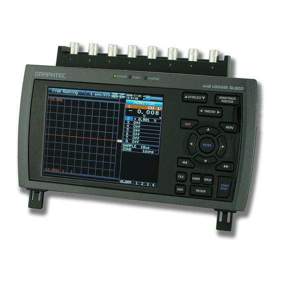
Checks and Preparation 2.3 GL900 Part Names and Functions This section describes the names and function of parts of the GL900. PC interface terminals Monitor Operation status LED Power switch • USB • POWER : ON when the power is ON •... -
Page 19: Connecting The Power Cable And Turning On The Power
(4) Plug the AC cable into the mains power outlet. (5) Press the power switch on the GL900 to the ON side to turn on the power. CAUTION Always connect the GND terminal and refer to the safety precautions. The GL900 must be grounded... -
Page 20: Connecting To A Dc Power Supply
CAUTION Be sure to check the polarity of the wire tips when performing wiring. (5) Press the power switch on the GL900 to the ON side to turn on the power. CAUTION Always connect the GND terminal and refer to the safety precautions. The GL900 must be... -
Page 21: Connecting The Signal Input Cables
1-5 V range. CAUTION Make sure that the GL900 is not pulled by signal input cables when you connect them. The GL900 may fall down if it is pulled.......... High-voltage terminal (terminal for high-voltage input signals) –... -
Page 22: Logic Alarm Cable Connection And Functions
+5 V, 10 KΩ pull-up resistance Contact capacity 5 V to 24 V, 100 mA or below Circuit Example of Relay Drive by Alarm Output Alarm Output Circuit External Device +24V GL900 10KΩ This relay turns ON when alarm is generated. - Page 23 Checks and Preparation Wiring Cable tips are bare tips. Perform wiring for the necessary functions. Signal Name Channel Number Wire Color Logic/Pulse output Orange with red dotted line Orange with black dotted line Grey with red dotted line Grey with black dotted line Alarm output White with red dotted line White with black dotted line...
-
Page 24: Attaching Usb Memory
Attach the USB memory to the USB memory terminal. USB memory CAUTION When you attach the USB memory to GL900, be careful during handling so as not to bump or drop the unit. <Specifications of supported USB memory> • Power source : +5 V •... -
Page 25: Connecting To A Pc
Manual" in an attached CD-ROM. CAUTION The USB connector is adjacent to the LAN connector. Make sure the cable is inserted into the correct connector. Use an A-B type USB cable to connect the GL900 to a PC A connector B connector 2-10... -
Page 26: Lan Connection
Checks and Preparation LAN Connection Use a LAN cable to connect the GL900 to a PC. LAN cable Cable Types • Use a crossing cable when connecting directly to a PC, without using a hub. LAN cable (crossing) • Use a straight cable when using a hub. -
Page 27: Using The Battery Pack (Option)
(2) Attach the battery pack (B-517: option). CAUTION When you have the GL900 run on batteries, be sure to mount two battery packs with the same charge level. Do not use a new battery with an old battery at the same time. -
Page 28: Charging The Battery
When charging is attempted while the power is ON, charging may not be performed immediately depending on the temperature environment. In such a case, set the Screen Saver settings to ON. GL900 will start charging as soon as it is cooled down. -
Page 29: Connecting The Humidity Sensor (Option)
2.10 Connecting the Humidity Sensor (Option) Connect the + and - lead wires of the humidity sensor (the B-530 option) to the desired terminals, and then insert the round connector into the 5V OUT connector on the GL900. Humidity sensor... -
Page 30: Precautions To Observe When Performing Measurement
250 Ω (±0.1%) resistor and measure it in the 1-5 V range. CAUTION Make sure that the GL900 is not pulled by signal input cables when you connect them. The GL900 may fall down if it is pulled. 2-15... -
Page 31: Noise Countermeasures
Connect the signal chassis GND and the measurement device chassis ground. Use a short, thick lead to connect the chassis GND of the measurement object to the GL900’ chassis GND. It will become even more effective if the ground potentials are the same. -
Page 32: Setting The Date And Time
If the GL900 is not used for a period of approximately six months, the internal rechargeable battery may be discharged and the date and time may revert to the initial settings. If this happens, recharge the battery before using the GL900. -
Page 33: Settings And Measurement
CHAPTER Settings and Measurement This chapter describes the setting and measurement procedures for the GL800. Window names and functions Key Operation Operation Modes Setting Menus WEB Server Function... -
Page 34: Window Names And Functions
: Waiting for the time set on the timer : Capturing data and replaying captured data : Capturing data to the internal RAM of the GL900 : Capturing data to the internal flash memory of the GL900 : Capturing data to USB memory : Auto-saving data (Data captured in the internal RAM is being saved to the internal flash memory or USB memory.) - Page 35 For details on the key lock status, see page 3-46. 6. Remote display : The GL900 is in local mode. The GL900 can be operated from itself. : The GL900 is in remote mode. The GL900 can be operated from a PC except for some operations.
- Page 36 Settings and Measurement 9. Digital display Displays the input values for each channel. The SPAN/TRACE/POSITION key is used to change the display. The keys or the CH SELECT key can be used to select the active channel (enlarged display). Moreover, the selected active channel is displayed at the very top of the waveform display.
- Page 37 Settings and Measurement 14. Scale lower limit Displays the lower limit of the scale of the currently active channel. 15. Waveform display Displays the waveform of the input signal. 16. Scale upper limit Displays the upper limit of the scale of the currently active channel. 17.
-
Page 38: Key Operation
Settings and Measurement 3.2 Key Operation This section describes key operation. 1. CH SELECT 2. SPAN/TRACE/POSITION 3. TIME/DIV 5. QUIT 4. MENU 6. Direction keys 7. ENTER 8. FAST FORWARD key (KEY LOCK) 9. START/STOP (USB DRIVE) 13. FILE 14. NAVI 11. -
Page 39: Span/Trace/Posion
Settings and Measurement 2. SPAN/TRACE/POSITION Switches the display in the digital display. Used to change the settings related to waveform display during Free Running (when stopped), data capture, and data replay. Pressing this key will switch displays as shown below. MONITOR SPAN POSITION... -
Page 40: Menu
Settings and Measurement 4. MENU Open the settings window to capture data. For details on settings, see Section 3.4, "Setting Menus" on page 3-17. 5. QUIT The key is primarily used for the following operations. • To cancel a setting during menu configuration. •... -
Page 41: Enter
Settings and Measurement 7. ENTER This key is primarily used for the following operation: • To finalize setting items during menu configuration or open submenus. 8. FAST FORWARD keys (KEY LOCK) These keys are primarily used for the following operation. •... -
Page 42: Review
(3) The external storage media is recognized by the PC and data exchange becomes possible. * In USB Drive Mode, the display on the GL900 is as shown below. CAUTION • To cancel the USB Drive Mode, reboot the MT100. -
Page 43: Display
Pressing this key switches the window display as follows: <Waveform + Digital Screen> Displays waveforms and digital values. This is the default screen when the GL900 is powered on. The screen settings can be changed by using the SPAN/TRACE/POSITION key. -
Page 44: Cursor(Alarm Clear)
Settings and Measurement 12. CURSOR(ALARM CLEAR) This key has different roles in different operation statuses. <When replaying captured data> This key is used to toggle between cursors A and B during replay. • Waveform + Digital Screen Cursor B Cursor A Cursor B Cursor A Cursor A is in blue when selected or in gray otherwise. -
Page 45: File
Settings and Measurement 13. FILE • Replays data in the internal flash memory and USB memory. • This key is used for operations related to the internal flash memory and USB memory (such as copy and delete) • Saves data in the internal RAM to the internal flash memory and USB memory. -
Page 46: Operation Modes
Settings and Measurement 3.3 Operation Modes You can check the system operation status in the simplified message display. Operation Operation Operation Free Running Start up status or data is not being Free Running captured Capturing Data is being captured in the main Capturing to Internal RAM, Capturing to Internal Flash memory or USB device. -
Page 47: Capturing
Settings and Measurement (2) Capturing Capture time Note: "+++++:++:++" is displayed Time of Capturing when the capture time is long. Capture file name During data capture, data is captured into the Internal memory or USB device. You cannot use the MENU key to change the setting. Operations available for change during capturing SPAN/TRACE/POSITION The SPAN/TRACE/POSITION key is used to change settings. -
Page 48: Replaying
Settings and Measurement (4) Replaying This area displays voltages, etc. of points indicated by Cursor A or B or the selected cursor. This area displays measuring time, etc. of points indicated by Cursor A or B or the selected cursor. Displays captured data. -
Page 49: Setting Menus
Settings and Measurement Setting Menus When you press the MENU key during Free Running, the following menu screens appear. The menu screens are classified by the tab for each setting item. DATA TRIG OTHR (1) AMP settings This menu is used to specify input signal-related settings. <Analog settings>... - Page 50 Settings and Measurement Switching displays Analog and Logic/Pulse can be switched as shown below. • Display Logic/Pulse Data • Display Analog Data A screen switches with ENTER key. Analog settings This screen allows you to set conditions for analog signals. CHECKPOINT ALL and Span All Settings are set only for the currently displayed group (per 10 channels).
- Page 51 Settings and Measurement Available SPAN Settings <Voltage Ranges> Range Maximum SPAN (measurement range) Minimum SPAN Minimum resolution 20mV -22.000 to +22.000mV 0.200mV 0.001mV 50mV -55.00 to +55.00mV 0.50mV 0.01mV 100mV -110.00 to +110.00mV 1.00mV 0.01mV 200mV -220.00 to +220.00mV 2.00mV 0.01mV 500mV -550.0 to +550.0mV...
- Page 52 Settings and Measurement (1)-4 EU (Scaling) Converts the measured signals to other units. Setting Description Function Sets the function to ON or OFF. Meas. Value Sets the upper and lower limits of the numeric value to be converted. (Upper and Lower Limits) EU Output Value Sets the upper and lower limits of the output value after conversion.
- Page 53 Settings and Measurement (1)-5 Misc. Setting Description Span Sets the upper and lower limits of the span in which waveforms should be displayed. Annotation Sets an annotation (comment) to be displayed for each channel. The annotation can be 11 characters long at the maximum. You can use alphanumeric and kana characters and symbols.
- Page 54 Settings and Measurement (1)-9 Slope Sets the slope (direction) to count the number of pulses. This item can be set only when Pulse is selected in (1)-6. Setting Description ↑ H Counts the rising edges of pulses. ↓ L Counts the falling edges of pulses. (1)-10 EU (Scaling) Converts the measured signals to other units.
- Page 55 Settings and Measurement (2) DATA settings This menu is used to specify setting items related to capture and calculations. <Capturing data to the internal RAM> <Capturing data to the internal flash memory or USB memory> Setting Selection Sampling Interval 10, 20, 50, 100, 200, 500 us; 1, 2, 5, 10, 20, 5 Data capture destination Internal RAM, Internal Flash Memory, USB Memory [Internal RAM]...
- Page 56 Settings and Measurement (2)-2 Data Capture Destination Specifies the data capture destination for captured data. Selection Description Internal RAM Captures the measured data to the internal RAM. The data will be lost when the power is turned off. The data will be overwritten when next data is captured. Check the waveform and, if it is OK, press the File key to save the data (see page 3-36).
- Page 57 User : Captures data to a file with a user-defined name. File Format Sets the file format in which you want to save data. GBD : Creates a data file in Graphtec proprietary binary format. * Prevents tampering of data. CSV : Creates a data file in a text format.
- Page 58 On. Beware of using this setting particularly when Repeated Capturing is set to On for the trigger (For details, see page 3-26 in the "TRIG Settings." (2)-6 Statistical Calculation Settings The GL900 can perform two statistical calculations. This section describes specifying the statistical calculation settings. Selection Description Calculation is not performed.
- Page 59 Settings and Measurement (3) TRIG Settings This menu is used to specify trigger conditions and alarm settings. Setting Selections available Timer mode Off, Date and Time, Every Day Cycle, Every Hour Cycle [Date and Time] Start side source setting Date January 1, 2005 to December 31, 2035 Time 00:00 to 23:59 (Hour:Minute)
- Page 60 Settings and Measurement (3)-1 Timer Mode Sets the timer function. When the timer function is used (set to a selection other than OFF), data capture is enabled only during the time for which the timer is set. Selection Description The timer function is not used. Data capture starts according to triggers. Date and Time Data capture starts when a trigger is generated only during certain (specified) date and time.
- Page 61 Settings and Measurement (3)-4 Pre-trigger Specifies the percentage of data to be captured before a trigger is generated. * Pre-trigger can be selected only when the data capture destination is the internal RAM and the start side source setting is other than OFF. If the pre-trigger is 30% Time available for data capture Start side trigger...
- Page 62 Settings and Measurement Trigger Level Settings/Alarm Level Settings If the start side source setting or stop side source setting is "Level", specify detailed conditions for each channel. The overall structure of level triggers are as shown below. CH n Mode Level CH n Mode...
- Page 63 Settings and Measurement About Level and Edge Operations In the level operation, the trigger conditions are assumed to be met only if they are met when the START key is pressed (after the timer reaches the set time). In the edge operation, the trigger conditions are assumed NOT to be met even if they are met when the START key is pressed (after the timer reaches the set time).
- Page 64 (4)-2 USB Setting Sets the USB ID number of the GL900. Specify a number from 0 to 9. When you control more than one unit of the GL900 with one PC, assign a unique USB ID to each of them CAUTION You must restart MT100 after any change is made to a setting value.
- Page 65 Settings and Measurement (4)-3 TCP-IP Settings Specifies TCP-IP settings used to connect the GL900 to an Ethernet. Setting items Description IP Address Sets the IP address of MT100 (0 to 255 . 0 to 255 . 0 to 255 . 0 to 255).
- Page 66 Sets the brightness of the LCD backlight. (5)-2 Screen Saver Automatically turns off the display if the GL900 is not operated within a specified interval. Turning off the display frequently using the screen Saver function allows longer lifetime of the LCD screen.
- Page 67 Sets the clock of the GL900. Sets the built-in clock (Date/Time) of the GL900. If Network Time is set, the clock of the GL900 is automatically adjusted via the network. For details, see "Network Time Settings" on the next page.
- Page 68 Settings and Measurement Network Time Settings The GL900 has a feature of synchronizing the time of the built-in clock with that of a time server via an Ethernet. This menu is used to make settings required to use this feature.
- Page 69 Specifies a file to which you want to save data. For details, see the file box on page 3-39. (6)-4 Bitmap Save The GL900 can save a screen copy of waveforms, etc. to a bitmap file. This menu is used to specify the save destination, file name, etc. of a bitmap file.
- Page 70 UG (Guest) U1 (User 1) U2 (User 2) CND ....Data format (Settings file format of the GL900) User : Captures data to a file with a user-defined name. (6)-7 Load Loads the settings of the GL900 from a file.
- Page 71 Settings and Measurement (7) File Box Use the file box to specify a data save destination from the DATA menu or to operate a disk from the FILE menu as follows: <File box for File Operation> <File box for File Replay> Description Changes the operation of the file box.
- Page 72 Settings and Measurement Use the key to move to the target folder. Use the key to select [Create new folder]. Press the ENTER key. In the [New folder name] box that appears, type in "TEST". Use the key to choose [Select file/folder]. Use the key to move the cursor to the created "TEST"...
- Page 73 Settings and Measurement Select [OK] to close the screen. (8) Text Input This menu is used to specify the settings of text input operations such as annotation, EU (scaling) unit and captured data file name input. • Operation Operation mode Description Operation method Text input...
- Page 74 Settings and Measurement (9) Data Replay Menu When you press the MENU key during replay, the Data Replay Menu is displayed. Setting Selections available Cursor Position Move to First Data Execute Move to Last Data Execute Move to Center Execute Move to Trigger Position Execute Move to...
- Page 75 Settings and Measurement (9)-4 Move to Trigger Position Moves the currently selected cursor (A or B) to the trigger position. (9)-5 Move to Selected Position Moves the currently selected cursor (A or B) to a selected position (relative position in time) or a specific point in time.
- Page 76 Performs calculation between cursors. Opens a window and displays calculation results when Execute is selected. (9)-12 X-Y Display Settings The GL900 can convert waveform data to X-Y display. This menu is used to assign channels and make other settings to convert the data to X-Y display. 3-44...
- Page 77 Settings and Measurement Setting Selections available X-ch Sets a channel to be assigned to the X-axis in each zone. Y-ch Sets a channel to be assigned to the Y-axis in each zone. Trace Turns on or off the display in each zone. On : Turns on the display of waveforms.
- Page 78 Settings and Measurement Screen Operation mode Content Explanation Waveform Free Running SAMPLE key can be used to change the sampling interval. ZONE key can be used to change the zone division. Recording ZONE key can be used to change the zone division. Capturing and Replaying ZONE key can be used to change the zone division.
-
Page 79: Web Server Function
• http ........Protocol to access the server. HTTP (Hyper Text Transfer Protocol) • IP address ......Type in the IP address of the GL900 to monitor. • index.html ......File name. This is fixed to index.html. • Procedure 1. - Page 80 Zoom ........Enlarges only the LCD screen of GL900. Digital ........Displays the GL900 measured value digitally. Download of device file ..Allows data captured with GL900 to be downloaded to your PC via FTP. Graphtec Web site ....Accesses to our Web site.
- Page 81 Settings and Measurement • Zoom CH SELECT ......Press this switch to move the active channel in the Waveform + Digital or X-Y screen. DISPLAY ......Switches the display mode. Press this key to switch among Waveform + Digital, Expanded Waveform, Digital screens, and X-Y display.
- Page 82 • Upload file • Delete file/folder • Create file/folder • Change file name/folder name To enable data to be written to the GL900, the login account name must be changed. please use the following table as a guide. Account name Password...
-
Page 83: Specifications
CHAPTER Specifications This chapter describes the basic specifications for the GL900. Standard Specifications Function Specifications Accessory/Option Specifications External Dimensions... -
Page 84: Standard Specifications
Equivalent to automobile parts Type 1 Category A classification *1 Excluding the AC adapter and batteries *2 Two battery packs (B-517: option) are required for the GL900 to run on batteries. For details, see Section 2.9, "Using the Battery Pack (B-517: Option)". -
Page 85: Internal Memory Devices
Data transfer to the PC (realtime, memory) Control of the GL900 from the PC Ethernet functions Web server function : Displays GL900's screen image on Web browser and operates (10BASE-T, 100BASE-TX) the GL900 from the Web browser. FTP server function : Transfers and deletes files from internal memory and USB memory. -
Page 86: Input Unit Specifications
Specifications Input Unit Specifications Item Description Number of input channels Fixed to 8 channels Input terminal Voltage BNC connector type Temperature M3 screw type terminal board Input method All channels isolated Imbalanced input Simultaneous sampling of all channels 10 μs Maximum sampling speed Measurement Voltage... -
Page 87: Function Specifications
Specifications 4.2 Function Specifications Function Specifications Item Description Display screen Waveform screen + Digital screen Expanded Waveform screen Digital screen X-Y display * Even during data capture, you can open menus (to check whether setting is possible). * Screens can be key-toggled. EU (scaling function) 4 points can be set for each channel. -
Page 88: External Input/Output Functions
Specifications External Input/Output Functions Item Description Input/output types Trigger input (1 ch) Logic input (4 ch) or Pulse input (4 ch) Alarm output (4 ch) * Switch between Logic and Pulse Input specifications Maximum input voltage : 0 to +24 V (single-ended ground input) Input threshold voltage : Approx. -
Page 89: Accessory/Option Specifications
Item name Description Quantity Quick Start Guide GL900-UM-8xx CD-ROM GL900-CDM0xM (User Manual, Application Software) Guarantee Card Provided for a domestic model AC adapter 100 to 240 VAC, 50/60 Hz, Power supply cord for each area 1 set Battery Pack B-517 (Option) -
Page 90: Humidity Sensor B-530 (Option)
1.1 m (stationary surface probes) K-type thermocouple RIC-430 1.1 m (stationary surface L probes) *1: Two battery packs (B-517: option) are required for the GL900 to run on batteries. For details, see Section 2.9, "Using the Battery Pack (B-517: Option)". -
Page 91: External Dimensions
Specifications 4.4 External Dimensions 24.6 Dimensional precision: ±5mm Unit: mm... - Page 92 Index Index AC Power Supply, Connecting ......2-4 Edge Operations ..........3-31 Accessory ENTER key ............3-9 Accessory Specifications ......4-7 EU (Scaling) ........... 3-20, 3-22 Checking the Accessories ......2-2 External Dimensions .......... 4-9 Alarm External Input/Output Function Specifications ... 4-6 Hold Generated Alarm ........
- Page 93 Index Signal Types ............2-6 MENU key ............3-8 SPAN ..............3-7 Mode ............3-14, 3-30 Span setting ..........3-7, 3-21 MONITOR ............3-7 SPAN/TRACE/POSITION key ......3-7 Monitor Standard Accessories ........2-2 Monitor Specifications ........4-3 Standard Specifications ........4-2 Notes on Using the Monitor ......
-
Page 94: Index
Index... - Page 95 Index...
- Page 96 The specifications, etc., in this manual are subject to change without notice. GL900-UM-151 June 1, 2008 1st edition-01 GRAPHTEC CORPORATION...
- Page 97 503-10 Shinano-cho, Totsuka-ku, Yokohama 244-8503, Japan Tel : +81 (045) 825-6250 Fax : +81 (045) 825-6396 Email : info@graphteccorp.com Web : www.graphteccorp.com Printed in Japan...
Need help?
Do you have a question about the GL900 and is the answer not in the manual?
Questions and answers