Kärcher Puzzi 8/1 C Unit Information
Hide thumbs
Also See for Puzzi 8/1 C:
- Original instructions manual (204 pages) ,
- Instruction manual (172 pages) ,
- Operating instructions manual (32 pages)

Related Manuals for Kärcher Puzzi 8/1 C


Summary of Contents for Kärcher Puzzi 8/1 C
- Page 1 New Unit Information Puzzi 8/1 C 1.100-200.0 New Unit Information 05.2007 5.906-335.0...
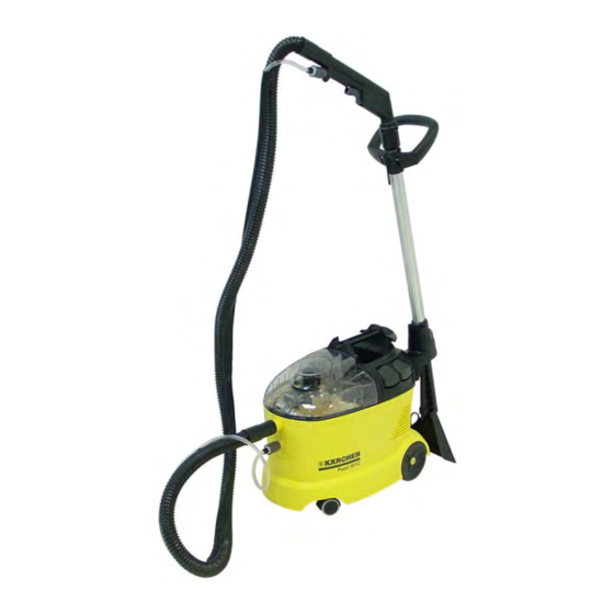
- Page 2 Technical features Puzzi 8/1 C General – Wet cleaner for cleaning carpets for commercial use in hotels, shops, offices, etc. – Tank volume: Fresh-water tank = 8 l Wastewater tank = 7 l – Noise emission 71 dB(A). – Floor tool for carpets, working width 230 mm.
- Page 3 Puzzi 8/1 C Unit functions View from the front 1 Bracket, floor tool with suction tube 7 Unit housing, lower section 2 Carrying handle and suction tube storage 8 Wheel (2x) during transport 9 Swivel casters (2x) 3 Filler opening, fresh water...
- Page 4 Unit functions Puzzi 8/1 C Rear view 5 Unit housing, lower section 1 Carrying handle and suction tube storage during transport 6 Bracket, upholstery tool (optional) 2 Mains cable retractor 7 Mains cable 3 Unit housing, upper section 8 Bracket, floor tool with suction tube...
- Page 5 Puzzi 8/1 C Unit functions View from above, wastewater tank cover removed 1 Connection, suction hose 9 Unit housing, upper section 2 Wastewater channel 10 Bracket, upholstery tool (optional) 3 Wastewater tank 11 Bracket, floor tool with suction tube 4 Handle, wastewater tank...
- Page 6 Unit functions Puzzi 8/1 C Fresh-water tank Water filter Filters contaminations out of fresh water in order to prevent damage to the water pump (M2). Water filter „MAX“ mark The „MAX“ mark (3) in the fresh-water tank (2) indicates the maximum water quantity, which may be added to the fresh-water tank (2).
- Page 7 Puzzi 8/1 C Unit functions Unit housing, wastewater tank removed 1 Unit housing, lower section Fluff strainer 2 Air intake (drawn in air) opening with fluff Filters coarse contaminations out of the drawn in strainer air in order to prevent damage to the suction motor (M1).
- Page 8 Unit functions Puzzi 8/1 C Unit housing, upper section removed 1 Unit housing, upper section 2 Sealing strip 3 Switch (S2), water pump (M2) 4 Switch (S1), suction motor (M1) 5 Unit housing, lower section Page 8 / 29 New Unit Information 05.2007...
- Page 9 Puzzi 8/1 C Unit functions View from below 1 Fresh-water hose to the spray/ suction 5 Air discharge, motor cooling air hose 6 Retaining screw, RH wheel 2 Floor cover 7 Wheel, RH 3 Wheel, LH 8 Retaining screws (9x), floor cover...
- Page 10 Unit functions Puzzi 8/1 C Transport The spray / suction tube is pressed onto the carrying handle (2) for transporting the unit. The suction / spray hose is inserted in the hook (3). 1 Spray / suction tube 2 Carrying handle and suction tube storage...
- Page 11 Puzzi 8/1 C Unit functions Printed circuit board (N1) 1 Terminal strip (X1), switch (S2), water pump (M2) 2 Terminal strip (X3), switch (S2), water pump (M2) 3 Terminal strip (X5), switch (S1), suction motor (M1) 4 Terminal strip (X7), switch (S1), suction...
- Page 12 Unit functions Puzzi 8/1 C Spray / suction hose 1 Spray / suction hose 2 Fresh-water hose 3 Connection sleeve, suction hose 4 Connection, fresh-water hose 5 Handle section 6 Lever, spray function release 7 Threaded connection, connection to the...
- Page 13 Puzzi 8/1 C Unit functions Spray / suction tube Threaded connection The threaded connection (2) is used to connect the handle section (see Page 12, Item 5) and the floor tool (4) with the spray / suction tube. – Open threaded connection (left-hand thread) (3) and push onto the spray / suction tube.
- Page 14 Unit functions Puzzi 8/1 C Spray / suction tube Spray nozzle The spray nozzle (1) sprays the fresh water - cleaning agent mixture onto the carpet to be cleaned. Spray nozzle on the floor tool Guide handle The guide handle (2) can be used to exert an...
- Page 15 Puzzi 8/1 C Circuit diagram Circuit diagram 0.088-980.0 New Unit Information 05.2007 Page 15 / 29...
-
Page 16: Circuit Diagram
Circuit diagram Puzzi 8/1 C Circuit diagram 0.088-980.0 C1 Capacitor F1 Fuse (in Japan version only) M1 Suction motor M2 Water pump N1 Printed circuit board S1 ON/OFF switch, suction motor S2 ON/OFF switch, water pump V1 Diode X1 Mains plug Page 16 / 29 New Unit Information 05.2007... - Page 17 Puzzi 8/1 C Basic settings and service procedures Unit switch Replacing switches If one of the switches (S1) or (S2) is defective, it can be removed and replaced as follows. – Remove the retaining screws (1). – Remove switch elements bracket (2).
- Page 18 Basic settings and service procedures Puzzi 8/1 C Unit switch Replacing switches – Pull the relevant switch (1, 2) out of the bracket. – Remove the cable connections from the rele- vant switch (1, 2) and note the cable assignment at the switch.
- Page 19 Puzzi 8/1 C Basic settings and service procedures Floor cover removed 1 Air discharge, motor cooling air Remove floor cover 2 Sound insulation – Remove retaining screws (see Page 9, Item 8). 3 Holder, suction motor – Remove floor cover.
- Page 20 Basic settings and service procedures Puzzi 8/1 C Suction motor cover removed 1 Air discharge, motor cooling air Remove suction motor 2 Sound insulation – Pull the suction motor (3) out of the suction motor holder (5). 3 Suction motor (M1) –...
- Page 21 Puzzi 8/1 C Basic settings and service procedures Suction motor 1 Holder, suction motor Replacing the carbon brushes 2 Carbon brushes – Remove the retaining screws (3). 3 Retaining screws, carbon brushes – Remove carbon brushes (2). 4 Cable connection, suction motor –...
- Page 22 Basic settings and service procedures Puzzi 8/1 C Water pump 1 Rubber mounts (2x), water pump Removing the water pump 2 Water pump (M2) – Remove floor cover (see Page 19). 3 Hose clamp – Remove water pump (2) with the rubber mounts (1) from the holder (5).
- Page 23 Puzzi 8/1 C Basic settings and service procedures Wheel Replacing the wheel – Remove the retaining screw (2). – Pull the wheel (1) out of the holder (3). – Install new wheel in reverse order. Wheel installed Wheel, retaining screw removed...
- Page 24 Basic settings and service procedures Puzzi 8/1 C Spray nozzle Replacing the spray nozzle The spray nozzle (3) is inserted in the spray tube (2) and is held by two latching tabs (1) on the left and right. If it is defective or blocked it can be replaced as follows: –...
- Page 25 Puzzi 8/1 C Basic settings and service procedures Guide handle Adjusting the guide handle The guide handle is pushed onto the spray / suction tube and is attached with two Allen screws. – Loosen Allen screws (2) with an Allen key (4).
-
Page 26: Troubleshooting
Troubleshooting Puzzi 8/1 C Troubleshooting Faults Solution No water discharge at the – Check/top up water level in the fresh-water tank. nozzle – Check connections at spray/suction hose for correct fit/wear. – Check spray nozzle for blockage - clean/replace. – Check water filter in fresh-water tank for blockage - clean/ replace. -
Page 27: Technical Specifications
Puzzi 8/1 C Technical specifications Technical specifications Unit type Unit No. Circuit dia- Operating Spare parts gram instructions list Puzzi 8/1 C 1.100-200.0 0.088-980.0 5.962-081.0 5.970-682.0 The technical data sheet and the circuit diagram will be included in the next issue of the spare parts CD-ROM (DISIS) and are also available in kaercher-inside (https://kaercher-inside.com). - Page 28 Index Puzzi 8/1 C Index Fresh-water hose to the spray/ suction hose ......... 9, 19, 20, 22 Accessories (optional) ........2 Fresh-water tank ........5, 6 Adjusting the guide handle ......25 Fuse (in Japan version only) ......16 Air duct, drawn in air from floor tool ....19 Air intake opening with fluff strainer ..
- Page 29 Puzzi 8/1 C Index Index Retaining screw, wheel ........ 23 Terminal strip (X3), switch (S2), Retaining screws (2x), bracket, water pump (M2) .......... 11 switch element ..........17 Terminal strip (X4), water pump (M2) ... 11 Retaining screws (2x), bracket, Terminal strip (X5), switch (S1), switch element ..........