
Related Manuals for Kärcher Puzzi 30/4


Summary of Contents for Kärcher Puzzi 30/4
- Page 1 Puzzi 30/4 Service Manual English 5.905-007.0 Rev. 00 (06/14)
-
Page 2: Table Of Contents
Contents Preface Safety instructions Danger or hazard levels Description in this service manual Service groups Functional group structure Textual description Technical Features General Tools used Field of application Safety installations Type plate Overview of the appliance Front view View from behind Overview service cover removed Overview cover at the bottom removed Overview of the components... - Page 3 040 Service activities Uninstall / install water pump Uninstall / install hose from pump to the spray hose connection Uninstall / install spray hose connection Uninstall / install hose from the fresh water tank to the water pump Uninstall / install float switch Uninstall / install heating rods Clean/ replace fresh water sieve Uninstall / install water level indicator...
-
Page 4: Preface
Preface Good service work requires extensive and practice-orient- ed training as well as well-structured training materials. Hence we offer regular basic and advanced training pro- grammes covering the entire product range for all service engineers. In addition to this, we also prepare service manuals for im- portant appliances - these can be initially used as instruc- tion guides and later on as reference guides. -
Page 5: Safety Instructions
Safety instructions Service and maintenance tasks may only be performed by CAUTION qualified and specially trained specialists. Risk of damage by electrostatic discharge (ESD)! Take Observe safety information in the chapters! suitable measures for discharging electrostatic charge pri- or to performing work on the appliance electronics. DANGER First pull out the plug from the mains before carrying out any tasks on the machine. -
Page 6: Technical Features
Technical Features General This spray extraction device is used as a wet cleaning de- vice for carpets. It can be adapted to the relevant cleaning task by setting the rotary switch. The wastewater tank can be removed for easier emptying. A capacity of the fresh and waste water tank of 30 l allows effective cleaning with long action times. -
Page 7: Field Of Application
Field of application This service manual describes the appliance Puzzi 30/4. Safety installations Safety devices serve to protect the user and must not be rendered in operational or their functions bypassed. Observe safety information in the chapters! Type plate The type plate is located at the back on the service cover. -
Page 8: Overview Of The Appliance
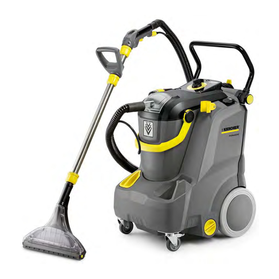
Overview of the appliance Front view Suction hose Pushing handle, adjustable Rotating knob Fastening screw for push-handle Socket for additional brush washing head PW 30/1 X2 Holder for suction pipe Impeller Fresh water sieve Steering roller with fixed position brake 10 Floor nozzle for carpet cleaning 11 Lid of the fresh water tank 12 Dirt water reservoir, detachable... -
Page 9: View From Behind
View from behind Nameplate Adapter for accessories (homebase) including cable hooks Power cord Service cover Filling level display English 5.905-007.0 Rev. 00 (06/14) -
Page 10: Overview Service Cover Removed
Overview service cover removed Suction turbine Appliance electronics Hose to the spray hose connection Reset button Hose from the fresh water tank Water pump Suction air tube Reset button When filling in hot water from approx. 65-70°C, the heat sensor switches off the electronics. The electronics can be reset with the reset button. -
Page 11: Overview Cover At The Bottom Removed
Overview cover at the bottom removed Float switch Heating rods Hose from the fresh water tank to the water pump English 5.905-007.0 Rev. 00 (06/14) -
Page 12: Overview Of The Components
Overview of the components English 5.905-007.0 Rev. 00 (06/14) - Page 13 English 5.905-007.0 Rev. 00 (06/14)
- Page 14 English 5.905-007.0 Rev. 00 (06/14)
- Page 15 English 5.905-007.0 Rev. 00 (06/14)
-
Page 16: Ab Service Group Bodywork / Chassis
AB service group bodywork / chassis 010 Safety information General Observe general safety information! Service and maintenance tasks may only be performed by qualified and specially trained specialists. DANGER First pull out the plug from the mains before carrying out any tasks on the machine. -
Page 17: 030 Function
030 Function Casing In the casing Rotating knob – Fresh water tank – Suction turbine – Water pump – Appliance electronics – Chassis – are installed 040 Service activities Uninstall / install push handle Unscrew the screws on both sides of the push handle. ... -
Page 18: Uninstall / Install Steering Roller
Uninstall / install steering roller Unscrew the screws. Remove steering roller. Loosen the nut. English 5.905-007.0 Rev. 00 (06/14) -
Page 19: Uninstall / Install Running Wheel
Uninstall / install running wheel Remove the wheel cover. Lever the clamping washer off the axle. Use a new clamping washer upon installation. Remove the service cover Unscrew the screws. Put the service cover aside. English 5.905-007.0 Rev. -
Page 20: 050 Maintenance And Inspection
050 Maintenance and inspection Check wheels for ease of movement. Check whether the axle is bent. 060 Error diagnosis Findings Possible cause Correction Damage, cracks External mechanical impact Replace casing, instruct operator Casing distorted Thermal impact Replace casing 070 Peculiarities/ others The service group does not contain any peculiarities. -
Page 21: Ac Service Group Suction System
AC Service group suction system 010 Safety information For this service group there is no special safety informa- tion. Observe general safety information! 020 Overview 030 Function Wastewater is sucked through the suction hose into the waste water tank via the floor nozzle. The suction turbine generates the necessary vacuum in the wastewater tank. -
Page 22: Uninstall / Install Waste Water Cover
040 Service activities Uninstall / install waste water cover Pull suction hose off the waste water cover. Completely fold out the waste water cover. Pull out of the retainers towards the back. Replacing the seal of the waste water cover ... -
Page 23: Uninstall/ Install Suction Turbine
Remove the suction nozzle from the retainer towards the top. Uninstall/ install suction turbine Remove the cover of the service unit. Unscrew the screws on the strain relief. Unscrew the screws. Remove the suction turbine with the holder. English 5.905-007.0 Rev. - Page 24 Pull out the connecting plug. Remove the suction turbine from the holder. Mind the correct fitting position in the holder upon in- stallation. Note The lugs on the suction turbine casing must be in the re- tainers in the holder. ...
-
Page 25: Uninstall / Install Flat Fold Filter
Uninstall / install flat fold filter Pull suction hose off the waste water cover. Open the cover. Push in the lugs on both sides of the filter casing. Remove the cover of the filter casing. 1 Filter casing 2 Flat fold filter 3 Cover filter casing ... - Page 26 050 Maintenance and inspection Check and clean seals, replace damaged seals. – Check the suction hose for damages. – Check suction hose for clogging. – Check suction hose to see it is leak-proof. – 060 Error diagnosis Findings Possible cause Correction Insufficient vacuum performance Cover not closed.
-
Page 27: Ad Service Group Water System
AD Service group water system 010 Safety information For this service group there is no special safety informa- tion. Observe general safety information! 020 Overview 030 Function Detergent solution/ fresh water is delivered from the fresh water tank by the water pump. Foreign objects and soiling in the cleaning detergent solu- tion/ fresh water are retained by the water filter. -
Page 28: 040 Service Activities
040 Service activities Uninstall / install water pump Remove the cover of the service unit. Unscrew the screws. Sever the cable tie. Remove the hoses from the pump. Disconnect the connectors. Use new cable ties upon installation. Uninstall / install hose from pump to the spray hose connection ... -
Page 29: Uninstall / Install Spray Hose Connection
Unscrew the screws. Sever the cable tie. Pull out the hose. Pull the hose out of the appliance towards the top. Uninstall / install spray hose connection Unscrew the spray hose connection. Uninstall / install hose from the fresh water tank to the water pump ... -
Page 30: Uninstall / Install Float Switch
Tilt the appliance back and rest it. Unscrew the screws. Remove the lid. Sever the cable tie. Remove the hose from the connection. Pull the hose out of the casing. Uninstall / install float switch ... -
Page 31: Uninstall / Install Heating Rods
Uninstall / install heating rods Unscrew the screws. Remove the lid. Disconnect the cable of the heating rods on the appliance electronics. Tilt the appliance back and rest it. Loosen the mounting nuts. Remove the heating rods from the fresh water tank. Clean/ replace fresh water sieve ... -
Page 32: Uninstall / Install Water Level Indicator
Uninstall / install water level indicator Empty the fresh water reservoir. Note The water level indicator is inserted in the casing with a rubber seal at the upper and lower end. Pull the water level indicator out of the casing. Uninstall / install nozzle tip 1 Union joint 2 Nozzle mouth piece... -
Page 33: 050 Maintenance And Inspection
050 Maintenance and inspection Clean the fresh water sieve. – Clean nozzle mouthpiece. – 060 Error diagnosis Findings Possible cause Correction Device is not sucking in detergent Fresh water sieve soiled Clean the fresh water sieve. Spray hose clogged Check the spray hose. Insufficient working pressure Nozzle tip clogged Clean or replace nozzle tip. -
Page 34: Ah Service Group Electrics
020 Overview The illustration serves as an overview over the electrical components of the Puzzi 30/4 C only! Always access the latest circuit diagram in DISIS for work on the appliance. 030 Function The appliance electronics controls all appliance functions. -
Page 35: 040 Service Activities
040 Service activities Unistall / install socket Unscrew the screws. Note Remember the order of the colours of the cables! Take out the socket. Loosen the screws of the cable fastening. Disconnect electrical connections. Reattach the seal upon installation. ... -
Page 36: Uninstall / Install Rotary Switch
Uninstall / install rotary switch Unscrew the screws. Note The screws have different lengths! The two lower screws are shorter than the upper screw. Wedge the rotary knob free. Unscrew the screws. Note Remember the order of the colours of the cables! ... -
Page 37: Uninstall/Install Appliance Electronics
Uninstall/install appliance electronics Remove the service cover. Unscrew the screws. Appliance electronics Heat sensor with reset button Sensor English 5.905-007.0 Rev. 00 (06/14) -
Page 38: Uninstall / Install Heat Sensor
Unscrew the screws. Carefully remove the appliance electronics from the appliance. CAUTION Risk of damage by electrostatic discharge (ESD)! Take suitable measures for discharging electrostatic charge prior to performing work on the appliance electronics. Remove electrical connections from the board. Uninstall / install heat sensor ... -
Page 39: Uninstall / Install Sensor
Uninstall / install sensor Remove the service cover. Remove the cover of the appliance electronics. Disconnect electrical connections. Unscrew the screws. Carefully remove the sensor from the base plate. 050 Maintenance and inspection Service group does not contain any maintenance and in- spection points. -
Page 40: Technical Documentation
Technical Documentation Appliance type Appliance no. Circuit diagram Operating in- Spare parts list structions Puzzi 30/4 *EU 1.101-122.0 0.088-022.0 5.965-059.0 5.972-642.0 Technical specifications Puzzi 30/4 Mains voltage 220-240 Frequency 1~ 50 Type of protection IPX4 Protective class Power Input 1270...
Need help?
Do you have a question about the Puzzi 30/4 and is the answer not in the manual?
Questions and answers