
Related Manuals for Esu LokPilot V4.0


Summary of Contents for Esu LokPilot V4.0
- Page 1 LokPilot V4.0 Instruction Manual 6 . E d i t i o n , F e b r u a r y 2 0 1 3 LokPilot V4.0 LokPilot V4.0 DCC LokPilot micro V4.0 LokPilot micro V4.0 DCC LokPilot V4.0 M4 LokPilot XL V4.0...
-
Page 2: Table Of Contents
6.8.5. Colour Coding by Märklin® ........18 5. Introduction – The LokPilot Family ......7 6.8.6. Motor and track connections ........18 5.1. Overview of the LokPilot V4.0 decoders ......7 6.8.6.1. Connecting DC and Coreless Motors ....18 5.2. Members of the LokPilot Family ........8 6.8.6.2. - Page 3 8.1. Adjustable Properties of Decoders ......28 10.5. Brake sectors ............41 8.1.1. M4 configuration range ...........29 10.5.1. DC brake mode .............41 8.1.2. M4, the mfx® compatible protocol by ESU ....29 10.5.2. Märklin® brake mode ..........41 8.1.1. Configuration Variables (CVs) ........30 10.5.3. Selectrix® Diode Brake Sector ........41 8.1.1.1.
- Page 4 17.2. HAMO magnets ............65 12.2.2.4. „Virtual driving sound” ........54 17.3. Wire harnesses with 8-pole or 6-pole socket .....66 12.2.3. Standard mapping LokPilot V4.0 / micro Decoder ..54 17.4. Mounting adapter 21MTC ........66 12.2.3.1 Example ...............55 12.2.4. Allocation of function keys with the LokProgrammer 55 18.
-
Page 5: Declaration Of Conformity
3. Important Notes – Please read this chapter first Copyright 1998 - 2013 by ESU electronic solutions ulm GmbH & Co KG. Electri- We congratulate you to your purchase of an ESU LokPilot decoder. cal characteristics and dimensions are subject to change without prior notice. -
Page 6: How This Manual Helps You
How this manual helps you 4. How this manual helps you • The LokPilot is exclusively intended for use with model train lay- outs only. It may only be operated with the components listed This manual is divided into several chapters that show you step-by- here. -
Page 7: Introduction - The Lokpilot Family
Introduction – The LokPilot Family 5. Introduction – The LokPilot Family 5.1. Overview of the LokPilot V4.0 decoders LokPilot V4.0 LokPilot V4.0 DCC LokPilot LokPilot LokPilot V4.0 M4 LokPilot LokPilot micro V4.0 micro V4.0 DCC Fx V4.0 XL V4.0 DCC operation Motorola®... -
Page 8: Members Of The Lokpilot Family
All decoders of the LokPilot V4.0 family expand the capabilities of their forerunners by further functions. These developments The LokPilot V4.0 DCC is best suited for the DCC purist who does further improve the driving characteristics, the operational reli- not require multi-protocol operation and does not want to pay ability and the flexibility of the decoders. -
Page 9: Lokpilot Fx V4.0
LokPilot XL V4.0 and LokPilot V4.0 M4 also support operation with M4 and register automatically with Märklin® mfx® central units. 5.2.2. Motor Control The most important function of digital decoders is motor control. -
Page 10: Analogue Mode
11.4. Even with the Märklin® central units 6020®, 6021®, Mobile Sta- The minimum and maximum speed of the LokPilot V4.0 is adjust- tion® and Central Station® all settings are adjusted electronically. able by setting two points which can be optionally adjusted by a Most LokPilot V4.0 decoders support a simple-to-use program-... -
Page 11: Installing The Decoder
Figure 1: LokPilots with NEM652 interface 6.3. Locomotives with 8-pin NEM 652 interface Some LokPilot V4.0 decoders are supplied with an 8-pin interface • Insert the plug of the decoder in such a way that pin 1 of the as per NEM 652 (refer to Fig 1). Installation in locomotives with... -
Page 12: Locomotives With 6-Pin Nem 651 Interface
Installing the Decoder 6.4. Locomotives with 6-pin NEM 651 interface Some LokPilot V4.0 decoders have a 6-pin NEM 651 plug (as per • Insert the plug of the decoder in such a way that pin 1 of the plug Figure 2). Installation in locomotives with this interface is particu-... -
Page 13: Connecting C-Sine Motors („Softdrive-Sinus")
SUSU interface for the exchange of information. The LokPilot V4.0 with the 21MTC interface is suitable for control- ling the C-Sine control electronics provided some parameters are set accordingly. Chapter 11.5. explains the necessary steps. -
Page 14: Loks Mit Plux-Schnittstelle
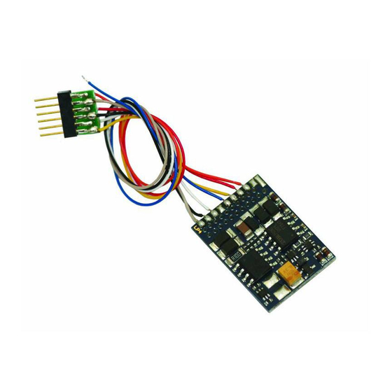
Head violet 54610 LokPilot V4.0 Light Light orange 54611 LokPilot V4.0 DCC 64610 LokPIlot V4.0 M4 Loco hous ing yelllow blue green white black grey black orange grey Figure 5: Wiring diagram for LokPilot V4.0, LokPilot V4.0 DCC (wiring example) -
Page 15: Wiring Diagram For Lokpilot Micro
Wiring Diagram for LokPilot 6.8.2. Wiring Diagram for LokPilot micro Motor grey orange black orange 54683 LokPilot micro V4.0 grey 54687 LokPilot micro V4.0 54684 LokPilot micro V4.0 black white yellow white yellow For decoder back see figure 2). Head Rear Light Light... -
Page 16: Wiring Diagram For Lokpilot Xl Decoders
Wiring diagram for LokPilot XL 6.8.4. Wiring diagram for LokPilot XL decoders Motor + Motor - Head light DC Motor Rear light UVAR AUX1 AUX2 Wheel sensor AUX3 AUX4 Left track AUX5 Right track AUX6 Figure 9: Wiring diagram for LokPilot XL V4.0 (wiring example) 6.8.4.1. -
Page 17: Wiring To An Lgb® Interface
Installing the Decoder 6.8.4.3. Wiring to the Aristocraft® interface yellow=Motor + Many Aristocraft locomotives have a digital interface which repre- sents a manufacturer´s standard only. They are ready for the instal- green= lation of digital components. Motor - The wiring is shown in figure 12: brown= Left track white=... -
Page 18: Colour Coding By Märklin
MUST be removed (also refer to Fig. 14). Please check all connections with an Ohmmeter. Search for short circuits, particularly between the motor leads and the wheel contacts. ESU colour (NMRA Description Märklin® colour DCC Norm) AC: Power pick up show (Center rail) -
Page 19: Connecting Univers. Motors With Hamo-Conversions
After about 1 second, the decoder tries to switch them on again. Should the You may purchase these magnets from your ESU dealer. current still be too high – perhaps due to a short circuit – the same We supply three types of magnets. -
Page 20: Using Leds
Installing the Decoder Voltage R124 UVAR (1,5-3V) 1.5V 33 kOhms 2.5V unsolder 3.0V 48 kOhms, unsolder R125 Head light Rear light The maximum load of the UVAR output is 500mA. 6.9.2. Using LEDs If you like to use LEDs, then a resistor must be wired in series with the LEDs. -
Page 21: Connecting The Light Outputs, Aux1 And Aux2
Connect AUX3 and AUX4 via the 21MTC interface; there are wired in series with the LEDs. It should have a rating of between equal to the other outputs. ESU offers an appropriate adapater 470 Ohms and 2.2 kOhms. Running the LEDs without this resistor board (art.no. -
Page 22: Servo Outputs
Subject to its tolerance levels, it may trigger the overload protection of the de- Servo1 coder. In this case, you must wire a relay (ESU No. 51963) into the (AUX7) circuit or you slightly reduce the „Brightness“ of the output. -
Page 23: Reed Switch Sensor
25V or higher show the desired results). If desired you may con- even need 6 magnets, depending on the cylinder configuration. nect them to the LokPilot V4.0 or LokPilot micro V4.0. Soldering wires onto a decoder requires quality soldering equip- 6.9.7.2. -
Page 24: Optional "Powerpack
6.10.2. Optional “PowerPack” 1N4007 You can solder a powerful energy buffer to all LokPilot V4.0 de- coders. In the lower half of figure 21 we show you how to do it. This „PowerPack“ allows your locomotive to keep running for 2 seconds without power. -
Page 25: Initial Operation
Since not every LokPilot supports all digital systems, we state The address is set to 03 with 14 speed steps. which chapter is applicable for which type. LokPilot V4.0 LokPilot V4.0 DCC LokPilot V4.0 M4 7.2.1. DCC-Betrieb LokPilot micro V4.0 LokPilot micro V4.0 DCC... -
Page 26: Auto-Detection Of Dcc Speed Steps
28-speed step mode. In conjunction with suitable you must interrupt the power to the decoder for a short moment command stations (e.g.: ESU ECoS, in „Motorola® 28“ mode) this in order to activate the auto-detection. leads to smoother control of your locomotives. No changes are required on the decoder. -
Page 27: Selectrix® Mode
Top priority is assigned to DCC with RailComPlus®. Therefore the LokPilot XL V4.0 decoder will always register with RailComPlus and DCC to an ESU ECoS command station, even when M4 is active. You may operate the LokPilot with any Selectrix® compatible If RailComPlus®... -
Page 28: Analogue Ac Operation
The LokPilot V4.0 recognised the Nevertheless, there are plenty of possibilities to influence the be- haviour of the LokPilot decoder by adjusting software-governed pulse for changing direction as usual. -
Page 29: M4 Configuration Range
Since the mfx® data protocol was introduced, it has been pro- For instance, you do not have to enter the value 15 in CV 3 on an tected by Märklin® as a trade mark. This is why ESU decided in mfx® capable command station but rather set the acceleration January 2009 to use the name “M4”... -
Page 30: Configuration Variables (Cvs)
8.1.1. Configuration Variables (CVs) 8.1.1.2. Bits and Bytes Most CVs contain numbers: CV 1 for instance contains the lo- LokPilot V4.0 LokPilot V4.0 DCC LokPilot V4.0 M4 comotive address. This can be any number between 1 and 127. LokPilot micro V4.0 LokPilot micro V4.0 DCC... -
Page 31: Programming With Dcc Systems
Each decoder receiving this command will execute it. justable. Since the display of the 6020 /6021 is limited to two-digit ESU counts the bits from 0 to 7 as laid out in the standards while numbers, values must be split and entered in two separate steps. -
Page 32: Changing To The Programming Mode
Programming 8.2.3.1. Changing to the Programming Mode 8.2.3.3. Long Mode Enter the programming mode with the 6020/6021: You access the long mode by entering the value 07 in CV 07 while in the short mode. The decoder confirms the change to the long The throttle must be set to „0“. -
Page 33: Programming With The Märklin® Mobile Station
Programming 8.2.4. Programming with the Märklin® Mobile Station® 8.2.5. Programming with the Märklin® Central Station LokPilot V4.0 LokPilot V4.0 M4 LokPilot V4.0 LokPilot V4.0 M4 LokPilot micro V4.0 LokPilot micro V4.0 LokPilot XL V4.0 LokPilot XL V4.0 With the Mobile Station®, you can also adjust some of the CVs. -
Page 34: Programming With The Esu Lokprogrammer
Programm the desired value in CV 99. In our example: CV 99 = 120. Due to a severe firmware error the current LokPilot V4.0 decoder As soon as you have programmed CV 99, the value of CV 99 will cannot be programmed with the Multimaus - firmware 1.00. In be transferred into CV 317. -
Page 35: Programming With The Roco® Lokmaus Ii
8.2.8. Programming with the ROCO® LokMaus II Example: You wish to programm CV 317 with value 120. Proceed as follows: LokPilot V4.0 LokPilot V4.0 DCC LokPilot V4.0 M4 • Programm the value of the CV number in hundreds in CV 96. In LokPilot micro V4.0... -
Page 36: Address Settings
(F0) and the auxiliary function F1 to F4. Of course, this is far long address by setting bit 5 in CV 29. too few for the many functions of the LokPilot V4.0. Bit 5 in CV 29 switches between short and long address. The de- Therefore one can assign up to three additional addresses (4 ad- coder can only respond to one address at a time. -
Page 37: Addresses In M4 Mode
For safety reasons the protocol used for writing into CV 47 cannot 137 into CV 49. be turned off. If you use, for instance, an ESU ECOS and write CV 47 in DCC format then the DCC protocol will remain on. If Consecutive addresses are only active in Motorola®... -
Page 38: Adapting The Driving Characteristics
For information on how to set a brake distance independently of ple: start voltage < mid speed < maximum speed. the speed refer to chapter 10.6. LokPilot V4.0 M4 10.1.1. Switching acceleration / deceleration LokPilot decoders can deactivate acceleration and deceleration by the push of a button. -
Page 39: Speed Curve
(CV 5) are supported. You will find more info on this in chapter 10.3. LokPilot XL V4.0 10.3. Speed Curve LokPilot V4.0 M4 and LokPilot XL V4.0 implement the concept of LokPilot V4.0 LokPilot V4.0 DCC the mfx® speed curve. That means that the speed curve is always LokPilot micro V4.0... -
Page 40: Changing From Digital To Analogue Ac
Adapting the Driving Characteristics 10.4.4. Changing from Digital to Digital LokPilot V4.0 LokPilot V4.0 M4 If the DC brake mode is active in CV 27 then the locomotive will slow down to a stop with the programmed deceleration, if not, LokPilot micro V4.0... -
Page 41: Brake Sectors
Adapting the Driving Characteristics 10.5.2. Märklin® brake mode LokPilot Fx V4.0 LokPilot V4.0 LokPilot V4.0 M4 Perhaps you have disabled analogue mode on your decoder (bit 2 LokPilot micro V4.0 in CV 29 is deleted). When the locomotive moves from the digital LokPilot XL V4.0... -
Page 42: Abc "Slow Approach" Section
Adapting the Driving Characteristics As a new function the LokPilot V4.0 decoder supports the ABC 10.6. Constant brake distance braking technique introduced by Lenz®. In order to use this func- LokPilot V4.0 LokPilot V4.0 DCC LokPilot V4.0 M4 tion a group of anti-parallel diods will be be soldered to one half LokPilot micro V4.0... -
Page 43: Linear Braking Distance
10.7.1. DC analogue operation continues to drive ahead for some time when entering the brak- LokPilot V4.0 LokPilot V4.0 DCC LokPilot V4.0 M4 ing section to finally brake within the braking time indicated in CV253. The effort of the braking effect is now constant as set in LokPilot micro V4.0... -
Page 44: Ac Analogue Operation
Adapting the Driving Characteristics 10.7.2. AC analogue operation 10.8. Motor brake LokPilot V4.0 LokPilot V4.0 M4 LokPilot XL V4.0 LokPilot XL V4.0 LokPilot Fx V4.0 In AC analogue mode you can adjust the starting speed with CV If so desired the LokPilot XL V4.0 decoder can short circuit the 127 and the maximum speed with CV 128. -
Page 45: Motor Control
11.1.2. Adjustments for other motors / „Fine Tuning“ Unfortunately, the motors available in the market have consider- LokPilot V4.0 LokPilot V4.0 DCC LokPilot V4.0 M4 able variations due to tolerances. This is even true for the same type. Therefore, LokPilot decoders enable you to adapt load com- LokPilot micro V4.0... -
Page 46: Reference Voltage
Increase the value by 5 starting with the default value for motors 11.1.2.4. Parameter “K slow” with very small or no flywheels. Together with the LokPilot V4.0 decoder an additional CV 52 has • Reduce the value by 5 starting with the default value for motors been introduced which separately determines the gain control with large flywheels. -
Page 47: Adaptive Regulation Frequency
You can also switch off load compensation by writing the value 0 in CV 56 („Control Influence“). LokPilot V4.0 decoders offer a feature for automatic calibration of the motor. I most cases this procedure leads to excellent load With load control turned off, the starting voltage in CV 2 should compensation characteristics. -
Page 48: Settings For The C-Sinus Motor
LokPilot on output AUX4. AUX4 must therefore be active while the locomotive is stopped and while it is moving (in both directions!). LokPilot V4.0 LokPilot V4.0 DCC LokPilot V4.0 M4 LokPilot micro V4.0 LokPilot micro V4.0 DCC LokPilot XL V4.0... -
Page 49: Function Outputs
Each output can be activated by several function buttons. uses the so-called and once more extended „Mapping“ for the LokPilot V4.0 decoder. It has the advantage that you can link each • Function buttons can be linked (e.g.: F3 AND F5 pressed simul- output to any button. - Page 50 Function outputs Virtual Physical Conditions block (input block) Logic outputs outputs functions...
-
Page 51: Conditions Block
Function outputs All desired actions to be carried out by the decoder are saved in 12.2.2.1. Conditions block an internal table. Let´s first have a look at the principal structure Each condition block of each mapping row consists of 9 control as it is shown in the chart on the next page. -
Page 52: Physical Function Outputs
LokPilot V4.0 decoders support 5 sensor inputs. The wheel sensor, Key F24 is On though, is only available on LokPilot V4.0 and LokPilot V4.0 M4. Key F24 is Off In addition to the inputs mentioned before sensor inputs 1 and 2 Key F25 is On are available on LokPilot XL V4.0. -
Page 53: Logical Outputs
Nevertheless you can map all outputs since additional outputs sible configurations should be active. This enables you, for exam- could be installed on separate circuit boards (e.g.: ESU I/O ex- ple, to set up upper beam and lower beam headlights (bright and pansion circuit board). -
Page 54: Virtual Driving Sound
• Dimmer: if set, all outputs are dimmed to about 60% darker pro- If desired, the LokPilot V4.0 is able to delay the start of the loco: vided the outputs have been set to “Dimming down”. the loco will just start driving when the time set in CV 252 (resolu- •... -
Page 55: Example
V4.0 decoder and you want to switch AUX 3 with the button F8 FS, fwd Stand, Forward FS, rev Stand, Backward subject to direction of travel. With the help of the ESU adapter FF, fwd Fahrt, Forward board 51968 you added a light bulb to AUX 3. FF, rev Fahrt, Backward A glance at the table “Standard mapping LokPilot V4.0”... - Page 56 0 – 255 Running time 0 – 63 (**) Only for LokPilot V4.0, LokPilot micro V4.0, LokPilot V4.0 M4, only AUX1 to AUX2 (***) Only available for locomotives of the ESU Engineering Edition, only AUX9 and AUX10 Figure 28: Light effects for function outputs and the according special functions...
- Page 57 Function outputs Special function CV 1 Spezial function CV 2 Change phase Grade XING Rule 17 Fw Rule 17 Rev Dimmer LED Mode Starting time (0 – 255) Starting time (0 – 255) Acceleration time (0 – 31) Deceleration time (0 – 31) Heating level on speed step 1 (0 –...
-
Page 58: Special Effects On Function Outputs
• Ditch Light Type 2: The ditch light type 2 will revert to Off state the ESU LokProgrammer and a PC. Its graphic interface simplifies when it is not flashing. the assignment of functions considerably. We recommend using •... -
Page 59: Adjusting Effects Desired
Function outputs 12.3.2. Adjusting effects desired The LokPilot V4.0 provides 6 CVs for each physical output, which The „special function CV 1” needs to be explained in more detail. defines their behaviour. The special functions are additional functions you could add to each output. -
Page 60: Grade Crossing Holding Time
Via the automatic switch-off function you are able to determine for every output when it should be switched off automatically - no Example: Double Strobe with LEDs on AUX4 for a LokPilot V4.0 decoder. matter if the function key is still activated. -
Page 61: Switch-On And Switch-Off Delay
CV: 12.3.7.2. Automatic Coupler Function (Removing/Pushing) Range Bits within The LokPilot V4.0 decoder is able to do the automatic decoupling. Description Time in seconds the control When you push the function button the loco drives backwards against the train and then removes from it again. -
Page 62: Servo With Coupler Function
You can connect 4 servos to the LokPilot XL V4.0, namely in par- 12.4. Analogue settings allel to AUX7 through AUX10. If you configure these outputs LokPilot V4.0 LokPilot V4.0 DCC LokPilot V4.0 M4 to “Servo” then you should not use the corresponding physical LokPilot micro V4.0 LokPilot micro V4.0 DCC... -
Page 63: Swiss Head Light Mode
„A“- headlight configuration whenever the lights are turned on. in the locomotive menu. This third circuit must work independently form the direction of 13.3. With the ESU LokProgrammer travel. (From software 2.7.3.): In the menu „Programmer“, select option Figure 30 shows one option of how to wire this arrangement with „Reset decoder“... -
Page 64: Special Functions
Prior to use RailCom® must be unlocked by setting bit 3 in CV 29. CV 28 offers further options. Ex works, RailCom® is active in ESU LokPilot V4.0 decoders. -
Page 65: Railcomplus
You can carry out the update yourself for free without having to never ever have to change the locomotive address of a new loco- remove the decoder from the locomotive. All you need is the ESU motive by hand! Just put the locomotive on the tracks and it will LokProgrammer. -
Page 66: Wire Harnesses With 8-Pole Or 6-Pole Socket
(please provide your fax-no. or email address) or 17.4. Mounting adapter 21MTC go to www.esu.eu/en/forum and we will reply within a few days. If you wish to convert a locomotive with a LokPilot decoder with the 21MTC interface, the adapter plate 51967 comes in handy: it... -
Page 67: Technical Data
19. Technical data LokPilot LokPilot LokPilot LokPilot LokPilot XL LokPilot LokPilot Fx micro micro V4.0 V4.0 DCC V4.0 V4.0 DCC V4.0 V4.0 M4 V4.0 Operation Voltage 5 – 40V 5 – 27V 5 – 21V 5 – 21V 5 – 40V 5 –... -
Page 68: List Of All Supported Cvs
Version number Internal software version of decoder Manufacturer‘s ID Manufacturers‘s ID ESU - Writing value 8 in this CV triggers a reset to factory default values Analogue mode F1-F8 Status of functions F1 to F8 in analogue mode (see chapter 12.4.) - Page 69 List of all supported CVs (DCC decoders) Name Description Range Value Brake mode Allowed brake modes Function Value ABC braking, voltage higher on the right hand side ABC braking, voltage higher on the left hand side ZIMO® HLU brakes active Brake on DC, if polarity against driving direction Brake on DC, if polarity like driving direction RailCom®...
- Page 70 List of all supported CVs (DCC decoders) Name Description Range Value Index register H Selection page for CV257-512 Index register L Selection page for CV257-512 0, 2, 3 Extended Configuration #1 Further important decoder settings. 0 - 255 Description Value Enable Load control (Back-EMF) (not for LokPilot Fx V4.0) Disable Load control (Back-EMF) DC Motor PWM frequency...
- Page 71 List of all supported CVs (DCC decoders) Name Description Range Value Load control parameter «K» for slow „K“-component of the internal PI-controller for lower speed steps. Defines the power 0 - 255 driving of load control. The higher the value, the stronger the motor will be controlled by the decoder.
- Page 72 0-255 Maximum speed Analog DC (not for LokPilot Fx V4.0) 0-255 Starting voltage AC (not for LokPilot V4.0 DCC and LokPilot Fx V4.0) 0-255 Maximum speed Analog AC (not for LokPilot V4.0 DCC and LokPilot Fx V4.0) 0-255 Grade Crossing Hold Time Grade Crossing holding time.
-
Page 73: Appendix
Appendix 21. Appendix 21.1.2. Read out address If you wish to read out a loco address please read the values of CV 21.1. Programming long addresses 17 and CV 18 one after another and proceed then in reverse order: As described in chapter 9.2. the long address is split into two CVs. Let’s assume you have read: The byte with the higher value of the address is in CV 17. - Page 74 Notes...
-
Page 75: Warranty Certificate
Therefore ESU electronic solutions ulm GmbH & Co. KG grants you a warranty for the purchase of ESU products that far exceeds the national warranty as governed by legislation in your country and beyond the warranty from your authorised ESU dealer. ESU grants an extended manufacturer´s warranty of 24 months from date of purchase. - Page 76 (use extra page if needed) Art.No.: Purchase Date: Address: Operation Mode: AC Analogue AC Digital DC Analog DC Digital (DCC) Digital system: ESU ECoS Märklin® 6012 ROCO® Digital LGB® Digital LGB® MZS Intellibox® Lenz® Digital Others: 3. Error description Headlight output front...
Need help?
Do you have a question about the LokPilot V4.0 and is the answer not in the manual?
Questions and answers