
Subscribe to Our Youtube Channel
Related Manuals for Esu L.Net converter


Summary of Contents for Esu L.Net converter
- Page 1 L.Net converter Instruction Manual 1 . E d i t i o n , M a y 2 0 1 3 50097 L.Net converter P/N 03813-13493...
-
Page 2: Table Of Contents
Content 1. EG - Declaration of conformity 1. EG - Declaration of conformity ....... 2 We, ESU electronic solutions ulm GmbH & Co. KG, Edisonallee 2. WEEE-Declaration ............ 2 29, D-89231 Neu-Ulm, Germany, declare in sole responsibility that the product 3. -
Page 3: Properties Of The L.net Converter
LocoNet™ devices and to continue to using them. For this purpo- that on their own! se the L.Net converter must be wired to the ECoSlink Bus of the Suitable throttles are the in Germany popular Daisy® or ProfiBoss® command stations and is automatically detected and configured. -
Page 4: Wiring The Devices
ECoS the devices will be supplied then via the L.Net converter for the modules connected to it. You with power. You may connect up to 48 devices. In case you wish to may choose freely which type of module you want to use for con- connect more than 48 you must install a second L.Net converter. -
Page 5: Wiring To The Digital Command Station
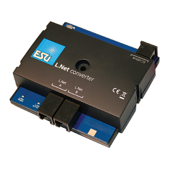
Common (ground) connect. nected to ECoSlink” twice since it fulfils two functions. Figure 2: L.Net converter overview The L.Net converter is wired directly to one of the three ECoS- link sockets of the command station with the supplied ECoSlink cable. -
Page 6: Basic Settings
6.2. Finding an L.Net converter After pressing the “Blinking” button in the configuration dialogue (refer to Fig. 4) the status LED of the L.Net converter will blink rhythmically. This makes finding the module much easier. Alternately you may press the button on the device at any time. -
Page 7: Loconet™ Programming
Once you have called up the module you can read out the address form the LNCV 0. The L.Net converter will then attempt to find the module and to switch it into the programming mode. • Now enter the desired address in the L.Net CV. -
Page 8: Configuration Of Feedback Modules
That way the individual modules can easily be kept apart. This number may be any number between 1 and 1000. When using more than one L.Net converter or in combined ope- ration with ECoSDetectors it is not necessary to assign consecutive numbers. -
Page 9: Administering Several Ecosdetectors
ECoSDetector, the feedback addresses 17 – 32 on the second one, and so forth. You may use feedback information supplied by the L.Net converter in the same manner as is described in the ECoS handbook, chapter 6.5.2. Administering several ECoSDetectors 15. -
Page 10: Dispatching With The Fred® Handheld Throttle
Edisonallee 29 D-89231 Neu-Ulm www.esu.eu Copyright 1998 - 2012 by ESU electronic solutions ulm GmbH & Co KG. Mis- takes, changes resulting in technical advancement, availability and all other rights reserved. Electrical and mechanical characteristics, dimensions and sketches are subject to change without prior notice. ESU may not be held responsible for any... -
Page 11: Warranty Certificate
Extent of warranty / exclusions: This warranty covers the repair or replacement free of charge at the discretion of ESU electronic solutions ulm GmbH & Co. KG of any faulty parts that are caused by design faults or faults in production, material or transport. Any further claims are explicitly excluded. - Page 12 Trouble shooting sheet 1. Customer data (Please write in block letters) Name: ....Street: ....ZIP/City: ....| | | | | | Country: ....Email: ....Phone: ....Date: ..... Signature: ..... 2. Error class Is not detected by the command station Outputs defect No function (error cannot be exactly determined) 3.
Need help?
Do you have a question about the L.Net converter and is the answer not in the manual?
Questions and answers