
Related Manuals for Esu LokPilot V3.0


Summary of Contents for Esu LokPilot V3.0
- Page 1 LokPilot V3.0 User manual 7. edition, November 2009 LokPilot V3.0 LokPilot V3.0 DCC LokPilot V3.0 M4 LokPilot XL V3.0 LokPilot micro V3.0 LokPilot micro V3.0 DCC LokPilot Fx V3.0 LokPilot Fx micro V3.0 P/N 51978...
-
Page 2: Table Of Contents
6.6.4.2. Connecting Universal Motors ....... 16 5.1. The Members of the LokPilot Family ......6 6.7. Connecting Functions ..........16 5.1.1. LokPilot V3.0 Decoders – an Overview ...... 7 6.7.1. Overload Protection of Function Outputs ....16 5.1.2. LokPilot V3.0 ............. 7 6.7.1.1. - Page 3 10.5.2. Märklin® Brake Mode .......... 32 8.1.2. M4 Configuration Range ........24 10.5.3. Selectrix® Diode Brake Sector ......33 8.1.3. M4, the mfx® compatible protocol by ESU ..... 24 10.6. Constant Brake Distance .......... 33 8.2. Programming with popular Digital Systems ....24 10.6.1.
-
Page 4: Declaration Of Conformity 1.Declaration Of Conformity
1.Declaration of conformity 12.3.3.3. Automatic „Coupler“ Function ......39 12.3.4. Blinker lights ............39 We, ESU electronic solutions ulm GmbH & Co KG, Industriestraße 12.3.4.1. Period for Blinker Lights ........39 5, D-89081 Ulm, declare in sole responsibility that the products 12.3.5. -
Page 5: Important Notes - Please R
Only use transformers specifically designed for model trains that bear the VDE/EN marks. Copyright 1998 - 2009 by ESU electronic solutions ulm GmbH & Co KG. Electrical characteristics and dimensions are subject to change without prior notice. All rights reserved. -
Page 6: How This Manual Helps You
In order to suit the different scales and the related current draw in order to be able to adapt your LokPilot decoder optimally to of the model locomotives, all LokPilot V3.0 decoders come in your model locomotive. various options that we now would like to introduce to you. -
Page 7: Lokpilot V3.0 Decoders - An Overview
5.1.4. LokPilot V3.0 M4 The LokPilot V3.0 DCC is a thoroughbred DCC decoder. Except The LokPilot V3.0 M4 is designed for the M4 data format. Besides for the Motorola® and Selectrix® protocol, it supports all the new central units for Märklin systems with the mfx®-data functions of the LokPilot V3.0. -
Page 8: Lokpilot V3.0 Dcc
5.2.1. Operating Modes Motorola® and DCC best suited for the larger scales: It can handle All LokPilot V3.0 decoders (with the exception of the pure DCC a motor current of 3.0A and offers 8 function outputs. Further- decoders) are true multi-protocol decoders with automatic more, dirty tracks finally do not spoil your fun anymore due to detection of the operating mode „on-the-fly.“... -
Page 9: Analogue Mode
Station® and Central Station® all settings are adjusted electronically. Most LokPilot V3.0 decoders support a simple-to- The minimum and maximum speed of the LokPilot V3.0 is use programming procedure. Owners of the ESU ECoS enjoy an adjustable by setting three points or the speed table with 28 even more comfortable method of programming: you can read entries. -
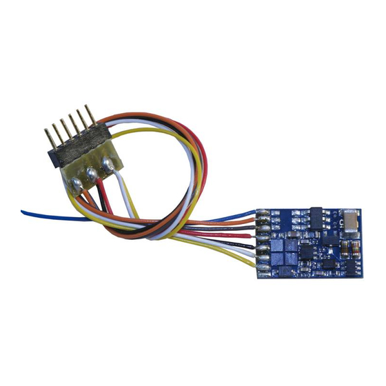
Page 10: Installing The Decoder
(just a little) hot glue. Figure 1: LokPilot V3.0 (DCC/M4), LokPilot Fx V3.0 - NEM652 6.3. Locomotives with 8-pole NEM 652-Interface Some LokPilot V3.0 decoders are supplied with an 8-pole interface •Insert the plug of the decoder in such a way that pin 1 of the... -
Page 11: Locomotives With 6-Pole Nem 651-Interface
6.4. Locomotives with 6-pole NEM 651-Interface place for later use. Some LokPilot V3.0 decoders have a 6-pole NEM 651 plug (as per Fig. 2). Installation in locomotives with this interface is •Insert the plug of the decoder in such a way that pin 1 of the... -
Page 12: Locomotives With 21Mtc Interface
Both the LokPilot V3.0 and the LokPilot V3.0 M4 with the 21MTC •Remove the dummy plug from the socket and keep it in a suitable interface are suitable for controlling the C-Sine control electronics place for later use provided some parameters are set accordingly. -
Page 13: Wiring Diagram For Lokpilot Or Lokpilot Micro
Figure 4: Wiring Diagram for LokPilot V3.0, LokPilot V3.0 DCC, LokPilot V3.0 M4 (examples) motor gray orange black orange 52687 LokPilot micro V3.0 gray 52684 LokPilot micro V3.0 DCC black... -
Page 14: Wiring Diagram For A Lokpilot Xl Decoder
Installing the Decoder 6.6.2. Wiring Diagram for a LokPilot XL Decoder Motor right motor terminal left motor terminal Head Rear Lights Lights Common (+Pole) left track connection right track connection AUX6 AUX5 AUX4 AUX3 AUX2 AUX1 Figure 6: Wiring diagram for LokPilot XL V3.0 (wiring example) gray orange violet... -
Page 15: Colour Coding By Märklin
MUST be removed (also refer to Fig. 9 on the short circuits, particularly between the motor leads and the wheel following page). contacts. Description Märklin color ESU color (following NMRA DCC standard) AC: Power pickup show („Schleifer“) (Center Rail) DC: right track connection AC: Outside Rails brown black... -
Page 16: Connecting Universal Motors
– so called HAMO magnets. You may purchase is too high, the decoder will switch off the outputs. After about these magnets from your ESU dealer. 1 second, the decoder tries to switch them on again. Should the current still be too high –... -
Page 17: Purpose Of Aux3 And Aux4
rating of between 470 Ohms and 2.2 kOhms. Running the LEDs 6.7.3.2. LokPilot Fx V3.0 without this resistor will lead to their destruction! The LokPilot Fx V3.0 offers up to 6 function outputs (also refer to b) The lamps / function outputs are wired (together) against the Fig. -
Page 18: Connecting Capacitors
Disconnect / remove the capacitor prior to programming with the decoder. In this case, you must wire a relay (ESU No. 51963) the ESU LokProgrammer! into the circuit or you slightly reduce the „Brightness“ of the output. -
Page 19: Initial Operation
Initial Operation 7. Initial Operation 52610 LokPilot V3.0 52611 LokPilot V3.0 DCC 7.1. Factory Default Values 61600 LokPilot V3.0 M4 The address is set to 03 with 14 speed steps. LokPilot V3.0 LokPilot V3.0 DCC LokPilot V3.0 M4 LokPilot micro V3.0 LokPilot micro V3.0 DCC... -
Page 20: Digital Operating Modes
• ROCO® Lokmaus2 and Lokmaus3 • Uhlenbrock® Intellibox 7.2.1. DCC Mode • Lenz® Digital plus V2.3 LokPilot V3.0 LokPilot V3.0 DCC • ZIMO® MX1 LokPilot micro V3.0 LokPilot micro V3.0 DCC When operating with Lenz® digital plus V3.0 the auto-detect LokPilot XL V3.0... -
Page 21: Motorola® Mode
Station®, only supports 14 speed steps, the LokPilot decoder the decoder detects a power interruption. can also handle the 28-speed step mode. In conjunction with suitable command stations (e.g.: ESU ECoS, in „Motorola® 28“ 7.2.4. M4 Mode mode) this leads to smoother control of your locomotives. No LokPilot V3.0 M4... -
Page 22: Analogue Mode
Nevertheless, there are plenty of possibilities to influence the the old directional relay. Load compensation is active (similar to behaviour of the LokPilot decoder by adjusting software-governed DC mode) and provides smooth control and slow-speed- properties. performance you have never seen before. The LokPilot V3.0... -
Page 23: Configuration Variables (Cvs)
8.1.1. Configuration Variables (CVs) „Value“ has two numbers for each option. If the option is switched off, the value is 0. Otherwise, it is a number between 1 LokPilot V3.0 LokPilot V3.0 DCC and 128. LokPilot micro V3.0 LokPilot micro V3.0 DCC Add all the values for the respective options to arrive at the correct LokPilot XL V3.0... -
Page 24: M4 Configuration Range
M4 capable disadvantages: On the one hand dealing with „collection CVs“ command station or with the ESU LokProgrammer. Any settings such as CV 29 with its binary format is complicated while on the programmed there are also valid when operating the decoder other hand you can only enter one value (!). -
Page 25: Programming With The Esu Ecos
Each decoder receiving this command will execute it. start a special, obligatory programming procedure. Reading of ESU counts the bits from 0 to 7 as laid out in the standards while values is not permitted. others (e.g.: Lenz) count the bits from 1 to 8. Please bear this in... -
Page 26: Changing The Programming Mode
The LokPilot XL V3.0 is capable of handling both the short and again (press the „Stop“ button on the 6021, then the „Go“ the long mode. LokPilot V3.0 decoders starting with software button). version 0.0.6560 support the long mode. The LokPilot micro V3.0 8.2.3.3. -
Page 27: Programming With The Märklin® Central Station
•The Mobile Station® will program the new value into the decoder. 8.2.4. Programming with the Märklin® Mobile Station® LokPilot V3.0 M4 Please remove all other locomotives prior to programming! 8.2.5. Programming with the Märklin® Central Station LokPilot V3.0 M4 Like any other M4 decoder, the LokPilot M4 reports automatically to the Mobile Station®... -
Page 28: Programming With The Esu Lokprogrammer
LokProgrammer. decoder can only respond to one address at a time. You can access all properties of ESU decoders with the If you want to use your LokPilot with the long address it is practical LokProgrammer. Since this works independently form the data to program this address directly with your digital system: most format it also works for M4 decoders. -
Page 29: Motorola® Address
The LokPilot M4 accepts values from 1 to 255 in CV 1. With the longer is the distance until it stops. suitable command stations such as the ESU ECoS, you have about three times as many addresses available compared to the origi- For information on how to set a brake distance independently of nal Märklin®... -
Page 30: Shunting Mode
This mode is only active if bit 4 in CV 29 is set. Motor characteristic via CV 2, 5, and 6 (Fig. 12): enter the start We recommend using the ESU LokProgrammer for easy and voltage in CV 2 and the maximum speed in CV 5. CV 6 comfortable programming. -
Page 31: Changing Between Operating Modes
Each M4 decoder has its own speed curve. However, it is only accessible with an M4 capable central unit or with the ESU Does the direction not match the commands from the digital LokProgrammer. -
Page 32: Changing Modes With Analogue Mode Turned Off
(also refer to chapter 7.2.3). per the programmed values in CV 3. LokPilot V3.0 M4 Depending on the type of digital system, there are several options on how to influence the decoder so that it stops the train. -
Page 33: Selectrix® Diode Brake Sector
An attractive function hides behind CV 254 (ESU brake mode): Here you can set a constant distance for braking the train, from the beginning of the brake sector to the stopping point. Thus, it... -
Page 34: Dc Analogue Operation
4th generation load compensation enables LokPilot decoders to execute precise motor control. Even with the default settings, Please note that (with the exception of the LokPilot V3.0 M4) most locomotives run perfectly. load compensation is always active ex works, even in analogue mode. -
Page 35: Adjustments For Other Motors / „Fine Tuning
Motor Control 11.1.2. Adjustments for other Motors / „Fine Tuning“ 11.1.2.1. Parameter „K“ Unfortunately, the motors available in the market have Parameter „K“, stored in CV 54, influences how strongly load considerable variations due to tolerances. This is even true for control will affect the driving performance. -
Page 36: Parameter „I
11.1.2.2. Parameter „I“ 11.2. Turning off Load Compensation Parameter „I“, stored in CV 55 provides important information LokPilot V3.0 LokPilot V3.0 DCC to the decoder on how much inertia the motor has. Motors with LokPilot micro V3.0 LokPilot micro V3.0 DCC large flywheels naturally have more inertia than smaller ones or coreless motors. -
Page 37: Dynamic Drive Control: Up And Down The Hill
LokPilot V3.0 11.4. Dynamic Drive Control: Up and Down the Hill LokPilot V3.0 LokPilot V3.0 DCC LokPilot V3.0 M4 LokPilot micro V3.0 LokPilot micro V3.0 DCC LokPilot XL V3.0 Write the values below into the respective CVs: V V V V V alue... -
Page 38: Function Outputs
LokPilot Fx V3.0 LokPilot Fx micro V3.0 • Strobe: flash light. You can allocate the functions freely to any function button. ESU • Double Strobe: double flash light. uses the so-called extended „Mapping“. It has the advantage • Firebox: flickering light simulating the open firebox. -
Page 39: Adjust Lamp Brightness
12.3.3.3. Automatic Coupler Function nal voltage! It is essential that you refer to chapter 6.7.1.1 for more details! LokPilot V3.0 LokPilot V3.0 DCC LokPilot XL V3.0 12.3.3. Digital Couplers LokPilot V3.0 LokPilot V3.0 DCC From firmware version 0.0.6520 on the LokPilot decoder is able... - Page 40 Figure 13: Function mapping - factory default values for LokPilot V3.0 Funct.- Description Control Headlight Back-up lights AUX 1 AUX 2 AUX 3 AUX 4 AUX 5 AUX 6 button CV A (if available) (if available) (if available) (if available)
- Page 41 Funct.- Control Acceleration Shunting „Sound“ Dynamic Button CV B ON/OFF mode On/Off On / Off brake FS(f) FS(r) FF(f) FF(r)
-
Page 42: Blinker Lights
Function Outputs In CV 247 the time of pushing is to be entered. function is programmed for forward travel. Now enter the same values in CV 174 in order to activate the same for travelling in In CV248 the time of removing is to be entered. reverse. -
Page 43: Analogue Settings
12.4. Analogue Settings Figure 18 shows one option of how to wire this arrangement LokPilot V3.0 LokPilot V3.0 DCC LokPilot V3.0 M4 with AUX1 (green wire) being used for the third circuit. All you LokPilot micro V3.0 LokPilot micro V3.0 DCC... -
Page 44: Special Functions
Special Functions is actually only intended for operation with the 6020 since the 13.3. With the ESU LokProgrammer 6020 does not transmit any commands after being switched on. Enter the value 08 in CV 08 in the option „Read / Write CVs“ in The default setting records the direction, the status of the the menue „Edit CVs“. -
Page 45: Railcom
You can carry out the update yourself without having to remove LokPilot micro V3.0 LokPilot micro V3.0 DCC the decoder from the locomotive. All you need is the ESU LokPilot XL V3.0 LokProgrammer. The most recent version of the firmware can be downloaded free of charge from our website. -
Page 46: Accessories
LokPilot decoder. Firstly, you must replace the other users that may help you with your particular question. stator coil with a permanent magnet. ESU supplies the following magnets: Of course we will always assist you; please contact us at:... -
Page 47: T 20. Technical Data Echnical Data Echnical Data
20. Technical Data LokPilot micro LokPilot micro LokPilot V3.0 LokPilot V3.0 LokPilot V3.0 LokPilot XL LokPilot Fx LokPilot Fx V3.0 V3.0 DCC V3.0 V3.0 micro V3.0 Operation Voltage 5 – 25V 5 – 25V 5 – 40V 5 – 27V 5 –... -
Page 48: List Of All Supported Cvs
LokPilot not to respond at all. CV Name Description Range Def. primary address Address of engine (For LokPilot V3.0, LokPilot XL V3.0: Ragne = 1 - 255) 1 – 127 Start voltage* Sets the minimum speed of the engine 1 – 75 Acceleration This value multiplied by 0.869 is the time from stop to... - Page 49 Name Description Range Def. Analogue mode FL, Status of function FL, F9 to F12 in analogue mode 0-255 F9-F12 Bit Function value Function FL(f) Function FL(r) Function F9(f) Function F10 (f) Function F11 Function F12 Function F9(r) Function F10 (r) Extended engine address long addrss of engine 128.-...
- Page 50 List of all supported CVs Name Description Range Value Consist Mode FL, F9-F12 Status of fucntions FL, F9 to F12 in Consist mode 0-255 Bit Function Value Function FL(f) Function FL(r) Function F9(f) Function F10(f) Function F11 Function F12 Function F9(r) Function F10(r) RailCom Configuration Settings for RailCom...
- Page 51 Name Description Range Value Configuration register The most complex CV within the DCC standards. This register contains important information, some of which are only relevant for DCC operation Bit Function Value Reverse direction of travel (forward becomes reverse) Normal direction Reversed direction Speed steps (For DCC-opearation only) 14 speed steps...
- Page 52 List of all supported CVs Name Description Range Value Extended Additional important settings for LokPilot Decoders 0 - 255 Configuration Bit Description Value Enable Load control (Back-EMF) (not for LokPilot Fx V3.0) Disable Load control (Back-EMF) Motor PWM frequency 16 kHz motor pulse frequency 32 kHz motor pulse frequency Märklin Delta Mode Disable Märklin Delta Mode (Headlights controlled by command station) 0...
- Page 53 Name Description Range Value Analogue mode Selection of allowed analogue modes Bit Function Value AC Analogue Mode (if implemented. Please refer to section 7.3.) Disable AC Analog Mode Enable AC Analog Mode DC Analogue mode Disable DC Analogue mode Enable DC Analogue Mode Brake modes Selection of desired (allowed) brake modes Bit Function...
- Page 54 List of all supported CVs Name Description Range Value Operating range of load control 0 – 100 % 1 - 64 (not for LokPilot Fx) Defines up to which speed in % load control will be active. A value of 32 indicates that load control will be effective up to half speed.
- Page 55 Name Description Range Value 114 Back-up light Configuration of back-up lights 0 - 255 configuration Description Value continuous (dimmer) blinking (Phase 1) Vol + 16 blinking (Phase 2) Vol + 32 Strobe light Vol + 48 Double Strobe light Vol + 64 Fire box Vol + 80 Smoke generator...
- Page 56 List of all supported CVs Name Description Range Value 116 AUX 2 configuration Configuration of output „AUX 2“ 0 - 255 Description Value continuous (dimmer) blinking (Phase 1) Vol + 16 blinking (Phase 2) Vol + 32 Strobe light Vol + 48 Double Strobe light Vol + 64 Fire box...
- Page 57 Name Description Range Value 118 AUX 4 configuration Configuration of output „AUX 4“ 0 - 255 (21MTC Version only) Description Value (LokPilot Fx V3.0) continuous (dimmer) (LokPilot XL V3.0) blinking (Phase 1) Vol + 16 blinking (Phase 2) Vol + 32 Strobe light Vol + 48 Double Strobe light...
- Page 58 List of all supported CVs Name Description Range Value 120 AUX 6 configuration Configuration of output „AUX 6“ 0 - 255 (LokPilot XL only) Description Value continuous (dimmer) blinking (Phase 1) Vol + 16 blinking (Phase 2) Vol + 32 Strobe light Vol + 48 Double Strobe light...
- Page 59 Name Description Range Value 129 Assignment of function button Assignment of function outputs that are activated in status „stop-forward“ 0 – 255 „Stop“ Forward A Bit Description Value headlights back-up lights function output AUX 1 function output AUX 2 function output AUX 3 (if available) function output AUX 4 (if available) function output AUX 5 (if available) function output AUX 6 (if available)
- Page 60 List of all supported CVs CV Name Description Range Value 135 Assignment of function button Assignment of function outputs that are activated in status „running-forward“ 0 - 255 „Running“ forward A Bit Description Value headlights back-up lights function output AUX 1 function output AUX 2 function output AUX 3 (if available) function output AUX 4 (if available)
- Page 61 Name Description Range Value 141 Assignment of function button Assignment of function outputs that are activated in status „headlight-forward“ 0 - 255 headlight forward A Bit Description Value headlights back-up lights function output AUX 1 function output AUX 2 function output AUX 3 (if available) function output AUX 4 (if available) function output AUX 5 (if available) function output AUX 6 (if available)
- Page 62 List of all supported CVs Name Description Range Value 147 Assignment of function button Assignment of function outputs that are activated in status „F1- forward“ 0 - 255 F1 Forward A Bit Description Value headlights back-up lights function output AUX 1 function output AUX 2 function output AUX 3 (if available) function output AUX 4 (if available)
- Page 63 Name Description Range Value 153 Assignment of function button Assignment of function outputs that are activated in status „F2 - forward“ 0 - 255 F2 forward A refer to CV 129 154 Assignment of function button Assignment of function outputs that are activated in status „F2 - forward“ 0 - 255 F2 forward B refer to CV 130...
- Page 64 List of all supported CVs Name Description Range Value 172 Assignment of function button Assignment of function outputs that are activated in status „F5 - forward“ 0 - 255 F5 Forward B refer to CV 130 174 Assignment of function button Assignment of function outputs that are activated in status „F5 - reverse“ 0 - 255 F5 Reverse A refer to CV 129...
- Page 65 Name Description Range Value 192 Assignment of function button Assignment of function outputs that are activated in status „F8 - reverse“ 0 - 255 F8 Reverse A refer to CV 129 193 Assignment of function button Assignment of function outputs that are activated in status „F8 - reverse“ 0 - 255 F8 Reverse B refer to CV 130...
- Page 66 List of all supported CVs Name Description Range Value 211 Assignment of function button Assignment of function outputs that are activated in status „F11 - reverse“ 0 - 255 F11 Reverse B refer to CV 130 213 Assignment of function button Assignment of function outputs that are activated in status „F12 - forward“ 0 - 255 F12 Forward A refer to CV 129...
- Page 67 Name Description Range Value 231 Assignment of function button Assignment of function outputs that are activated in status „F15 - forward“ 0 - 255 F15 Forward A refer to CV 129 232 Assignment of function button Assignment of function outputs that are activated in status „F15 - forward“ 0 - 255 F15 Forward B refer to CV 130...
-
Page 68: M4-Decoder
Value settings, which can be reached via Motorola programming. Important: All values have to be multiplied by „ 4“, if used together with a Central Station or the ESU LokProgrammer, as a value setting of 0 - 255 is adequate!!! - Page 69 For your personal notes:...
-
Page 70: Appendix
Appendix 22. Appendix If you wish to read out your addresses, please read out CV17 and CV18 one after another and flip the process: Let´s say you read out the following: 22.1. How to programm long addresses CV17 = 196; CV 18 = 147. For the corresponding address section As described in chapter 9.2., the long address is separated into look on fig. -
Page 71: Arranty
4. In case of inappropriate use (different to the intended use as specified by the manufacturer). 5. If the instructions as laid down in the user manual by ESU electronic solutions ulm GmbH & Co. KG were not adhere to. - Page 72 Trouble Shooting Sheet 1. Personal information (Please use block letters) Name: ....Street: ....ZIP code/ city: ..| | | | | | Country: ....Email: ....Telephone: ... Date: ....Signature: .... 2. Product details and system enviroment Art.No.: Date of purchase: Address :...
Need help?
Do you have a question about the LokPilot V3.0 and is the answer not in the manual?
Questions and answers