Table of Contents
Advertisement
Advertisement
Table of Contents

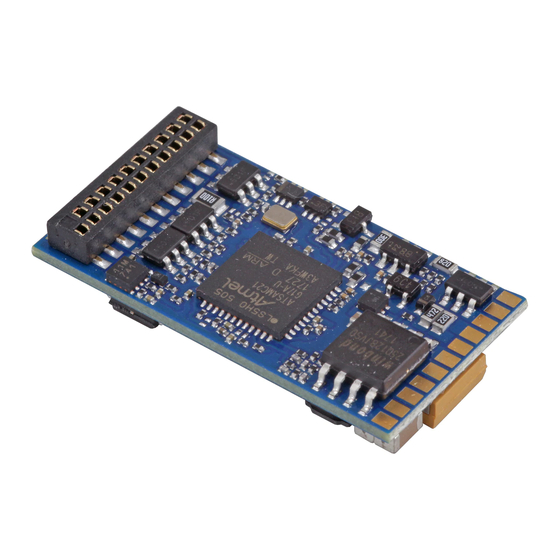
Summary of Contents for Esu LokSound 5 DCC
- Page 1 LokSound 5 DCC Instruction manual GHB «DD-1» P/N 99440...
-
Page 2: Table Of Contents
3.1.6. Programming with the ESU LokProgrammer ....6 3.4. Setting up your LokSound ..........6 3.4.1. Address Settings ............6 Copyright 1998 - 2020 by ESU electronic solutions ulm GmbH & Co KG. Electri- 3.4.1.1. Primary Address .............6 cal characteristics and dimensions are subject to change without prior notice. -
Page 3: Introduction
1.1. Properties of the decoder The “DD-1” can be operated straight out of the box. The appro- The LokSound 5 DCC decoder by ESU is a versatile digital decoder priate operating mode is selected automatically. You do not have integrating a full-featured, 10 channel sound system, various to change any parameters. -
Page 4: Initial Operation
Initial operation 2.1. Function mapping The default address assigned to the LokSound decoder is 3. Sim- ply set your controller to this locomotive number and place it on Button Function the mainline. If everything is set up properly, the “DD-1” should Directional Headlights react as shown on the table 2.1. -
Page 5: Decoder Settings
CVs (adherence is website www.esu.eu obligatory). This greatly simplifies things for the user since decod- ers of most manufacturers comply with this standard and there- 3.1. -
Page 6: Programming On The Main
You can access all properties of ESU decoders with the LokPro- its locomotive address, for instance: grammer. You even can erase the sound and download a new “Locomotive number 50, write the value 7 into CV 3!“. -
Page 7: Extended Address
Both the primary and the extended address may be changed at formance. any time using service mode (on the programming track). Some DCC systems (such as ESU ECoS, ESU Navigator) will allow 3.4.2.3. Shunting mode the decoder address to be modified using Programming On The The shunting mode reduces the speed to about 50%. -
Page 8: Dc Brake Mode
Decoder settings 3.4.3.1. DC Brake Mode Before you change any of the volume control CVs, please make sure that the CV 31 is set to 16 and CV 32 = 1! In order to activate the DC brake mode you must set bit 3 in CV 27. -
Page 9: Appendix
Appendix 5. Appendix 5.1.2. Read out addess If you wish to read out the address of a locomotive please read the values of CV 17 and CV 18 one after another and proceed 5.1. Programming Long Addresses then in reverse order: As described in chapter 3.3.1.2. - Page 10 Programming table - List of most important CVs Name Description Range Default Locomotive address DCC/Motorola® address of locomotive 1 - 127 Start voltage Sets the minimum speed of the locomotive 0 - 255 Acceleration This value multiplied by 0.25 is the time from stop to maximum speed. 0 - 255 Deceleration This value multiplied by 0.25 is the time from maximum speed to stop.
- Page 11 Enable analog operation Disable RailCom® Enable RailCom® Motor characteristic through CV 2, 6, 5 (For LokSound 5 DCC only!) Motor characteristic through CV 67 - 94 (always active on LokSound 5) Short addresses (CV 1) in DCC mode Long addresses (CV 17 + 18) in DCC mode...
- Page 12 Programming table - List of most important CVs Name Description Range Default Extended Configuration #1 Additional important settings for LokSound Decoders 0 - 255 Description Value Enable Load control Disable Load control reserved Reserved Reserved Automatic DCC speed step detection Disable DCC speed step detection Enable DCC speed step detection LGB®...
- Page 13 Programming table - List of most important CVs Name Description Range Default Sound volume Master volume control for all sounds. 0 - 192 Brake sound threshold «Brake On» If the actual loco speed step is smaller than or equals the value indicated here, the brake 0 - 255 sound is triggered.
- Page 14 Programming table - List of most important CVs Name Description Range Default ABC-Mode „Sensibility” Threshold, from which asymmentry on ABC shall be recognised. 4 - 32 Notch Points Notch Point 1 - Notch Point 8: The internal speed step where the diesel engine sound 0 - 255 -162 notches to the next Notch (Not for all sound projects)
-
Page 15: Support And Assistance
++49 (0) 731 - 1 84 78 - 106 Tuesday & Wednesday 10:00am - 12:00am Fax: ++49 (0) 731 - 1 84 78 - 299 Email: www.esu.eu/en/forum Mail: ESU GmbH & Co. KG - Technischer Support - Edisonallee 29 D-89231 Neu-Ulm www.esu.eu... - Page 16 Instruction manual - LokSound 5 - GHB „DD-1“...


Need help?
Do you have a question about the LokSound 5 DCC and is the answer not in the manual?
Questions and answers
what is the CV for momentum?
The CV for momentum in ESU 5 DCC is CV 4.
This answer is automatically generated