
Subscribe to Our Youtube Channel
Related Manuals for Esu SignalPilot 51840


Summary of Contents for Esu SignalPilot 51840
- Page 1 SignalPilot Instruction manual 1 . E d i t i o n , J a n u a r y 2 0 2 1 From decoder firmware 1.0.4 51840 SignalPilot P/N 00321-24476...
-
Page 2: Table Of Contents
Content 1. Declaration of Conformity ........4 6.8.1. Signal name .............16 6.8.2. Turnout numbers and signal aspects ......16 2. WEEE Declaration............. 4 6.8.3. Changing turnout numbers ........19 6.8.4. Assign outputs ............19 3. Important Notes ............4 6.8.5. Switch all outputs to GND ........20 6.9. - Page 3 Alle anderen Warenzeichen sind Eigentum ihrer jeweiligen Rechteinhaber. ESU electronic solutions ulm GmbH & Co. KG entwickelt entsprechend seiner Politik die Produkte ständig weiter. ESU behält sich deshalb das Recht vor, ohne vorherige Ankündigung an jedem der in der Dokumentation beschriebenen Produkte Änderungen und Verbesserungen vorzunehmen.
-
Page 4: Declaration Of Conformity
Declaration of Conformity 1. Declaration of Conformity 3. Important Notes The manufacturer, ESU electronic solutions ulm GmbH & Co. KG, Congratulations on your purchase of an ESU SignalPilot decoder. Edisonallee 29, D-89231 Neu-Ulm, hereby declares under its sole This manual wants to introduce you step by step to the possibilities responsibility that the product of the decoder. -
Page 5: Features
All signal aspects predefined in the LokProgrammer software can be changed individually. The description of the signal aspects themselves is done with the help of XML files, which on the one hand are regularly extended by ESU or can be created and exten-... -
Page 6: Technical Data
Up to 16 turnout numbers (SANs) for signal aspects. Separate turnout number for global blanking. Separate turnout number (address) for POM programming. Configuration With ESU LokProgrammer and LokProgrammer software Dimensions 86mm x 86mm x 25mm 4.3. Scope of delivery The SignalPilot is supplied with 5 removable terminal blocks (1x... -
Page 7: Connection To The Digital System
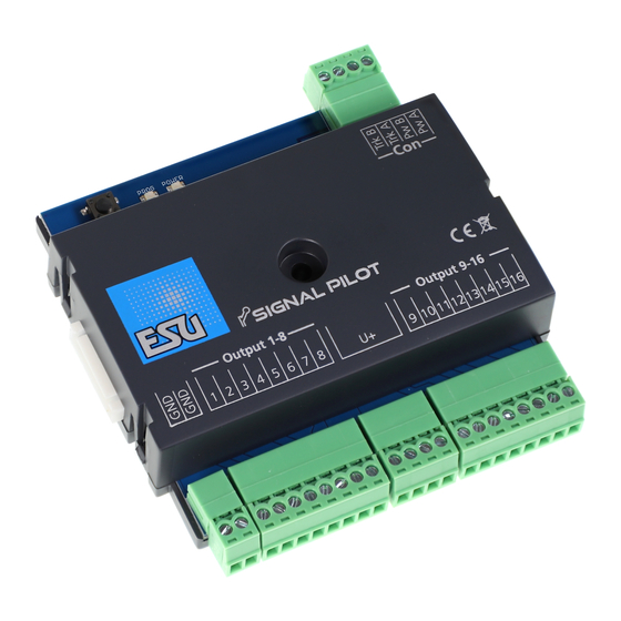
Connection to the digital system 5. Connection to the digital system We recommend that you first configure the SignalPilot decoder completely and only then install it in the layout. 5.1. Terminals Fig. 1 shows the SignalPilot with all terminals. a) Daylight signals, motorised turnout-drives or similar loads shall be connected to the terminals labelled 1 to 16 for outputs 1 to 16. -
Page 8: Power Supply From The Digital System
Trk A and Trk B. mend the use of a stabilized DC power supply with at least 18V DC and at least 3A output power (e.g.: ESU part number 50119). This type of wiring must be used if you want to configure the SignalPilot on the programming track of your command station. -
Page 9: Wiring The Outputs
Wiring the outputs 5.4. Wiring the outputs 5.4.2. Daylight signals with LEDs, common anode Consumer loads can be connected to the SignalPilot very flexibly. Most daylight signals available on the market are equipped with However, it is important that in addition to the correct terminal, LEDs with common anode (e.g.: Busch). -
Page 10: Daylight Signals With Leds, Common Cathode
Wiring the outputs 5.4.3. Daylight signals with LEDs, common cathode For some daylight signals (especially those by Viessmann®) the minus poles („Cathode”) of the individual LEDs are connected. These must be wired to a negative potential („GND”). The plus pole of the single LEDs („Anode”) is connected to the respective output, as shown in Fig. -
Page 11: Connecting The Switchpilot Extension
Connecting the SwitchPilot Extension 5.5. Connecting the SwitchPilot Extension 5.5.2. Turnout frog polarisation The SwitchPilot Extension module is docked to the SignalPilot at Turnout frogs can be polarized very easily with the SwitchPilot the side; push the two modules with the 8-pin plug/socket con- Extension. -
Page 12: Abc Brake Sector
Connecting the SwitchPilot Extension 5.5.3. ABC Brake sector An ABC brake sector can also be activated, if so desired. The ABC brake sector adapter 51808 is required for this purpose. The wi- ring is shown in Fig. 8. Refer to the operating instructions of the 51808 ABC brake sector adapter to learn more about the system requirements of the ABC braking technique. -
Page 13: Configuration With Lokprogrammer
Configuration with LokProgrammer 6. Configuration with LokProgrammer After the configuration has been transferred to the SignalPilot, it can no longer be read out. For processing, therefore, the saved The SignalPilot must be configured with the LokProgrammer and project file (in the „.esux” format) is required. the appropriate software. -
Page 14: Basic Address
Configuration with LokProgrammer 6.3.1. Basic address 6.4. „Signals” register • Click on the „Decoder” icon on the left column. As a second step, No further relevant settings can be made in the „Decoder” regis- select the Address group from the centre column. ter. -
Page 15: Night Service Extension
Configuration with LokProgrammer • If no item is selected, the detail box is empty. 6.4.2. Random Operation Settings • If the SignalPilot itself is marked (clicked), the detail area displays Lights can also be switched on and off randomly, if so desired. the setting options of the SignalPilot itself (see 6.4.1 or 6.4.2). -
Page 16: Moving Signals
Moving Signals In this way, you can connect as many signals as you want to the 6.8. Configuring Signals SignalPilot. The properties of each placed signal can be changed after it has If there are not enough free function outputs for the desired sig- been selected. - Page 17 Configuring signals Example 1: 2-aspect block signal If you hover the mouse on one of the signal images, you will see which lights are turned on: In our first example, the signal displays the signal aspects „Hp0” for „Stop” and „Hp1” for „Proceed”. One turnout number is suf- ficient to represent these two signal aspects.
- Page 18 Turnout numbers and signal aspects Example 2: 3 aspect H/V exit signal If you hover the mouse on one of the signal images, you will see which lights will be on: To switch the two signal aspects, the „red” or „green” buttons of the corresponding turnout number must now be pressed at the turnout console: a) The signal aspect „Hp0”...
-
Page 19: Changing Turnout Numbers
The turnout numbers do not have to be continuous, but we recommend this, as most digital command stations (e.g.: ESU ECoS) assume this. • Release the mouse. The output is automatically connected to the new position. -
Page 20: Switch All Outputs To Gnd
Switch all outputs to GND 6.8.5. Switch all outputs to GND If you use Viessmann signals, all outputs used must receive the „Pull” configuration. This is done quickly but may not be over- looked. • Select the signal so that the detail area shows the signal proper- ties. -
Page 21: Switch Output To Gnd
Switch output to GND 6.9.1. Switch output to GND 6.9.3. Fade-in and fade-out times Here, the „Pull” configuration of the output can be activated if Every light can be faded-in and -out if so desired. The change-over this is not to be done simultaneously for all outputs of the signal. time can be set with the two sliders. -
Page 22: Assign Spe Relays
Assign SPE relays 6.9.5. Assign SPE relays You cannot define which signal aspect uses the basic or alternative output configuration with the LokProgrammer software. This is set Each active output can control one of the four relays of a connec- when defining the signal aspect. -
Page 23: Wiring The Signalpilot
Wiring the SignalPilot 6.12. Wiring the SignalPilot We recommend that you first establish the wiring with the sig- nals, test the functions and only then install the SignalPilot on the layout. 6.12.1. Save the wiring diagram To make it easier for you to install the wiring, you can save the work area as an image and print it out, if desired. -
Page 24: Signal Aspects And Assignment To Turnout Numbers
To understand Signal aspects 6.13.2. Signal aspects and the assignment to turnout numbers The exit signal requires turnout numbers seven and eight. „RED” (7) turns on Hp0, „GREEN” (7) turns on Hp1, „GREEN” (8) turns As already shown in the examples in chapter 6.8.2., the turnout on the yellow light for Hp2. -
Page 25: Blanking
Distant signals All this is possible with the SignalPilot. Let’s have a look at an ex- 6.14.1. Blanking ample of how this can be accomplished. Now the distant signal must be configured to be blanked (dark) if the main signal on the SAME MAST(!) displays Hp0. To do this, we first configure the distant signal for block 2. - Page 26 Distant signals This setting corresponds to the main signal on the same mast. Do not enter the turnout number of the main signal here, but its SAN (Signal Address Number). The currently set turnout number for the corresponding SAN is displayed on the right for your in- formation.
-
Page 27: Pom Configuration (Programming On The Main)
POM configuration 7. POM Configuration (Programming on the Main) • Go to the ECoS main menu. • Select “Programming on the Main” (POM), “DCC” and “Accesso- The SignalPilot may remain installed on your layout during pro- ry decoder”. gramming. For POM to work, your digital system must support •... -
Page 28: Configuration Via Programming Track
Configuration via programming track 8. Configuration via programming track 10. RailCom® In some cases, it may be desirable to change the properties of the RailCom® is a technique for transferring information from the de- SignalPilot via the programming track. There, the CVs can not only coder back to the command station. -
Page 29: User-Defined Signals
The signal aspects directory can be entered or selected there: ESU will continuously expand the number of signal aspects. Howe- ver, you do not necessarily have to wait for ESU to enter your desi- red signal type: With a little patience and practice you will be able to define your own signals. -
Page 30: Support
10.00 to 12.00 o‘ clock by Fax : +49 (0) 731 - 1 84 78 - 299 by E-Mail: www.esu.eu/kontakt by mail: ESU GmbH & Co. KG Edisonallee 29 D-89231 Neu-Ulm www.esu.eu For USA, Canada, Australia by phone: +1 570-980-1982 Tuesday &... -
Page 31: Warranty Certificate
Therefore ESU electronic solutions ulm GmbH & Co. KG grants you a warranty for the purchase of ESU products that far exceeds the national warranty as governed by legislation in your country and beyond the warranty from your authorised ESU dealer. - Page 32 Trouble shooting sheet 1. Personal data (Please write in BLOCK LETTERS) Name: ....Street: ....ZIP/City: ....| | | | | | Country: ....Email: ....Phone: ....Date: ..... Signature: ..... 2. Error Transistor outputs Short circuit Servo outputs No function from the start No Function Programming on the Main...
Need help?
Do you have a question about the SignalPilot 51840 and is the answer not in the manual?
Questions and answers