Table of Contents
Advertisement
Quick Links
Download this manual
See also:
User Manual
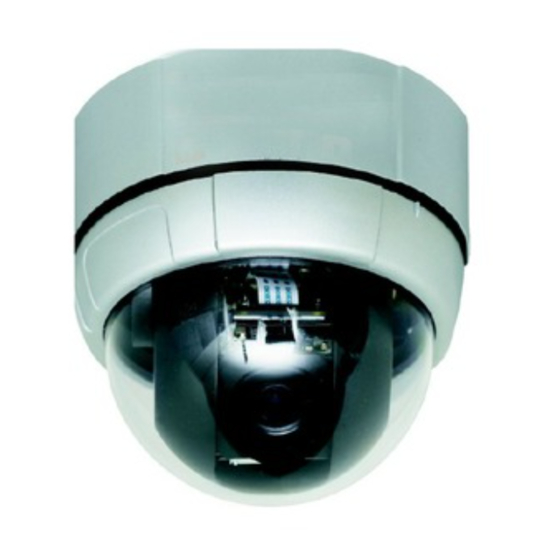
3.8-38 mm 10X motorized day/night dome colour camera
430 521
3.5-94.5 mm 27X motorized day/night dome colour camera
430 522
3.8-38 mm 10X weatherproof motorized day/night dome colour
camera
430 523
3.5-94.5 mm 27X weatherproof motorized day/night dome colour
camera
430 524
3.5-129.5 mm 37X weatherproof motorized day/night dome colour
camera
430 525
430 521
430 523
Instructions manual
430 522
430 524/525
Advertisement
Table of Contents

Related Manuals for LEGRAND 430 521


Summary of Contents for LEGRAND 430 521
- Page 1 3.8-38 mm 10X motorized day/night dome colour camera 430 521 3.5-94.5 mm 27X motorized day/night dome colour camera 430 522 3.8-38 mm 10X weatherproof motorized day/night dome colour camera 430 523 3.5-94.5 mm 27X weatherproof motorized day/night dome colour camera 430 524 3.5-129.5 mm 37X weatherproof motorized day/night dome colour...
- Page 2 _________________________________________________________________________________ IMPORTANT SAFETY GUIDE Read, heed and follow all the Instructions Read all the safety and operating instructions before using the product. Keep this manual Keep this manual for reference in future. Attachments / Accessories Use only the attachments or accessories specified by the manufacturer. Installation ...
- Page 3 _________________________________________________________________________________ CAUTION Operating Before using, make sure that the power supply and others are properly installed. While operating, if any abnormal condition or malfunction is observed, stop using the product immediately and then contact your local dealer. Handling ...
-
Page 4: Table Of Contents
_________________________________________________________________________________ TABLE OF CONTENTS Introduction Model Code Features Package Components Main Part Description Installation DIP Switch Setup In-Ceiling Mount Installation (MPS) Installation with Surface Mount Bracket (MPS) Direct Installation on the Ceiling Mount Bracket(MPS) Installation using Wall Mount Bracket(MPS) Installation with Ceiling Mount Bracket(MAO/MAI) Installation with Wall Mount Bracket(MAO/MAI) Wiring and Cabling Operation... -
Page 5: Introduction
_________________________________________________________________________________ 1. INTRODUCTION MODEL CODE Ref. 430 521 430 522 430 523 430 524 430 525 Mini Mini Mini Aluminium Aluminium plastic Aluminium Aluminium Serie with with small with with fan/heater fan/heater fan/heater fan/heater Outdoor serie Video signal Wall mount... -
Page 6: Features
_________________________________________________________________________________ 1.2. FEATURES Powerful Zoom Camera & Setup Options 430 521 430 522 430 523 430 524 430 524 Optical Zoom Digital Zoom Max. zoom x100 x324 x444 magnification High light compensation Privacy Masks Day & Night Focus Mode Auto-Focus, Manual Focus, Semi-Auto Focus... - Page 7 Alarm In/Out Function 430 522 : 4 alarm sensor inputs and 2 alarm output relays 430 521/430 523/430 524/430 525 : 3 alarm sensor inputs and 1 alarm sensor outputs Alarm sensor input is decoupled with photo-couplers to avoid external electric noise and shock perfectly.
- Page 8 _________________________________________________________________________________ Alarm ” function is possible, which is supposed to activate after user-defined time period and sequentially in succession to the action by external sensor activations. Reserved Presets (Hot Keys) Most camera setup options can be set up easily and directly with the reserved presets (Hot Keys), without entering into OSD menu.
-
Page 9: Package Components
_________________________________________________________________________________ 1.3. Package Component (430 521 Model) Product & Accessories Main Body & Surface Mount Bracket Default Accessories [Main Cable, Calblock, Screws : Tapping M4 16, Tapping M4 25, Machine M3 6, Machine M3 8] I/O Cable... - Page 10 _________________________________________________________________________________ Package Component (430 522 Model) Product & Accessories Main Body / Terminal Cover Dome Cover Screws Optional brackets In-Ceiling Mount Bracket Ceiling Mount Bracket Corner bracket Wall mount bracket 430 596 430 597 430 598 430 594...
- Page 11 Package Component (430 523/430 524/430 525 Models) Product & Accessories Default Accessories Main Body & Surface Mount Bracket [Main Cable, Wrench] Accessories for The Models with Alarm Wall Mount Bracket In/Out Function [I/O Cable] [Screws : Machine M5 15, Hex Lag #14 50] Optional Brackets Corner bracket 430 598 Ceiling Mount Bracket 430 595...
- Page 12 _________________________________________________________________________________ 1.4. Main Part Description (430 521 Model) Do not detach the protection vinyl from the dome cover Dome Cover before finishing all the installation process to protect the dome cover from scratches or dust. Used to lock up the dome cover after assembling the dome ...
- Page 13 Main Part Description (430 522 Model) Do not detach protection vinyl from dome cover before Dome Cover finishing all installation process to protect dome cover from scratches or dust This is used to install the camera directly on the ...
- Page 14 _________________________________________________________________________________ I/O cables are connected on to this cabling terminal Block block.
-
Page 15: Main Part Description
Main Part Description (430 523 Model) Mounting Screw Hole Mounting Hook DIP Switch Main Connector Sensor I/O Port Dome Cover Main Body / Terminal Cover Do not detach the protection vinyl from the dome cover Dome Cover before finishing all the installation process to protect the dome cover from scratches or dust. - Page 16 _________________________________________________________________________________ Terminal Cover Disassembling ① Remove the Lockup Screw as shown ② Turn main body on its axis in CCW(Counter-clockwise) direction and bellow. separate it from Terminal Cover. Terminal Cover Assembling ① ② Check the 2 mold line for assembly Check if the summit of the Plate Spring is located at the arrow mark as before starting assembly.
-
Page 17: Installation
INSTALLATION DIP Switch Setup (430 521/430 523/430 524/430 525 models) Before installing the camera, set up the DIP switch to configure the camera ID and the communication protocol. Camera ID Setup ID numbers of cameras are set up with binary numbers. See the examples shown below. - Page 18 _________________________________________________________________________________ Communication Protocol Setup Select an appropriate Protocol with the DIP switch combination. Switch Mode Protocol (Pin 1) (Pin 2) (Pin 3) PELCO-D, 2400 bps PELCO-D, 9600 bps PELCO-P, 4800 bps PELCO-P, 9600 bps Others Reserved Match the camera protocol with the camera protocol in the setting of your DVR or controller to control the camera.
- Page 19 Terminal Resistor Setup The terminal resistor is used for the following cases. Case 1 : In case that the control cable length between a camera and a controller is relatively very long (1:1 Connection) If the communication cable length is very long, the electrical signal will bound in the terminal point.
-
Page 20: Dip Switch Setup
_________________________________________________________________________________ DIP Switch Setup (430 522 model) Before you install the camera, you should set the DIP switches to configure the camera ID, communication protocol. Do not use the ISP connector. (Authorized person only !) Camera ID Setup ID number of camera is set using binary number. The example is shown bellow. ID Value ex: ID=5 ex: ID=10... - Page 21 Communication Protocol Setup Select the appropriate Protocol with DIP switch combination. Switch State Protocol/Baud rate (Pin 1) (Pin 2) (Pin 3) PELCO-D, 2400 PELCO-D, 9600 PELCO-P, 4800 PELCO-P, 9600 Otherwise Reserved If you want to control using DVR or P/T controller, their protocol must be identical to camera.
- Page 22 _________________________________________________________________________________ Type Sensor 3 : Normal Open Type Sensor 4 : Normal Close Type ST4 (Pin 7) Sensor 4 : Normal Open Type If sensor type is not selected properly, the alarm can be activated reversely.
- Page 23 Terminal resistor Setup Terminal resistor is used if your system is one of following two cases. Case1: Control cable between camera and controller is relatively very long (1:1 connection) If communication cable is very long, the electrical signal will bound in the terminal point.
-
Page 24: In-Ceiling Mount Installation (Mps)
_________________________________________________________________________________ In-Ceiling Mount Installation (430 521 Model) ① ② Connect the wiring and cabling and Remove the ceiling tile from the ceiling and cut a hole whose attach the camera to the ceiling tile. diameter is 110mm on the ceiling (Tapping M4 16). -
Page 26: Installation With Surface Mount Bracket (Mps)
_________________________________________________________________________________ Installation with Surface Mount Bracket (430 521 Model) ① Remove the ceiling tile from ② Prepare the surface mount bracket. Pull the the ceiling and cut a hole wires and cables for the system as below. whose diameter is 30~40mm on... - Page 27 Direct Installation on the Ceiling (430 522 model) ① ② For cable connection, remove the pre-defined hole To pass cables to upside of ceiling, please, make about mark on the Rubber Gasket and locate the summit 50~60mm hole on the ceiling panel. of the Plate Spring at the arrow mark as shown in the dotted circle.
- Page 28 _________________________________________________________________________________ ⑤ ⑥ Tighten the Lockup Screw as shown bellow. Check the 2 mold line for assembly before starting assembly. Line up the mold lines as shown in the dotted circle and turn main body on its axis in CW(Clock-Wise) direction and assemble main body to Terminal Cover.
- Page 29 Installation using In-Ceiling Mount Bracket (430 522 model) ① Cut the panel of ceiling as shown ② Assemble Terminal Cover of camera bellow. to the In-Ceiling Mount Bracket as shown bellow. ③ ④ Assemble main body to Terminal Cover Locate the summit of the plate spring at the arrow mark as shown in and insert the assembly into ceiling the dotted circle.
- Page 30 _________________________________________________________________________________ Installation using Ceiling Mount Bracket (430 522 model) ① To pass cables to upside of ceiling, ② Assemble Terminal Cover to Ceiling please make about 50~60mm hole on the Mount Bracket with 3 screws. (Do not ceiling panel and attach the Ceiling use Rubber Gasket !) mount bracket on it.
- Page 31 2.5 Installation using Wall Mount Bracket (430 522 model) ① ② Assemble Terminal Cover to Wall Mount Install Wall Mount Bracket on wall. Bracket with 3 screws. (Do not use Rubber Gasket !) Locate the summit of the Plate Spring at the arrow mark.
-
Page 32: Installation With Ceiling Mount Bracket(Mao/Mai)
_________________________________________________________________________________ Installation with Ceiling Mount Bracket (430 523/430 524/430 525 Models) ① ② Pull the wire(s) and cable(s) for the Remove the ceiling tile from the ceiling and cut a hole whose system as below. Wire the cable(s) to diameter is 30~40mm on the ceiling the ports. -
Page 33: Installation With Wall Mount Bracket(Mao/Mai)
Installation with Wall Mount Bracket (430 523/430 524/430 525 Models) ① Make a hole whose diameter is ② Pull the wire(s) and cable(s) for the 30~40mm on the mounting surface to system as below. Wire the cable(s) to pass the wire(s) and cable(s) the ports. -
Page 34: Wiring And Cabling
_________________________________________________________________________________ Wiring and Cabling (430 521/430 523/430 524/430 525) POWER MAIN MONITOR AUDIO CABLE CABLE SPEAKER RS-485 CONTROLLER / DVR SENSOR I/O CABLE DOOR SENSOR SWITC Port Description Main Cable Port Pin Number (RJ45) Connector / Wire Color Signal... - Page 35 Carefully check the voltage and current capacity of the rated power. The rated power is indicated in the back of main unit. Model Input Voltage Range Current Consumption 430 521 0.8 A DC 11V ~ 15V 430 523/430 524/430 525 2.5 A ...
- Page 36 _________________________________________________________________________________...
- Page 37 Video Use BNC coaxial cable only. Alarm Input Before connecting sensors, check driving voltages and output signal types of the sensors. Since output signal types of the sensors are divided into Open Collector type and Voltage Output type in general, the wiring must be done properly after considering those types.
- Page 38 _________________________________________________________________________________ The maximum loads are as follows: 24 VDC ; 1A.
- Page 39 Wiring and Cabling (430 522 model) Power Connection Please, check the voltage and current capacity of rated power carefully. Rated power is indicated in the back of main unit. Input Voltage Range Current Consumption 11-15 VDC 0.75 A Video Connection ...
- Page 40 _________________________________________________________________________________ Alarm I/O Connection Sensor Input Before connecting sensors, check driving voltage and output signal type of the sensor. Since output signal types of the sensors are divided into Open Collector and Voltage Output type in general, the cabling must be done properly after considering these typed.
- Page 41 Max. Load DC 28V, 3A AC110V, 3A...
-
Page 42: Operation
_________________________________________________________________________________ 3 Operation Check Points before Operation Before turning on the system, check if the wire(s) and cable(s) are connected properly. Check if the camera ID on the controller is properly selected. The camera ID must be identical to that of the target camera. The camera ID can be checked by reading the DIP switch of the camera or on OSD. -
Page 43: Osd Menu
OSD Menu With OSD menu, the system can be properly configured for Function each application. Entering into OSD Go Preset [95] Reserved Presets (Hot Keys) Description Some Preset numbers are reserved to change some parameters without entering into OSD menu. ... - Page 44 _________________________________________________________________________________ Privacy Mask) Go Preset [193] : Setting all Privacy Mask Display to OFF Go Preset [194] : Setting all Privacy Mask Display to ON...
-
Page 45: Preset
Preset MAX. 127 positions are programmable. The Preset number Function can be assigned from 1 to 128 except 95. Preset 95 is reserved for entering into OSD menu. Camera parameters such as White Balance, Auto Exposure and others can be set up independently and each preset can have its own parameter values independently from the other persets. - Page 46 _________________________________________________________________________________ Preset> : <Go [Swing Preset> NO. + [143] 140] Deleting Swings To delete Swings, enter into OSD menu.
-
Page 47: Pattern
Pattern Function This function is that the camera memorizes the path (mostly curve path) by the joystick of the controller and revives the trajectory operated by joystick as closely as possible. MAX. 4 Patterns are programmable and Maximum 1200 communication commands can be programmed in a pattern. -
Page 48: Group
_________________________________________________________________________________ Group This function is that the camera memorizes the combination of Function Presets, Pattern and/or Swings sequently and runs Presets, Pattern and/or Swings repetitively. MAX. 8 sets of Group are programmable. Each group can have MAX. 20 actions which are the combination of Preset, Pattern and Swing. -
Page 49: Other Functions
Other Functions This setting defines a specific activity (Preset, Pattern, Power Up Action Swing and Group) to be performed in the event that the power to the camera is cycled. This function enables the user to resume, after turning on power, the last action being executed before turning off the power. - Page 50 _________________________________________________________________________________ presets, Focus data is memorized in each preset in advance and the camera calls focus data in correspondence with presets as soon as the camera arrives at presets. It should shorten time to get focuses. The focus mode automatically changes to Auto Focus mode when jog operation starts.
-
Page 51: Osd Display
3.10 OSD Display Displays the amount of pan from zero degree vertical, the amount P/T/Z Information of tilt from zero degree horizontal and current compass direction. Also identifies the amount of the zoom magnification. Displays the selected Camera ID (Address). ... -
Page 52: Osd Menu
_________________________________________________________________________________ 4. OSD MENU Quick Programming Guide The menu items with < > always have sub-menus. To go to submenus or make the cursor move to the right, press NEAR key. To go to the previous-upper level menus, press FAR key. ... -
Page 53: Display Setup
Display setup Display setup allows you to program how labels are displayed on the monitor. In case of AUTO, the labels are displayed on the monitor when there are any changes in parameters. [ON/OFF] Camera ID Displays the selected Camera ID (Address). [ON/OFF/AUTO] ... - Page 54 _________________________________________________________________________________ [ON/OFF/AUTO] Alarm I/O Displays the activated alarms. This information shows the current state of Alarm Inputs and Relay Outputs. If an Input point is ON state, it will show a number corresponding to each point. If an Input point is OFF state, '-' will be displayed.
- Page 55 Compass Direction setup Move the camera to a target position and press NEAR button to save the direction as North. The direction is the reference direction to assign other compass directions.
-
Page 56: Privacy Zone Mask Setup
_________________________________________________________________________________ Privacy Zone Mask Setup Privacy Zone Mask allows the user to program 4 rectangulars that can not be viewed by the operator of the system. To protect privacy, MAX. 4 Privacy Masks can be created on the arbitrary position to hide objects such as windows, shops or private house. With the Spherical Coordinates system, powerful Privacy Zone Mask function is possible. - Page 57 Privacy Zone Mask Size Setup Adjusts the mask size. Use the joystick or the arrow buttons of your controller to adjust mask size. Adjusts the mask width. (Left/Right) Adjusts the mask height. (Up/Down)
-
Page 58: Camera Setup
_________________________________________________________________________________ Camera Setup Sets the general functions of zoom camera module. [AUTO/MANUAL/SEMIAUTO] Focus Mode Sets camera Focus mode. SEMIAUTO Mode This mode automatically exchanges focus modes between Manual Focus mode and Auto Focus mode by operation. Manual Focus mode activates in preset operation and Auto Focus mode activates during jog operation. - Page 59 White Balance Setup [AUTO/MANUAL] WB Mode Retains color balance over a color temperature range. In auto mode, this feature automatically processes the viewed image. In Manual mode, Red and Blue level can be set up manually. [10~60] Red Adjust Adjusts the picture output in the red range.
- Page 60 _________________________________________________________________________________ is selected, the lower illumination Night mode changes to Day mode at. If this is set to AUTO2 mode, ACG is fixed to HIGH. [0~100] Brightness Adjusts the brightness of the images. Iris, The Shutter Speed and Gain are adjusted automatically in correspondence with each numeric value.
- Page 61 HLC (High Light Compensation) Setup [AUTO/MANUAL] Limit When there are too bright lights, this function blocks light sources on the images to have better images. For example, when there is a car coming to a camera at night, this function bocks car headlights to recognize its number plate.
-
Page 62: Motion Setup
_________________________________________________________________________________ Motion Setup Sets the general functions of Pan/Tilt motions. [ON/OFF] Motion Lock If Motion Lock is set to ON, it is impossible to set up and delete Preset, Swing, Pattern and Group. It is possible only to run those functions. To set up and delete those functions, enter into OSD menu. - Page 63 Parking Action Setup This feature allows the camera to begin a specified action after a programmed time of inactivity. [ON/OFF] Park Enable If Park Enable is set to ON, the camera runs an assigned function automatically if there is no PTZ command during the programmed "Wait Time".
- Page 64 _________________________________________________________________________________ [ENDLESS / 1~59 SEC. / 1~180 MIN.] Hold Time Sets the time period for the action which is run by external sensor activation. After the time period passes, the action pre-defined in “ Post Action ” runs sequentially in succession to the action by external sensor activation.
-
Page 65: Preset Setup
Preset Setup [1~128] Preset Number Selects a preset number to set up. If a selected preset is already defined, the camera moves to the pre-defined position and preset parameters such as Label and CAM Adjust show on the monitor. If a selected preset is not defined, “... - Page 66 _________________________________________________________________________________ Preset Scene Setup ○, 1 Use the Joystick to move the camera to a desired position. ○, 2 Save the preset position by pressing NEAR key. ○, 3 Press FAR key to cancel targeting the preset position. Preset Label Setup Edit the label of the selected preset to show on the monitor when camera arrives at the preset.
- Page 67 1) With Left/Right/Up/Down of the joystick, move to a desired Alphabet or a desired number in the Alphanumeric set. To select a desired Alphabet or a desired number, press the NEAR key. If you want to use a blank, select the double quotation mark (" "). If you want to delete an Alphabet or a number, use the back space character ("...
- Page 68 _________________________________________________________________________________ Relay Out Setup (430 522) Relay Out [ON/OFF] Sets Relay Outputs for assigned preset.
-
Page 69: Swing Setup
Swing Setup [1~8] Swing Selects a Swing number to edit. If the selected Swing is not defined, "NOT USED" Numbe is displayed in the 1st Position and the 2nd Position. [PRESET 1~128] 1st Sets the 2 positions for a Swing function. If the selected preset is not Posit defined, "UNDEFINED"... -
Page 70: Pattern Setup
_________________________________________________________________________________ Pattern Setup [1~4 ] Pattern Number Selects a Pattern number to edit. If the selected pattern number is not defined, "UNDEFINED" will be displayed under the selected pattern number. [CANCEL/OK] Clear Pattern Deletes the data of the selected pattern. Runs the Pattern for the test purposes to ... -
Page 71: Group Setup
4.10 Group Setup [1~8] Group Number Selects a Group number to edit. If the selected Group number is not defined, "UNDEFINED" will be displayed under the selected Group number. [CANCEL/OK] Clear Group Deletes the data of the selected Group. Runs the Group for the test purposes to check if it works ... - Page 72 _________________________________________________________________________________ 3) Define Action, Dwell time and Option. Note that the dark rectangular is the cursor. Move the cursor Left/Right to select an item and move cursor Up/Down to change each parameter. [NONE/PRESET/SWING/PATTERN] Action ### [0 SEC. ~ 4 MIN.] ...
- Page 73 5) After finishing editing a Action, press Near key to go to the previous-upper level ② menu (Step ② ). Move the cursor Up/Down to select an Action number and repeat Step ④ ~ Step to keep editing the selected Group. 6) After finishing setting up, press FAR key to exit.
-
Page 74: System Initialization
_________________________________________________________________________________ 4.11 System Initialization Deletes all configuration data and the system is set to the Clear All Data factory default. Initializes all the configuration data for Display. Clear Display Initializes all the configuration data for Camera. Clear Camera Initializes all the configuration data for Motion. -
Page 75: Specifications
Park Action Pattern 1~4 Undefined Alarm Action Group 1~8 Undefined Specifications CAMERA PART (430 521/430 523) Video Signal Format Image Sensor 1/4'' Interline Transfer CCD Total Pixels 795(H) 596(V) 470K Effective Pixels 752(H) 582(V) 440K Horizontal Resolution 500 TV Lines(Color), 570 TV Lines(B/W) -
Page 76: Dimension
_________________________________________________________________________________ Specifications (430 522) Model 430 522 Video Signal System 1/4'' Super HAD color CCD Max. Pixels 795(H) 596(V) 470K Effective Pixels 752(H) 582(V) 440K Horizontal Res. 550 TV Line(Color), 680 TV Line(B/W) S/N Ratio 50 dB (AGC Off) Zoom 27x Optical Zoom, 12x Digital Zoom Focal length f=3.5~94.5mm (F1.6~2.9) - Page 77 Specifications (430 524 – 430 525) CAMERA PART 430 524 430 525 Video Signal Format Image Sensor 1/4'' Interline Transfer CCD Total Pixels 795(H) 596(V) 470 K Effective Pixels 752(H) 582(V) 440 K Horizontal Resolution 550 TV Lines(Color), 680 TV Lines(B/W) Video Signal-to-Noise 50 dB (AGC Off) Optical Zoom...
- Page 78 Alarm Outputs 0.5A Always ON Heater Operation Start from Internal Temperature 10 C 0 C ~ 40 C (430 521/430 522 Models) Operation Temperature -30 C ~ 50 C (430 523/430 524/430 525 Models) RATED POWER 430 521 DC 12V / 0.8 A 430 522 DC 12 V / 0.75 A...
- Page 79 MECHANICAL 430 521 Model Ceiling Surface Mount Wall Mount Mount Dome Polycarbonate Material Internal Polycarbonate, ABS External Polycarbonate Dome Size 107.5 mm / 4.2 ” Dimension 132.4 129.5 mm 132.4 187.5 mm 213.2 207.5 mm Weight (kg) Approx 0.7 Approx 0.8 Approx 0.85 kg...
- Page 80 _________________________________________________________________________________ Dimension (430 521 Model) Main Body Surface Mount Type [Unit : mm]...
- Page 81 Dimension (430 522 Model) Main Body & Terminal Cover In-Ceiling Mount Bracket Ceiling Mount Bracket Wall Mount Bracket Unit (mm)
- Page 82 _________________________________________________________________________________ Dimension (430 523 Model) Main Body Ceiling Mount Type Wall Mount Type [Unit : mm]...
- Page 83 Dimension (430 524/430 525 Model) Main Body Ceiling Mount Type Wall Mount Type [Unit : mm]...
Need help?
Do you have a question about the 430 521 and is the answer not in the manual?
Questions and answers