Table of Contents
Advertisement
Quick Links
Download this manual
See also:
Instruction Manual
•
Caméra couleur dôme motorisée jour/nuit 3,5-94,5 mm 27X
•
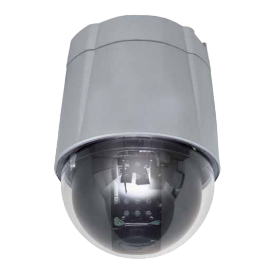
3.5-94.5 mm 27X motorized day/night dome colour camera
•
Cámara de cúpula en color motorizada día/noche 3,5-94,5 mm 27X
•
Câmara a cores cúpula motorizada diurna/nocturna 3,5-94,5 mm 27X
Kamera kolorowa ze sklepieniem, z napędem, dzień/noc 3,5–94,5 mm 27X
•
430 522
User manual
430 522
Advertisement
Table of Contents

Related Manuals for LEGRAND 430 522


Summary of Contents for LEGRAND 430 522
-
Page 1: User Manual
3.5-94.5 mm 27X motorized day/night dome colour camera • Cámara de cúpula en color motorizada día/noche 3,5-94,5 mm 27X • Câmara a cores cúpula motorizada diurna/nocturna 3,5-94,5 mm 27X Kamera kolorowa ze sklepieniem, z napędem, dzień/noc 3,5–94,5 mm 27X • 430 522 430 522 User manual... - Page 2 FEATURES • Powerful Zoom Camera & Setup Options 27x Optical Zoom, 12x Digital Zoom (324x Max. zoom magnification) High light compensation Privacy Mask Day & Night Focus Mode : Auto-Focus, Manual Focus, Semi-Auto Focus OSD Menu Image Sensor : ¼” Sony interline Transfer CCD •...
- Page 3 Before carrying out the installation, read the instructions and take account of the product’s specific mounting location. Do not open up, dismantle, alter or modify the device except where specifically required to do so by the instructions. All Legrand products must be opened and repaired exclusively by personnel trained and approved by Legrand.
-
Page 4: Package Component
PACKAGE COMPONENT • Product & Accessories • Optional... -
Page 5: Main Part Description
MAIN PART DESCRIPTION • Dome Cover Do not detach the protection vinyl from the dome cover before finishing all the installation process to protect the dome cover from scratches or dust. • Terminal Cover This is used to install the camera directly on the ceiling or attach to the other brackets such as in-ceiling, ceiling and wall mount. - Page 6 TERMINAL COVER DISASSEMBLY b Turn main body on its axis in a Remove the Lockup Screw as shown bellow CCW(Counter-clockwise) direction and separate it from Terminal Cover. TERMINAL COVER ASSEMBLY c Check if the summit of the Plate Spring d Check the 2 mold line for assembly is located at the arrow mark as shown in before starting assembly.
-
Page 7: Dip Switch Setup
DIP SWITCH SETUP • Before you install the camera, you should set the DIP switches to configure the camera ID, communication protocol. Do not use the ISP connector. (Authorized person only !) • Camera ID Setup & & & (& •... - Page 8 • Communication Protocol Setup • Select an appropriate Protocol with the DIP switch combination. Switch State Protocol (Pin 1) (Pin 2) (Pin 3) PELCO-D, 2400 bps PELCO-D, 9600 bps PELCO-P , 4800 bps PELCO-P , 9600 bps Otherwise Reserved • If you want to control using DVR or P/T controller, their protocol must be identical to camera. Otherwise, you can not control the camera.
- Page 9 • Terminal Resistor Setup • The terminal resistor is used if your system is one of following two cases. • Case 1: Control cable between camera and controller is relatively very long (1:1 connection) If communication cable is very long, the electrical signal will bound in the terminal point. This reflected signal cause distortion of original signal.
-
Page 10: Direct Installation On The Ceiling
DIRECT INSTALLATION ON THE CEILING a To pass cables to upside of ceiling, please, make b For cable connection, remove the pre-defined hole about 50~60mm hole on the ceiling panel. mark on the Rubber Gasket and locate the summit of the Plate Spring at the arrow mark as shown in the dotted circle. - Page 11 INSTALLATION USING REF . 391885 IN-CEILING MOUNT BRACKET a Cut the panel of ceiling as shown bellow. b Assemble Terminal Cover of camera to the In- Ceiling Mount Bracket as shown bellow. c Locate the summit of the plate spring at the arrow d Assemble main body to Terminal Cover and insert mark as shown in the dotted cir the assembly into ceiling tex.
- Page 12 INSTALLATION USING REF . 391883 CEILING MOUNT BRACKET a To pass cables to upside of ceiling, please make b Assemble Terminal Cover to Ceiling Mount Bracket about 50~60mm hole on the ceiling panel and with 3 screws. (Do not use Rubber Gasket !) attach the Ceiling mount bracket on it.
- Page 13 INSTALLATION USING REF . 391847 WALL MOUNT BRACKET a Install Wall Mount Bracket on wall. b Assemble Terminal Cover to Wall Mount Bracket with 3 screws. (Do not use Rubber Gasket !) Locate the summit of the Plate Spring at the arrow mark.
-
Page 14: Wiring And Cabling
WIRING AND CABLING &)!*+, &)!*", Terminal Cover • Port Connexion • Please, check the voltage and current capacity of rated power carefully. Rated power is indicated in the back of main unit. Rated Power Input Voltage Range Current Consumption DC 12V DC 11V ~ 15V 0,75 A •... - Page 15 • Alarm I/O Connection • Sensor Input Before connecting sensors, check driving voltage and output signal type of the sensor. Since output signal types of the sensors are divided into Open Collector and Voltage Output type in general, the cabling must be done properly after considering these typed.
-
Page 16: Check Points Before Operation
CHECK POINTS BEFORE OPERATION • Before turning on the system, check if the wire(s) and cable(s) are connected properly. • Check if the camera ID on the controller is properly selected. The camera ID must be identical to that of the target camera. -
Page 17: Specifications
SPECIFICATIONS • Appearance CAMERA PART Video Signal System 1/4'' Super HAD color CCD Max. Pixels 795(H)x96(V) 470K Effective Pixels 752(H)x582(V) 440K Horizontal Res. 550 TV Line(Color), 680 TV Line(B/W) S/N Ratio 50 dB (AGC Off) Zoom x27 Optical Zoom, x12 Digital Zoom Focal length f=3.5~94.5 mm (F1.6~2.9) Main Unit... - Page 18 DIMENSION • Main Body & Terminal cover • In-Ceiling Mount Bracket ref. 391885 • Ceiling Mount Bracket ref. 391883 • Wall Mount Bracket ref. 391847 Unit (mm)
Need help?
Do you have a question about the 430 522 and is the answer not in the manual?
Questions and answers