Table of Contents
Advertisement
Quick Links
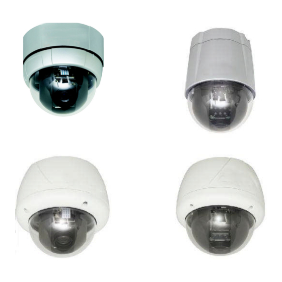
3.6-44.3mm 12X motorized day/night dome colour camera
4 305 21
3.5-94.5 mm 27X motorized day/night dome colour camera
4 305 22
3.6-44.3mm 12X weatherproof motorized day/night dome colour camera
4 305 23
3.5-94.5 mm 27X weatherproof motorized day/night dome colour camera
4 305 24
3.5-129.5 mm 37X weatherproof motorized day/night dome colour camera
4 305 25
USER MANUAL
4 305 21
4 305 23
4 305 22
4 305 24/25
Advertisement
Table of Contents

Subscribe to Our Youtube Channel
Related Manuals for LEGRAND 4 305 21


Summary of Contents for LEGRAND 4 305 21
-
Page 1: User Manual
3.6-44.3mm 12X motorized day/night dome colour camera 4 305 21 3.5-94.5 mm 27X motorized day/night dome colour camera 4 305 22 3.6-44.3mm 12X weatherproof motorized day/night dome colour camera 4 305 23 3.5-94.5 mm 27X weatherproof motorized day/night dome colour camera 4 305 24 3.5-129.5 mm 37X weatherproof motorized day/night dome colour camera... -
Page 2: Important Safety Guide
Important Safety Guide Read, heed and follow all the Instructions Read all the safety and operating instructions before using the product. Keep this manual Keep this manual for reference in future. Attachments / Accessories Use only the attachments or accessories specified by the manufacturer. Installation ... -
Page 3: Caution
CAUTION Operating Before using, make sure that the power supply and others are properly installed. While operating, if any abnormal condition or malfunction is observed, stop using the product immediately and then contact your local dealer. Handling Do not disassemble or tamper with the parts inside the product. -
Page 4: Table Of Contents
Installation with Ceiling Mount Bracket (4 305 23/4 305 24/4 305 25 Models)........ 25 Installation with Wall Mount Bracket (4 305 23/4 305 24/4 305 25 Models) ........26 Wiring and Cabling (4 305 21/4 305 23/4 305 24/4 305 25) ..............27 2.10 Operation...............................32... - Page 5 Camera Setup (Dome Camera Setup Menu)..................43 Motion Setup .............................. 47 Preset Setup ............................... 50 Swing Setup ............................... 53 Pattern Setup.............................. 54 Group Setup ............................... 55 4.10 System Initialization..........................58 4.11 Specifications ............................60 Dimension..............................65...
-
Page 6: Introduction
1 INTRODUCTION 1.1 MODEL CODE Ref. 4 305 21 4 305 22 4 305 23 4 305 24 4 305 25 Mini Mini plastic Aluminium Aluminium Mini Aluminium Aluminium with small Serie with with with fan/heater fan/heater fan/heater fan/heater Outdoor serie... - Page 7 4 305 22 : 4 alarm sensor inputs and 2 alarm output relays 4 305 21/4 305 23/4 305 24/4 305 25 : 3 alarm sensor inputs and 1 alarm sensor outputs Alarm sensor input is decoupled with photo-couplers to avoid external electric noise and shock perfectly.
- Page 8 Both of N.O.(Normal Open) sensors and N.C.(Normal Close) sensors can be used and the signal range of the sensor input is from DC 5.0V to 12.0V for various applications. The camera can be set to move to a Preset position or to run functions such as Pattern, Swing and Group when there are external sensor activations.
-
Page 9: Package Component
1.3 Package Component (4 305 21 Model) Product & Accessories Product & Accessories Main Body & Surface Mount Bracket Main Body & Surface Mount Bracket Default Accessories Accessories [Main Cable, Calblock, Screws : Tapping M4 [Main Cable, Calblock, Screws : Tapping M416, Tapping M425, Machine M36, Machine M3... - Page 10 (4 305 23/4 305 24/4 305 25 Models) s) Product & Accessories Default Accessories Default Accessories Main Body & Surface Mount Bracket Main Body & Surface Mount Bracket [Main Cable, Wrench] [Main Cable, Wrench] Wall Mount Bracket Wall Mount Bracket Accessories for The Models with Alarm In/Out Accessories for The Models with Alarm In/Out Function [I/O Cable]...
-
Page 11: Main Part Description
1.4 Main Part Description (4 305 21 Model) Surface Mount Bracket Mounting Screw Hole Main Connector Sensor I/P Port Dome Cover Assembly Stud Dome Cover Lock-up Screw DIP Switch Dome Cover Dome Cover Do not detach the protection vinyl from the dome cover before finishing all the installation process to protect the dome cover from scratches or dust. - Page 12 (4 305 22 Model) Dome Cover Do not detach protection vinyl from dome cover before finishing all installation Do not detach protection vinyl from dome cover before finishing all installation Do not detach protection vinyl from dome cover before finishing all installation process to protect dome cover from process to protect dome cover from scratches or dust es or dust...
- Page 13 Terminal Cover Disassembling ① ② Turn main body on its axis in Remove the Lockup Screw as shown bellow. CCW(Counter-clockwise) direction and separate it from Terminal Cover. Terminal Cover Assembling ① ② Check if the summit of the Plate Spring is Check the 2 mold line for assembly before located at the arrow mark as shown in the dotted starting assembly.
- Page 14 (4 305 23 Model) Mo u n t in g Scr ew Ho le Mo u n t in g Ho o k DIP Switch Main Co n n ect o r Sen s o r I/ O Po r t Do m e Co ver Main Body / Terminal Cover ...
-
Page 15: Installation
2 INSTALLATION 2.1 DIP Switch Setup (4 305 21/4 305 23/4 305 24/4 305 25 4 305 25 models) Before installing the camera, set up the DIP switch to configure the camera ID and the Before installing the camera, set up the DIP switch to configure the camera ID and the communication communication protocol. -
Page 16: Camera Id Setup
Camera ID Setup ID numbers of cameras are set up with binary numbers. See the ID numbers of cameras are set up with binary numbers. See the examples shown below. Binary Value Ex : ID=5 Ex : ID=10 The camera ID range is “1~255”. Camera ID must not be Camera ID must not be “0”! Factory default of Camera ID is 1. -
Page 17: Terminal Resistor Setup
Terminal resistor Setup Terminal resistor is used if your system is one of following two Terminal resistor is used if your system is one of following two cases. Case1: Control cable between camera and controller is relatively very long (1:1 connection) Case1: Control cable between camera and controller is relatively very long (1:1 connection) Case1: Control cable between camera and controller is relatively very long (1:1 connection) If communication cable is very long, the electrical signal will bound in the... - Page 18 Sensor Type Setup If you want to use Alarm Input, the types of sensor must be selected. The sensor types are Normal Open and Normal. Normal Open Output Voltage is high state when sensor is activated. Normal Close Output Voltage is high state when sensor is not activated.
-
Page 19: In-Ceiling Mount Installation (4 305 21 Model)
2.2 In-Ceiling Mount Installation (4 305 21 Model) ① ② Remove the ceiling tile from the ceiling and cut a Connect the wiring and cabling and attach the hole whose diameter is 110mm on the ceiling tile to pass camera to the ceiling tile. (Tapping M416). -
Page 20: Installation With Surface Mount Bracket (4 305 21 Model)
2.3 Installation with Surface Mount Bracket (4 305 21 Model) ① ② Remove the ceiling tile from the ceiling and Prepare the surface mount bracket. Pull the wires and cut a hole whose diameter is 30~40mm on the ceiling cables for the system as below. Attach the surface mount tile to pass the wires and cables through to the upside bracket to the mounting surface. -
Page 21: Direct Installation On The Ceiling (4 305 22 Model)
2.4 Direct Installation on the Ceiling ( Direct Installation on the Ceiling (4 305 22 model) ① ② To pass cables to upside of ceiling, please, To pass cables to upside of ceiling, please, For cable connection, remove the pre cable connection, remove the pre-defined hole mark on make about 50~60mm hole on the ceiling make about 50~60mm hole on the ceiling panel. -
Page 22: Installation Using In-Ceiling Mount Bracket (4 305 22 Model)
Installation using In-Ceiling Mount Bracket Ceiling Mount Bracket (4 305 22 model) ① ② Cut the panel of ceiling as shown bellow. Cut the panel of ceiling as shown bellow. Assemble Terminal Cover of camera to the Assemble Terminal Cover of camera to the In-Ceiling Mount Bracket as shown bellow. -
Page 23: Installation Using Ceiling Mount Bracket (4 305 22 Model)
2.6 Installation using Ceiling Mount Bracket (4 305 22 model) ① ② To pass cables to upside of ceiling, please Assemble Terminal Cover to Ceiling Mount make about 50~60mm hole on the ceiling panel and Bracket with 3 screws. (Do not use Rubber Gasket !) attach the Ceiling mount bracket on it. -
Page 24: Installation Using Wall Mount Bracket (4 305 22 Model)
2.7 Installation using Wall Mount Bracket (4 305 22 model) ① ② Install Wall Mount Bracket on wall. Assemble Terminal Cover to Wall Mount Bracket with 3 screws. (Do not use Rubber Gasket Locate the summit of the Plate Spring at the arrow mark. -
Page 25: Installation With Ceiling Mount Bracket (4 305 23/4 305 24/4 305 25 Models)
2.8 Installation with Ceiling Mount Bracket (4 305 23/4 305 24/4 305 25 Models) ① ② Remove the ceiling tile from the ceiling and cut a Pull the wire(s) and cable(s) for the system as hole whose diameter is 30~40mm on the ceiling tile to pass below. -
Page 26: Installation With Wall Mount Bracket (4 305 23/4 305 24/4 305 25 Models)
2.9 Installation with Wall Mount Bracket (4 305 23/4 305 24/4 305 25 Models) ① ② Make a hole whose diameter is 30~40mm on the Pull the wire(s) and cable(s) for the system as mounting surface to pass the wire(s) and cable(s) through below. -
Page 27: Wiring And Cabling (4 305 21/4 305 23/4 305 24/4 305 25)
2.10 Wiring and Cabling (4 305 21/4 305 23/4 305 24/4 305 25) POWER MAIN CABLE MONITOR RS-485 CONTROLLER / DVR I/O CABLE SENSOR I/O DOOR SENSOR SWITCH Port Description Main Cable Port Pin Number (RJ45) Connector / Wire Color... - Page 28 Carefully check the voltage and current capacity of the rated power. The rated power is indicated in the back of main unit. Model Input Voltage Range Current Consumption Current Consumption 4 305 21 0.8 A DC 11V ~ 15V 4 305 23/4 305 24/4 305 25 2.5 A ...
-
Page 29: Alarm Input
Video Use BNC coaxial cable only. Alarm Input Before connecting sensors, check driving voltages and output signal types of the sensors. Since output signal Before connecting sensors, check driving voltages and output signal types of the sensors. Since output signal Before connecting sensors, check driving voltages and output signal types of the sensors. -
Page 30: Power Connection
Wiring and Cabling (4 305 22 model) model) Power Connection Please, check the voltage and current capacity of rated power carefully. Rated power is indicated in the back of main unit. check the voltage and current capacity of rated power carefully. Rated power is indicated in the back of main unit. check the voltage and current capacity of rated power carefully. - Page 31 Alarm I/O Connection Sensor Input Before connecting sensors, check driving voltage and output signal type of the sensor. Since output signal types of Before connecting sensors, check driving voltage and output signal type of the sensor. Since output signal types of Before connecting sensors, check driving voltage and output signal type of the sensor.
-
Page 32: Operation
3 Operation 3.1 Check Points before Operation Before turning on the system, check if the wire(s) and cable(s) are connected properly. Check if the camera ID on the controller is properly selected. The camera ID must be identical to that of the target camera. -
Page 33: Osd Menu
3.3 OSD Menu Function With OSD menu, the system can be properly configured for each application. Entering into OSD Go Preset [95] 3.4 Reserved Presets (Hot Keys) Description Some Preset numbers are reserved to change some parameters without entering into OSD menu. ... -
Page 34: Preset
3.5 Preset Function MAX. 127 positions positions are programmable. The Preset number can be The Preset number can be assigned from 1 to 128 except 95. Preset 95 is reserved for entering into OSD menu. Camera parameters such as except 95. -
Page 35: Pattern
3.7 Pattern Function This function is that the camera memorizes the path (mostly is that the camera memorizes the path (mostly curve path) by the joystick of the curve path) by the joystick of the controller and revives the trajectory operated by joystick as closely as possible. controller and revives the trajectory operated by joystick as closely as possible. -
Page 36: Group
3.8 Group Function This function is that the camera memorizes the combination of is that the camera memorizes the combination of Presets, Pattern and/or Swings s, Pattern and/or Swings sequently and runs Preset Presets, Pattern and/or Swings repetitively. MAX. 8 sets of Group are MAX. -
Page 37: Other Functions
3.9 Other Functions Power Up This setting defines a specific activity (Preset, Pattern, Swing and Group) to be performed in the Action event that the power to the camera is cycled. This function enables the user to resume, after turning on power, the last action being executed before turning off the power. -
Page 38: Osd Display
3.10 OSD Display P/T/Z Information Displays the amount of pan from zero degree Displays the amount of pan from zero degree vertical, the amount of tilt from zero degree vertical, the amount of tilt from zero degree horizontal and c horizontal and current compass direction. -
Page 39: Osd Menu
4 OSD MENU 4.1 Quick Programming Guide The menu items with < > always have ve sub-menus. To go to submenus or make the cursor move to the right s or make the cursor move to the right, press NEAR key. ... -
Page 40: Display Setup
4.3 Display setup Display setup allows you to program how labels are Display setup allows you to program how labels are displayed on the monitor. In case of AUTO, the labels are displayed on displayed on the monitor. In case of AUTO, the labels are displayed on the monitor when there are any changes in parameters. -
Page 41: Privacy Zone Mask Setup
Compass Direction setup Move the camera to a target position and press Move the camera to a target position and press NEAR button to save the direction as North. The direction is the reference button to save the direction as North. The direction is the reference direction to assign other compass directions 4.4 Privacy Zone Mask Setup Privacy Zone Mask allows the user to program 4 rectangulars... - Page 42 Privacy Zone Mask Area Setup Move your camera to an area to mask. Then a mask and the menu to adjust the mask size will be displayed. Move your camera to an area to mask. Then a mask and the menu to adjust the mask size will be displayed. Move your camera to an area to mask.
-
Page 43: Camera Setup (Dome Camera Setup Menu)
4.5 Camera Setup (Dome Camera Setup Menu) (Dome Camera Setup Menu) Sets the general functions of zoom camera module. Sets the general functions of zoom camera module. Focus Mode [AUTO/MANUAL/SEMIAUTO] [AUTO/MANUAL/SEMIAUTO] Sets camera Focus mode. mode. SEMIAUTO Mode This mode automatically exchanges focus modes between Manual Focus mode and Auto Focus This mode automatically exchanges focus modes between Manual Focus mode and Auto Focus This mode automatically exchanges focus modes between Manual Focus mode and Auto Focus... - Page 44 White Balance Setup WB Mode [AUTO/MANUAL] Retains color balance over a color temperature range. In auto mode, this feature automatically Retains color balance over a color temperature range. In auto mode, this feature automatically Retains color balance over a color temperature range. In auto mode, this feature automatically processes the viewed image.
- Page 45 Brightness [0~64] Adjusts the brightness of the images. Iris, The Shutter Speed and Gain are adjusted automatically in correspondence with each numeric value. IRIS [AUTO/MANUAL(0~64)] Sets Iris to operate automatically or at a user-defined level. If Iris is set to Auto, Iris has higher priority in adjusting AE and Shutter Speed is fixed.
- Page 46 HLC (High Light Compensation) Setup Limit [AUTO/MANUAL] When there are too bright lights, this function blocks light sources on the images to have better images. For example, when there is a car coming to a camera at night, this function bocks car headlights to recognize its number plate.
-
Page 47: Motion Setup
4.6 Motion Setup Sets the general functions of Pan/Tilt motions. Sets the general functions of Pan/Tilt motions. Motion Lock [ON/OFF] If Motion Lock is set to ON, it is impossible to set up and delete Preset, Swing, Pattern and Group. It is If Motion Lock is set to ON, it is impossible to set up and delete Preset, Swing, Pattern and Group. -
Page 48: Parking Action Setup
Parking Action Setup This feature allows the camera to begin a specified action after a This feature allows the camera to begin a specified action after a programmed time of inactivity. time of inactivity. Park Enable [ON/OFF] If Park Enable is set to ON, the camera runs an If Park Enable is set to ON, the camera runs an assigned function automatically if there is no PTZ assigned function automatically if there is no PTZ command during the programmed "Wait Time". - Page 49 Hold Time [ENDLESS / 1~59 SEC. / 1~180 MIN.] Sets the time period for the action which is run by external sensor activation. After the time period passes, the action pre-defined in “Post Action” runs sequentially in succession to the action by external sensor activation.
-
Page 50: Preset Setup
4.7 Preset Setup Preset Number [1~128] Selects a preset number to set up. If a selected preset is already defined, the camera moves to the Selects a preset number to set up. If a selected preset is already defined, the camera moves to the Selects a preset number to set up. - Page 51 ○, 1 Use the Joystick to move the camera to a desired position. Use the Joystick to move the camera to a desired position. ○, 2 Save the preset position by pressing NEAR NEAR key. ○, 3 Press FAR key to cancel targeting the preset position. key to cancel targeting the preset position.
- Page 52 Relay Out Setup (4 305 22) Relay Out [ON/OFF] Sets Relay Outputs for assigned preset. Sets Relay Outputs for assigned preset.
-
Page 53: Swing Setup
4.8 Swing Setup Swing Number [1~8] Selects a Swing number to edit. If the selected Swing is not defined, "NOT USED" is Selects a Swing number to edit. If the selected Swing is not defined, "NOT USED" is Selects a Swing number to edit. If the selected Swing is not defined, "NOT USED" is displayed in the 1st Position and the 2nd Position. -
Page 54: Pattern Setup
4.9 Pattern Setup Pattern Number [1~4 ] Selects a Pattern number to edit. If the selected pattern number is not defined, "UNDEFINED" will Selects a Pattern number to edit. If the selected pattern number is not defined, "UNDEFINED" will Selects a Pattern number to edit. -
Page 55: Group Setup
4.10 Group Setup Group Number [1~8] Selects a Group number to edit. Group number to edit. If the selected Group number is not defined, "UNDEFINED" will be displayed under selected Group number is not defined, "UNDEFINED" will be displayed under selected Group number is not defined, "UNDEFINED"... - Page 56 3) Define Action, Dwell time and Option. Define Action, Dwell time and Option. Note that the dark rectangular is the cursor. Move the cursor Note that the dark rectangular is the cursor. Move the cursor Left/Right to select an item and move cursor Up/Down to change each parameter. to change each parameter.
- Page 57 Step ②). Move the cursor 5) After finishing editing a Action, press Near key to go to a Action, press Near key to go to the previous-upper level menu (Step Action number and repeat Step ② ~ Step ④ to keep editing the selected Up/Down to select an Action number and repeat Step the selected Group.
-
Page 58: System Initialization
4.11 System Initialization Clear All Data Deletes all configuration data and the system is set to the factory default. Deletes all configuration data and the system is set to the factory default. Deletes all configuration data and the system is set to the factory default. ... -
Page 59: Factory Default
Factory Default Display Parameters Camera Parameters Camera ID Focus Mode SemiAuto PTZ Information AUTO Digital Zoom Action Title AUTO Image Flip Preset Label AUTO Sharpness Stabilization Alarm I/O AUTO White Balance AUTO North Direction Backlight Pan 0 Privacy Zone Undefined Day&Night AUTO... -
Page 60: Specifications
5 Specifications CAMERA PART (4 305 21/4 305 23) Video Signal Format Image Sensor Sony 1/4'' Super HAD CCD Total Pixels 795(H)596(V) 470K Effective Pixels 752(H)582(V) 440K Horizontal Resolution 560 TV Lines(Color), 600 TV Lines(B/W) Video Signal-to-Noise 52 dB (AGC Off) - Page 61 Specifications (4 305 22) Model 4 305 22 Video Signal System 1/4'' Super HAD color CCD Max. Pixels 795(H)596(V) 470K Effective Pixels 752(H)582(V) 440K Horizontal Res. 550 TV Line(Color), 680 TV Line(B/W) S/N Ratio 50 dB (AGC Off) Zoom 27x Optical Zoom, 12x Digital Zoom Focal length f=3.5~94.5mm (F1.6~2.9) Min.
- Page 62 Specifications (4 305 24 – 4 305 25 CAMERA PART 4 305 24 4 305 25 Video Signal Format Image Sensor 1/4'' Interline Transfer CCD Total Pixels 795(H)596(V) 470 K Effective Pixels 752(H)582(V) 440 K Horizontal Resolution 550 TV Lines(Color), 680 TV Lines(B/W) Video Signal-to-Noise 50 dB (AGC Off) Optical Zoom...
- Page 63 1 Output, Relay Output, MAX. Load DC24V 1A / AC125V 0.5A Always ON Heater Operation Start from Internal Temperature 10C 0C ~ 40C (4 305 21/4 305 22 Models) Operation Temperature -30C ~ 50C (4 305 23/4 305 24/4 305 25 Models) RATED POWER 4 305 21 DC 12V / 0.8 A...
- Page 64 MECHANICAL 4 305 21 Model Surface Mount Ceiling Mount Wall Mount Dome Polycarbonate Material Internal Polycarbonate, ABS External Polycarbonate Dome Size 107.5 mm / 4.2” Dimension 132.4129.5 mm 132.4187.5 mm 213.2207.5 mm Weight (kg) Approx 0.7 Approx 0.8 Approx 0.85 kg...
-
Page 65: Dimension
5.1 Dimension (4 305 21 Model) Main Body Surface Mount Type [Unit : mm]... - Page 66 (4 305 22 Model) Main Body & Terminal Cover In-Ceiling Mount Bracket Ceiling Mount Bracket Wall Mount Bracket Unit (mm)
- Page 67 (4 305 23 Model) Main Body Ceiling Mount Type Wall Mount Type [Unit : mm]...
- Page 68 (4 305 24/4 305 25 Model) Main Body Ceiling Mount Type Wall Mount Type [Unit : mm]...
Need help?
Do you have a question about the 4 305 21 and is the answer not in the manual?
Questions and answers