Table of Contents
Advertisement
Quick Links
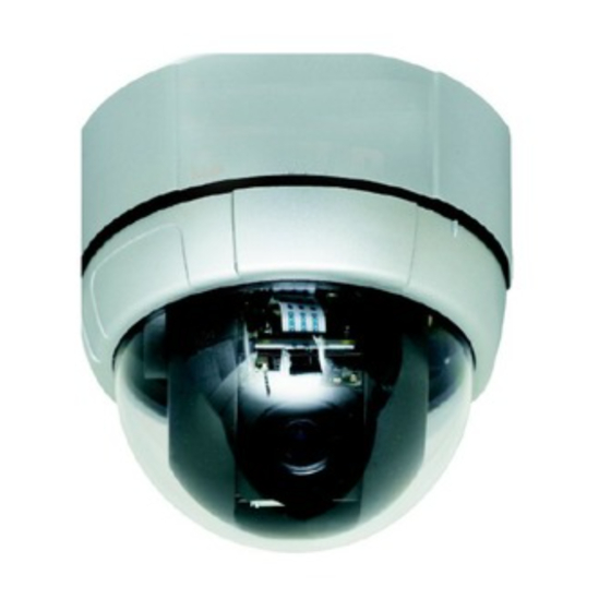
Caméra couleur dôme motorisée jour/nuit 3,8-38 mm 10X
3.8-38 mm 10X motorized day/night dome colour camera
Cámara de cúpula en color motorizada día/noche 3,8-38 mm 10X
Câmara a cores cúpula motorizada diurna/nocturna 3,8-38 mm 10X
kamera kolorowa ze sklepieniem, z napędem, dzień/noc 3,8–38 mm 10X
430 521
430 521
User manual
Advertisement
Table of Contents

Related Manuals for LEGRAND 430 521


Summary of Contents for LEGRAND 430 521
-
Page 1: User Manual
3.8-38 mm 10X motorized day/night dome colour camera Cámara de cúpula en color motorizada día/noche 3,8-38 mm 10X Câmara a cores cúpula motorizada diurna/nocturna 3,8-38 mm 10X kamera kolorowa ze sklepieniem, z napędem, dzień/noc 3,8–38 mm 10X 430 521 430 521 User manual... - Page 2 FEATURES Powerful Zoom Camera & Setup Options 10x Optical Zoom, 10x Digital Zoom (100x Max. zoom magnification) High light compensation Privacy Mask Day & Night Focus Mode : Auto-Focus, Manual Focus, Semi-Auto Focus OSD Menu Image Sensor : ¼” Sony interline Transfer CCD Powerful Pan/Tilt Functions MAX.
- Page 3 Before carrying out the installation, read the instructions and take account of the product’s specific mounting location. Do not open up, dismantle, alter or modify the device except where specifically required to do so by the instructions. All Legrand products must be opened and repaired exclusively by personnel trained and approved by Legrand.
-
Page 4: Package Component
PACKAGE COMPONENT Product & Accessories... -
Page 5: Main Part Description
MAIN PART DESCRIPTION Product & Accessories Surface Mount B racket Mounting Screw Hole Main Connector Sensor I/O Port Dome Cover A ssembly Stud Dome Cover L ock-up Screw DIP Switch Dome Cover Dome Cover Do not detach the protection vinyl from the dome cover before finishing all the installation process to protect the dome cover from scratches or dust. -
Page 6: Dip Switch Setup
DIP SWITCH SETUP Before installing the camera, set up the DIP switch to configure the camera ID and the communication protocol. Product & Accessories Camera ID Setup DID numbers of cameras are set up with binary numbers. See the examples shown below. Binary Value ex: ID = 5 ex: ID = 10... - Page 7 Communication Protocol Setup Select an appropriate Protocol with the DIP switch combination. Switch Mode Protocol (Pin 1) (Pin 2) (Pin 3) PELCO-D, 2400 bps PELCO-D, 9600 bps PELCO-P , 4800 bps PELCO-P , 9600 bps Others Reserved Match the camera protocol with the camera protocol in the setting of your DVR or controller to control the camera.
-
Page 8: In-Ceiling Mount Installation
IN-CEILING MOUNT INSTALLATION Remove the ceiling tile from the ceiling and cut Connect the wiring and cabling and attach the a hole whose diameter is 110mm on the ceiling camera to the ceiling tile. (Tapping M4x16) tile to pass the wires and cables through to the upside of ceiling. -
Page 9: Installation With Surface Mount Bracket
INSTALLATION WITH SURFACE MOUNT BRACKET Remove the ceiling tile from the ceiling and cut a Prepare the surface mount bracket. hole whose diameter is 30~40mm on the ceiling Pull the wires and cables for the system as tile to pass the wires and cables through to the below. - Page 10 WIRING AND CABLING POWE R B NC MA I N C A B L E MONITOR A UDI O SPE A K E R C AB L E R S-485 C ONT R OL L E R / DV R I /O CA B L E SE NSOR I/O DOOR...
- Page 11 Power Description Carefully check the voltage and current capacity of the rated power. The rated power is indicated in the back of main unit. Input Voltage Range Current Consumption DC 11V ~ 15V 0,8 A For the DC input models, be careful with the polarity of DC power. The system should be permanentally damaged by wrong DC input.
- Page 12 Alarm Input Before connecting sensors, check driving voltages and output signal types of the sensors. Since output signal types of the sensors are divided into Open Collector type and Voltage Output type in general, the wiring must be done properly after considering those types. Signal Description IN COM+...
-
Page 13: Check Points Before Operation
CHECK POINTS BEFORE OPERATION Before turning on the system, check if the wire(s) and cable(s) are connected properly. Check if the camera ID on the controller is properly selected. The camera ID must be identical to that of the target camera. The camera ID can be checked by reading the DIP switch of the camera or on OSD. If your controller supports multi-protocols, the protocol must be changed to match to that of the camera. -
Page 14: Specifications
SPECIFICATIONS CAMERA PART Video Signal Format Image Sensor 1/4'' Interline Transfer CCD Total Pixels 795(H)x596(V) 470K Effective Pixels 752(H)x582(V) 440K Horizontal Resolution 500 TV Lines(Color), 570 TV Lines(B/W) Video Signal-to-Noise 50 dB (AGC Off) Zoom x10 Optical Zoom, x10 Digital Zoom Forcal Length F1.8, f=3.8~38mm Angle of View... - Page 15 MECHANICAL Surface Mount Ceiling Mount Dome Polycarbonate Material Internal Polycarbonate, ABS External Polycarbonate Dome Size Ø 107,5 mm/ Ø 4,2” Dimension 132,4x129,5 mm 132,4 x 187,5 mm Weight (kg) Approx 0,7 Approx 0,8 [Note] Check the voltage and current capacity of rated power carefully.
- Page 16 DIMENSION Main Body Surface Mount Type...
Need help?
Do you have a question about the 430 521 and is the answer not in the manual?
Questions and answers