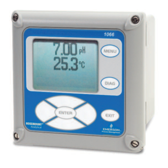
Emerson Rosemount 1066 Instruction Manual
Smart-enabled, 2-wire transmitter
Hide thumbs
Also See for Rosemount 1066:
- Instruction manual (80 pages) ,
- Quick start manual (44 pages) ,
- Instruction manual (28 pages)

Related Manuals for Emerson Rosemount 1066


Summary of Contents for Emerson Rosemount 1066
- Page 1 Instruction Manual LIQ-MAN-1066 Rev. J April 2017 Rosemount 1066 ™ Smart-Enabled, 2-Wire Transmitter...
- Page 3 Manual is not the correct manual, telephone 1-800-854-8257 and the requested manual will be provided. Save this Instruction Manual for future reference. • If you do not understand any of the instructions, contact your Emerson representative for clarification. • Follow all warnings, cautions, and instructions marked on and supplied with the product.
-
Page 4: About This Document
Non-Incendive Hazardous Location Approval. 9/2013 Added Section 10: HART Communications ® 11/2014 Changed agency water exposure testing description to “Type”. 05/2015 FM approvals updated. 04/2017 Updated the Address and Emerson logo. Also, updated the FM, CSA installation drawings and CE Declarations. -
Page 5: Table Of Contents
Instruction Manual Table of Contents LIQ-MAN-1066 April 2017 Contents Section 1: Quick Start Guide Quick start guide......................1 Section 2: Description and Specifications Features and Applications...................3 Specifications - General ....................4 pH/ORP ........................4 2.3.1 Performance Specifications - Transmitter (pH input) ........6 2.2.2 Performance Specifications - Transmitter (ORP input) ........6 Contacting Conductivity (Codes - C) ................7 2.4.1... - Page 6 Table of Contents Instruction Manual April 2017 LIQ-MAN-1066 4.2.1 Power Supply and Load Requirements ............17 4.2.2 Power Supply-Current Loop Wiring...............18 4.2.3 Current Output Wiring ..................19 Power Supply Wiring For 1066 FF ................20 4.3.1 Power Supply Wiring ..................20 Sensor Wiring to Main Board ..................21 Section 5: Intrinsically Safe Installation All Intrin sically Safe Installations ................27 Section 6: Display and operation...
- Page 7 Instruction Manual Table of Contents LIQ-MAN-1066 April 2017 pH Measurement Programming ................44 8.2.1 Description....................44 8.2.2 Measurement....................44 8.2.3 Preamp......................44 8.2.4 Solution Temperature Correction ..............45 8.2.5 Temperature Coefficient ................45 8.2.6 Resolution .....................45 8.2.7 Filter ......................45 8.2.8 Reference Impedance..................45 ORP Measurement Programming ................45 8.3.1 Measurement....................46 8.3.2...
- Page 8 Table of Contents Instruction Manual April 2017 LIQ-MAN-1066 8.6.1.3 Filter....................54 8.6.1.4 Free Chlorine pH Correction ............54 8.6.1.5 Manual pH Correction ..............54 8.6.1.6 Resolution..................54 8.6.2 Total Chlorine Measurement Programming..........55 8.6.2.1 Description ..................55 8.6.2.2 Measure..................55 8.6.2.3 Units ....................55 8.6.2.4 Filter....................55 8.6.2.5 Resolution..................55 8.6.3 Monochloramine Measurement Programming ..........56 8.6.3.1...
- Page 9 Instruction Manual Table of Contents LIQ-MAN-1066 April 2017 Toroidal Conductivity Calibration................74 9.5.1 Entering the Cell Constant................74 9.5.2 Zeroing the Instrument .................75 9.5.3 Calibrating the Sensor in a Conductivity Standard (in process cal) ....75 Calibration – Chlorine....................76 9.6.1 Calibration – Free Chlorine ................76 9.6.1.1 Zeroing the Sensor................77 9.6.1.2...
- Page 10 Table of Contents Instruction Manual April 2017 LIQ-MAN-1066 VIII...
-
Page 11: Section 1: Quick Start Guide
Instruction Manual Section 1: Quick Start Guide LIQ-MAN-1066 April 2017 Section 1: Quick Start Guide 1. For mechanical installation instructions, see page 14 for panel mounting and page 15 for pipe or wall mounting. 2. Wire the sensor to the main circuit board. See pages 21-23 for wiring instructions. - Page 12 Section 2: Description and Specifications Instruction Manual April 2017 LIQ-MAN-1066 Description and Specifications...
-
Page 13: Section 2: Description And Specifications
Diagnostics: The transmitter continuously monitors itself and the sensor for problems. A display banner on the screen alerts Technicians to Fault and/or Warning conditions. languages: Emerson extends its worldwide reach by offering eight languages – English, French, German, Italian, Spanish, Portuguese, Chinese and Russian. -
Page 14: Specifications - General
Section 2: Description and Specifications Instruction Manual April 2017 LIQ-MAN-1066 Specifications - General Case: Polycarbonate. IP66 (CSA, FM), Type 4X (CSA) Dimensions: Overall 155 x 155 x 131mm (6.10 x 6.10 x 5.15 in.). Cutout: 1/2 DIN 139mm x 139mm (5.45 x 5.45 in.) Conduit openings: Six. - Page 15 Instruction Manual Section 2: Description and Specifications LIQ-MAN-1066 April 2017 Input: One isolated sensor input. Measurement choices of pH/ORP, resistivity/conductivity/TDS, % concentration, total and free chlorine, monochloramine, dissolved oxygen, dissolved ozone, and temperature. For contacting conductivity measurements, temperature element can be a PT1000 RTD or a PT100 RTD.
-
Page 16: Ph/Orp
Section 2: Description and Specifications Instruction Manual April 2017 LIQ-MAN-1066 ph/ORp (Codes – p) For use with any standard pH or ORP sensor. SMART pH sensor with SMART pre-amplifiers from Rosemount. Measurement choices are pH, ORP, or Redox. The automatic buffer recognition fea- ture uses stored buffer values and their temperature curves for the most common buffer standards available worldwide. -
Page 17: Contacting Conductivity (Codes - C)
Instruction Manual Section 2: Description and Specifications LIQ-MAN-1066 April 2017 Contacting Conductivity (Codes – Measures conductivity in the range 0 to 600,000 S/cm (600mS/cm). Measurement choices are conductivity, resistivity, total dissolved solids, salinity, and % concentration. In addition, the “Custom Curve” feature allows users to define a three to five point curve to measure ppm, %, or a no unit variable. -
Page 18: Recommended Sensors For Conductivity
Section 2: Description and Specifications Instruction Manual April 2017 LIQ-MAN-1066 Recommended Sensors for Conductivity 2.4.2 All Rosemount 400 series conductivity sensors (Pt 1000 RTD) and 410VP 4-electrode sensor. Toroidal Conductivity (Codes – Measures conductivity in the range of 1 µS/cm to 2,000,000 µS/cm (2 S/cm). Measurement choices are conductivity, resistivity, total dissolved solids, salinity, and % concentration. -
Page 19: Recommended Sensors For Conductivity
Instruction Manual Section 2: Description and Specifications LIQ-MAN-1066 April 2017 zero cal Input filter: time constant 1 - 999 sec, default 2 sec. Response time: 3 seconds to 95% of final reading Salinity: Uses Practical Salinity Scale Total Dissolved Solids: Calculated by multiplying conductivity at 25 °C by 0.65 2.5.2 Recommended Sensors for Conductivity All Rosemount submersion/immersion and flow-through toroidal sensors. -
Page 20: Performance Specifications
Section 2: Description and Specifications Instruction Manual April 2017 LIQ-MAN-1066 2.6.5 Performance Specifications Resolution: 0.001 ppm or 0.01 ppm – selectable Input Range: 0nA – 100µA Temperature compensation: Automatic (via RTD) or manual (0-50 °C). Input filter: Time constant 1 - 999 sec, default 5 sec. Response time: 6 seconds to 95% of final reading 2.6.6 Recommended Sensors... -
Page 21: Ordering Information
Instruction Manual Section 2: Description and Specifications LIQ-MAN-1066 April 2017 Ordering Information The 1066 2-Wire Transmitter is intended for the continuous determination of pH, ORP (Redox), conductivity, (both contacting and toroidal), and for measurements using membrane-covered amperometric sensors (oxygen, ozone, free and total chlorine, and monochloramine). For free chlorine measurements, which often require continuous pH correction a second input for a pH sensor is available. - Page 22 Section 2: Description and Specifications Instruction Manual April 2017 LIQ-MAN-1066 Specifications...
-
Page 23: Section 3: Installation
Instruction Manual Section 3: Installation LIQ-MAN-1066 April 2017 Section 3: Installation unpacking and inspection Inspect the shipping container. If it is damaged, contact the shipper immediately for instructions. Save the box. If there is no apparent damage, unpack the container. Be sure all items shown on the packing list are present. - Page 24 Section 3: Installation Instruction Manual April 2017 LIQ-MAN-1066 FIGuRE 3-1. panel Mounting Dimensions Installation...
- Page 25 Instruction Manual Section 3: Installation LIQ-MAN-1066 April 2017 FIGuRE 3-2. pipe and wall mounting dimensions (Mounting bracket pN: 23820-00) Installation...
- Page 26 Section 3: Installation Instruction Manual April 2017 LIQ-MAN-1066 Installation...
-
Page 27: Section 4: Wiring
Instruction Manual Section 4: Wiring LIQ-MAN-1066 April 2017 Section 4: Wiring General 4.1.1 General Information The 1066 is easy to wire. All wiring connections are located on the main circuit board. The front panel is hinged at the bottom. The panel swings down for easy access to the wiring locations. 4.1.2 Digital Communication HART and F... -
Page 28: Power Supply-Current Loop Wiring
Section 4: Wiring Instruction Manual April 2017 LIQ-MAN-1066 4.2.2 Power Supply-Current Loop Wiring Refer to Figure 4-2. Run the power/signal wiring through the opening nearest TB-2. For optimum EMI/RFI protection: 1. Use shielded power/signal cable and ground the shield at the power supply. 2. -
Page 29: Current Output Wiring
Instruction Manual Section 4: Wiring LIQ-MAN-1066 April 2017 4.2.3 Current Output wiring The 1066 HART units are shipped with two 4-20mA current outputs. Current Output 1 is loop power; it is the HART communications channel. Current output 2 is available to report process temperature measured by the temperature sensing element or RTD within the sensor. -
Page 30: Power Supply Wiring For 1066 Ff
Section 4: Wiring Instruction Manual April 2017 LIQ-MAN-1066 power Supply Wiring For 1066-FF Power Supply Wiring 4.3.1 Run the power/signal wiring through the opening nearest TB2. Use shielded cable and ground the shield at the power supply. To ground the transmitter, attach the shield to TB2-3. Note: For optimum EMI/RFI immunity, the power supply/output cable should be shielded and enclosed in an earth-grounded metal conduit. -
Page 31: Sensor Wiring To Main Board
Instruction Manual Section 4: Wiring LIQ-MAN-1066 April 2017 Sensor Wiring to Main Board Wire the correct sensor leads to the main board using the lead locations marked directly on the board. Rosemount SMART pH sensors can be wired to the 1066 using integral cable SMART sensors or compatible VP8 pH cables. - Page 32 Section 4: Wiring Instruction Manual April 2017 LIQ-MAN-1066 FIGuRE 4-7. Contacting and Toroidal Conductivity sensor wiring to the 1066 circuit board DWG NO. 40106615 Wiring...
- Page 33 Instruction Manual Section 4: Wiring LIQ-MAN-1066 April 2017 FIGuRE 4-8. Chlorine, oxygen, ozone sensor wiring to 1066 printed circuit board (1066-Cl, 1066-DO, 1066-Oz) HINGE SIDE OF FRONT PANEL SENSOR WIRING (OUTPUT1) OUTPUT 2 LOOP PWR +24V ANODE +24V CATHODE SHLD RTD IN SHLD 1066 CIRCUIT BOARD...
- Page 34 Section 4: Wiring Instruction Manual April 2017 LIQ-MAN-1066 FIGuRE 4-9. power/Current loop wiring with wireless ThuM adaptor INSTALL PLUGS IN ALL OTHER OPENINGS AS NEEDED INNER ENCLOSURE LOOP POWER/THUM HINGE SIDE OF FRONT PANEL SENSOR WIRING (OUTPUT1) OUTPUT 2 LOOP PWR ANODE +24V +24V...
- Page 35 Instruction Manual Section 4: Wiring LIQ-MAN-1066 April 2017 FIGuRE 4-10. haRT loop power Wiring INSTALL PLUGS IN ALL OTHER OPENINGS AS NEEDED INNER ENCLOSURE HINGE SIDE OF FRONT PANEL SENSOR WIRING (OUTPUT1) OUTPUT 2 LOOP PWR ANODE +24V +24V CATHODE SHLD RTD IN HINGED PANEL...
- Page 36 Section 4: Wiring Instruction Manual April 2017 LIQ-MAN-1066 Wiring...
-
Page 37: Section 5: Intrinsically Safe Installation
Instruction Manual Section 4: Wiring LIQ-MAN-1066 April 2017 Section 5: Intrinsically Safe Installation all Intrin sically Safe Installations FIGuRE 5-1. CSa Installation Intrinsically Safe Installation... - Page 38 Section 4: Wiring Instruction Manual February 2017 LIQ-MAN-1066 FIGuRE 5-2. CSa Installation Intrinsically Safe Installation...
- Page 39 Instruction Manual Section 5: Intrinsically Safe Installation LIQ-MAN-1066 April 2017 FIGuRE 5-3. CSa Installation Intrinsically Safe Installation...
- Page 40 Section 5: Intrinsically Safe Installation Instruction Manual April 2017 LIQ-MAN-1066 FIGuRE 5-6. FM installation Intrinsically Safe Installation...
- Page 41 Instruction Manual Section 5: Intrinsically Safe Installation LIQ-MAN-1066 April 2017 FIGuRE 5-7. FM installation Intrinsically Safe Installation...
- Page 42 Section 5: Intrinsically Safe Installation Instruction Manual April 2017 LIQ-MAN-1066 FIGuRE 5-8. FM installation Intrinsically Safe Installation...
-
Page 43: Section 6: Display And Operation
Instruction Manual Section 6: Display and Operation LIQ-MAN-1066 April 2017 Section 6: Display and Operation user Interface The 1066 has a large display which shows the measurement readout and temperature in large digits and up to four additional process variables or diagnostic parameters concurrently. -
Page 44: Main Display
Section 6: Display and Operation Instruction Manual April 2017 LIQ-MAN-1066 Selection Keys: Surrounding the ENTER key, four Selection keys – up, down, right and left, move the cursor to all areas of the screen while using the menus. Selection keys are used to: 1. -
Page 45: Menu System
Instruction Manual Section 6: Display and Operation LIQ-MAN-1066 April 2017 The default display shows the live process measurement in the upper display area and temperature in the center display area. The user can elect to disable the display of temperature in the center dis- play area using the Main Format function. - Page 46 Section 6: Display and Operation Instruction Manual April 2017 LIQ-MAN-1066 Display and Operation...
-
Page 47: General
Instruction Manual Section 7: Transmitter programming LIQ-MAN-1066 April 2017 Section 7: Programming the Transmitter – Basics General Typical programming steps include the following listed procedures. Each of these programming functions are easily and quickly accomplished using the intuitive menu system. •... -
Page 48: Procedure
Section 7: Transmitter programming Instruction Manual April 2017 LIQ-MAN-1066 7.2.2 Procedure Follow the Reset Analyzer procedure (Section 7.8) to reconfigure the transmitter to display new measurements or measurement units. To change the specific measurement or measurement units for each measurement type, refer to the Program menu for the appropriate measurement (Section 6.0). -
Page 49: Setting A Security Code
Instruction Manual Section 7: Transmitter programming LIQ-MAN-1066 April 2017 FIGuRE 7-1. Configuring and Ranging the Current Outputs 1.234µS/cm 25.0ºC 1.234µS/cm 25.0ºC Output Range Output Range O1 SN 4mA: 0.000 OM 4mA: 1.000 O1 SN 20mA: 20.00 OM 20mA: 1.000% O2 SN 4mA: 0ºC OM 4mA: 1.000%... -
Page 50: Security Access
Section 7: Transmitter programming Instruction Manual April 2017 LIQ-MAN-1066 FIGuRE 7-2. Setting a Security Code 1.234 µS/cm 25.0 ºC Program Outputs Measurement Temperature 1.234 µS/cm 25.0 ºC Security Calibration/Hold: 000 All: 000 Security Diagnostic Setup Reset Analyzer Security access 7.6.1 How the Security Code Works When entering the correct access code for the Calibration/Hold security level, the Calibration and Hold menus are accessible. -
Page 51: Resetting Factory Default Settings
Instruction Manual Section 7: Transmitter programming LIQ-MAN-1066 April 2017 FIGuRE 7-3. using hold 1.234 µS/cm 25.0 ºC 1.234 µS/cm 25.0 ºC Hold outputs? Hold Hold: 7.7.2 Using the Hold Function To hold the outputs, 1. Press MENU. The main menu screen appears. Choose hold. 2. -
Page 52: Liq-Man
Section 7: Transmitter programming Instruction Manual April 2017 LIQ-MAN-1066 FIGuRE 7-4. Resetting Factory Default Settings Transmitter Programming... -
Page 53: Section 8: Programming Measurements
Instruction Manual Section 8: programming Measurements LIQ-MAN-1066 April 2017 Section 8: Programming Measurements Introduction The 1066 automatically recognizes the measurement input upon first power-up and each time the transmitter is powered. Completion of Quick Start screens upon first power up enable measurements, but additional steps may be required to program the transmitter for the desired measurement application. -
Page 54: Ph Measurement Programming
Section 8: programming Measurements Instruction Manual April 2017 LIQ-MAN-1066 ph Measurement programming 8.2.1 Description The section describes how to configure the 1066 transmitter for pH measurements. The follow- ing programming and configuration functions are covered. 1. Measurement type: pH Select pH, ORP, Redox. 2. -
Page 55: Solution Temperature Correction
Instruction Manual Section 8: programming Measurements LIQ-MAN-1066 April 2017 Solution Temperature Correction 8.2.4 1.234 µS/cm 25.0 ºC SN Sol’n Temp Corr. The display screen for selecting the Solution temperature correction Ultra Pure Water algorithm is shown. The default value is displayed in bold type. Refer High pH to the pH/ORP Programming flow diagram to complete this function. -
Page 56: Measurement
Section 8: programming Measurements Instruction Manual April 2017 LIQ-MAN-1066 To configure ORP: 1.234 µS/cm 25.0 ºC SN Configure 1. Press MENu Measure: 2. Scroll down to program. Press ENTER. Preamp: Analyzer Flter: 4 sec 3. Scroll down to Measurement. Press ENTER. Reference Z: The adjacent screen format will appear (factory defaults are shown). -
Page 57: Contacting Conductivity
Instruction Manual Section 8: programming Measurements LIQ-MAN-1066 April 2017 Contacting Conductivity Measurement programming Description 8.4.1 The section describes how to configure the 1066 transmitter for conductivity measurements using contacting conductivity sensors. The following programming and configuration functions are covered. 1. Measure: Conductivity Select Conductivity, Resistivity, TDS. Salinity or % conc 2. -
Page 58: Measure
Section 8: programming Measurements Instruction Manual April 2017 LIQ-MAN-1066 8.4.3 Measure 1.234 µS/cm 25.0 ºC SN Measurement The display screen for selecting the measurement is shown. The default value is displayed in bold type. Refer to the contacting conductivity Resistivity Conductivity Programming flow diagram to complete this function. -
Page 59: Slope
Instruction Manual Section 8: programming Measurements LIQ-MAN-1066 April 2017 8.4.9 Slope 1.234 µS/cm 25.0 ºC SN Slope The display screen for Entering the conductivity/temp Slope is shown. The default value is displayed in bold type. Refer to the contacting 2.00 %/ºC conductivity Programming flow diagram to complete this function. -
Page 60: Toroidal Conductivity Measurement Programming
Section 8: programming Measurements Instruction Manual April 2017 LIQ-MAN-1066 Toroidal Conductivity Measurement programming 8.5.1 Description The section describes how to configure the 1066 transmitter for conductivity measurements using inductive/toroidal sensors. The following programming and configuration functions are covered: 1. Measure: Conductivity Select Conductivity, Resistivity, TDS. Salinity or % conc 2. -
Page 61: Measure
Instruction Manual Section 8: programming Measurements LIQ-MAN-1066 April 2017 8.5.3 Measure 1.234 µS/cm 25.0 ºC Measurement The display screen for selecting the measurement is shown. The default value is displayed in bold type. Refer to the toroidal conductivity Resistivity Conductivity Programming flow diagram to complete this function. -
Page 62: Slope
Section 8: programming Measurements Instruction Manual April 2017 LIQ-MAN-1066 8.5.7 Slope The display screen for Entering the conductivity/temp Slope is shown. 1.234 µS/cm 25.0 ºC SN Slope The default value is displayed in bold type. Refer to the toroidal conductivity Programming flow diagram to complete this function. 2.00%/ºC Ref Temp 8.5.8... -
Page 63: Chlorine Measurement Programming
Instruction Manual Section 8: programming Measurements LIQ-MAN-1066 April 2017 Chlorine Measurement programming The 1066 can measure any of three variants of Chlorine: • Free Chlorine • Total Chlorine • Monochloramine The section describes how to configure the 1066 transmitter for Chlorine measurements. 8.6.1 Free Chlorine Measurement Programming This Chlorine sub-section describes how to configure the 1066 transmitter for Free Chlorine... -
Page 64: Measure
Section 8: programming Measurements Instruction Manual April 2017 LIQ-MAN-1066 8.6.1.1 Measure 1.234 µS/cm 25.0 ºC SN Measurement The display screen for selecting the measurement is shown. The default value is displayed in bold type. Refer to the Chlorine Programming flow Total Chlorine Free Chlorine diagram to complete this function. -
Page 65: Total Chlorine Measurement Programming
Instruction Manual Section 8: programming Measurements LIQ-MAN-1066 April 2017 8.6.2 Total Chlorine Measurement Programming 8.6.2.1 Description This Chlorine sub-section describes how to configure the 1066 transmitter for Total Chlorine measurement using amperometric chlorine sensors. The following programming and configuration functions are covered: Measure: Free Chlorine Select Free Chlorine, pH Ind. -
Page 66: Monochloramine Measurement Programming
Section 8: programming Measurements Instruction Manual April 2017 LIQ-MAN-1066 8.6.2.5 Resolution 1.234 µS/cm 25.0 ºC SN Resolution The display screen for selecting display resolution as 0.001 or 0.01 is shown. The default value is displayed in bold type. Refer to the Chlorine 0.01 0.001 Programming flow diagram to complete this function. -
Page 67: Filter
Instruction Manual Section 8: programming Measurements LIQ-MAN-1066 April 2017 8.6.3.3 Filter 1.234 µS/cm 25.0 ºC The display screen for entering the input filter value in seconds is SN Input filter shown. The default value is displayed in bold type. Refer to the Chlorine Programming flow diagram to complete this function. -
Page 68: Oxygen Measurement Application
Section 8: programming Measurements Instruction Manual April 2017 LIQ-MAN-1066 1.234 µS/cm 25.0ºC 8.7.1 Oxygen Measurement application SN Type Water/Waste Trace Oxygen The display screen for programming the measurement is shown. The BioRx-Rosemount default value is displayed in bold type. Refer to the Oxygen BioRx-Other Programming flow diagram to complete this function. -
Page 69: Ozone Measurement Programming
Instruction Manual Section 8: programming Measurements LIQ-MAN-1066 April 2017 Ozone Measurement programming This section describes how to configure the 1066 transmitter for ozone measurement using amperometric ozone sensors. The following programming and configuration functions are covered: 1. Units: ppm Select ppm, mg/L, ppb, µg/L 2. - Page 70 Section 8: programming Measurements Instruction Manual April 2017 LIQ-MAN-1066 FIGuRE 8-1. Configuring ph/ORp Measurements Programming Measurements...
- Page 71 Instruction Manual Section 8: programming Measurements LIQ-MAN-1066 April 2017 Figure 8-2. Configure Contacting Measurements Programming Measurements...
- Page 72 Section 8: programming Measurements Instruction Manual April 2017 LIQ-MAN-1066 Figure 8-3. Configure Toroidal Measurements Programming Measurements...
- Page 73 Instruction Manual Section 8: programming Measurements LIQ-MAN-1066 April 2017 Figure 8-4. Configure Oxygen Measurements Programming Measurements...
- Page 74 Section 8: programming Measurements Instruction Manual April 2017 LIQ-MAN-1066 FIGuRE 8-5. Configuring Chlorine Measurements Programming Measurements...
- Page 75 Instruction Manual Section 8: programming Measurements LIQ-MAN-1066 April 2017 FIGuRE 8-5. Configuring Ozone Measurements Programming Measurements...
- Page 76 Section 8: programming Measurements Instruction Manual April 2017 LIQ-MAN-1066 Programming Measurements...
-
Page 77: Section 9: Calibration
Instruction Manual Section 9: Calibration LIQ-MAN-1066 April 2017 Section 9: Calibration Introduction Calibration is the process of adjusting or standardizing the transmitter to a lab test or a calibrated laboratory instrument, or standardizing to some known reference (such as a commercial buffer). The auto-recognition feature of the transmitter will enable the appropriate calibration screens to allow calibration for any configuration of the transmitter. -
Page 78: Auto Calibration
Section 9: Calibration Instruction Manual April 2017 LIQ-MAN-1066 9.2.1 Auto Calibration 1.234 µS/cm 25.0 ºC SN pH Cal This screen appears after selecting ph calibration. Buffer Cal Standardize Slope: 59.16mV/pH Offset: 600 mV Note that pH auto calibration criteria can be changed. The following criteria can be adjusted: •... -
Page 79: Entering A Known Slope Value - Ph
SMART-enabled Rosemount instrument. To calibrate any SMART sensor, choose any available calibration method. Note that new SMART sensors upon first shipment from Emerson are pre-calibrated and do not require buffer calibration or standardization to be used in process immediately. -
Page 80: Orp And Redox Calibration
Section 9: Calibration Instruction Manual April 2017 LIQ-MAN-1066 ORp and Redox Calibration For process control, it is often important to make the measured ORP or Redox agree with the ORP or Redox of a standard solution. During calibration, the measured ORP or Redox is made equal to the ORP or Redox of a standard solution at a single point. -
Page 81: Contacting Conductivity Calibration
Instruction Manual Section 9: Calibration LIQ-MAN-1066 April 2017 Contacting Conductivity Calibration New conductivity sensors rarely need calibration. The cell constant printed on the label is sufficiently accurate for most applications. CalIBRaTING aN IN-SERvICE CONDuCTIvITy SENSOR After a conductivity sensor has been in service for a period of time, recalibration may be necessary. There are three ways to calibrate a sensor. -
Page 82: Entering The Cell Constant
Section 9: Calibration Instruction Manual April 2017 LIQ-MAN-1066 The following sub-sections show the initial display screen that appears for 1.234 µS/cm 25.0 ºC each calibration routine. Use the flow diagram for Conductivity SN Calibration calibration at the end of Section 7 and the live screen prompts for each Zero Cal In Process Cal... -
Page 83: Calibrating The Sensor To A Laboratory Instrument (Meter Cal)
Instruction Manual Section 9: Calibration LIQ-MAN-1066 April 2017 The adjacent screen will appear if In Process Cal is successful. The screen 1.234 µS/cm 25.0 ºC SN InProcess Cal will return to the conductivity Cal Menu. Updated cell constant: 1.00135/cm 1.234 µS/cm 25.0 ºC SN InProcess Cal The adjacent screen may appear if In Process Cal is unsuccessful. -
Page 84: Toroidal Conductivity Calibration
Section 9: Calibration Instruction Manual April 2017 LIQ-MAN-1066 Toroidal Conductivity Calibration Calibration is the process of adjusting or standardizing the transmitter to a lab test or a calibrated laboratory instrument, or standardizing to some known reference (such as a conductivity standard). -
Page 85: Zeroing The Instrument
Instruction Manual Section 9: Calibration LIQ-MAN-1066 April 2017 9.5.2 Zeroing the Instrument This procedure is used to compensate for small offsets to the conductivity signal that are present even when there is no conductivity to be measured. This procedure is affected by the length of extension cable and should always be repeated if any changes in extension cable or sensor have been made. -
Page 86: Calibration - Chlorine
Section 9: Calibration Instruction Manual April 2017 LIQ-MAN-1066 Calibration – Chlorine The 1066 can measure three variants of Chlorine: • Free Chlorine • Total Chlorine • Monochloramine The section describes how to calibrate any compatible amperometric chlorine sensor. The following calibration routines are covered in the family of supported Chlorine sensors: •... -
Page 87: Zeroing The Sensor
Instruction Manual Section 9: Calibration LIQ-MAN-1066 April 2017 9.6.1.1 Zeroing the Sensor 1.234 µS/cm 25.0 ºC SN Zero Cal The adjacent screen will appear during Zero Cal. Be sure sensor has been Zeroing running in zero solution for at least two hours before starting zero step. Wait The adjacent screen will appear if In Zero Cal is successful. -
Page 88: Zeroing The Sensor
Section 9: Calibration Instruction Manual April 2017 LIQ-MAN-1066 establish the slope of the calibration curve. Because stable total chlorine standards do not exist, the sensor must be calibrated against a test run on a grab sample of the process liquid. Several manufacturers offer portable test kits for this purpose. -
Page 89: Calibration - Monochloromine
Instruction Manual Section 9: Calibration LIQ-MAN-1066 April 2017 9.6.3 Calibration – Monochloromine A monochloramine sensor generates a current directly proportional to the concentration of monochloramine in the sample. Calibrating the sensor requires exposing it to a solution containing no monochloramine (zero standard) and to a solution containing a known amount of monochloramine (full-scale standard). -
Page 90: Zeroing The Sensor
Section 9: Calibration Instruction Manual April 2017 LIQ-MAN-1066 9.6.4 Zeroing the Sensor 1.234 µS/cm 25.0 ºC The adjacent screen will appear during Zero Cal. Be sure sensor has been SN Zero Cal running in zero solution for at least two hours before starting zero step. Zeroing Wait The adjacent screen will appear if In Zero Cal is successful. - Page 91 Instruction Manual Section 9: Calibration LIQ-MAN-1066 April 2017 saturated water are identical. The equivalence comes about because the sensor really measures the chemical potential of oxygen. Chemical potential is the force that causes oxygen molecules to diffuse from the sample into the sensor where they can be measured. It is also the force that causes oxygen molecules in air to dissolve in water and to continue to dissolve until the water is saturated with oxygen.
-
Page 92: Zeroing The Sensor
Section 9: Calibration Instruction Manual April 2017 LIQ-MAN-1066 The following sub-sections provide you with the initial display screen that appears for each calibration routine. Use the flow diagram for Oxygen calibration at the end of Section 9 and the live screen prompts for each routine to complete calibration. -
Page 93: Calibrating The Sensor Against A Standard Instrument (In Process Cal)
Instruction Manual Section 9: Calibration LIQ-MAN-1066 April 2017 9.7.3 Calibrating the Sensor Against A Standard Instrument (in process cal) The adjacent screen will appear prior to In Process Cal If the In Process Cal is successful, the screen will return to the Cal sub-menu. The adjacent screen may appear if In Zero Cal is unsuccessful. -
Page 94: Zeroing The Sensor
Section 9: Calibration Instruction Manual April 2017 LIQ-MAN-1066 The following sub-sections provide you with the initial display screen that appears for each calibra- tion routine. Use the flow diagram for Ozone calibration at the end of Section 9 and the live screen prompts to complete calibration. -
Page 95: Calibrating Temperature
Instruction Manual Section 9: Calibration LIQ-MAN-1066 April 2017 Calibrating Temperature Most liquid analytical measurements require temperature compensation (except ORP and Redox). The 1066 performs temperature compensation automatically by applying internal temperature correction algorithms. Temperature correction can also be turned off. If temperature correction is off, the 1066 uses the manual temperature entered by the user in all temperature correction calculations. -
Page 96: April
Section 9: Calibration Instruction Manual April 2017 LIQ-MAN-1066 FIGuRE 9-1. Calibrate ph Calibration... - Page 97 Instruction Manual Section 9: Calibration LIQ-MAN-1066 April 2017 Figure 9-2. Calibrate Contacting and Toroidal Conductivity Calibration...
- Page 98 Section 9: Calibration Instruction Manual April 2017 LIQ-MAN-1066 Figure 9-3. Calibrate Free Chlorine, Total Chlorine, and Monochloramine Calibration...
- Page 99 Instruction Manual Section 9: Calibration LIQ-MAN-1066 April 2017 Figure 9-4. Calibrate Oxygen Calibration...
- Page 100 Section 9: Calibration Instruction Manual April 2017 LIQ-MAN-1066 Figure 9-5. Calibrate Ozone Calibration...
- Page 101 Instruction Manual Section 9: Calibration LIQ-MAN-1066 April 2017 FIGuRE 9-6. Calibrate ORp Calibration...
- Page 102 Section 9: Calibration Instruction Manual April 2017 LIQ-MAN-1066 FIGuRE 9-7. Calibrate Temperature Calibration...
-
Page 103: Section 10: Hart Communications
Instruction Manual Section 10: haRT Communication LIQ-MAN-1066 April 2017 Section 10: HART Communications ® 10.1 Introduction The 1066 transmitter can communicate with a HART host using HART Revision 5 or HART Revision 7. The revision of HART used by the 1066 can be selected using the keypad/display or a HART master such as AMS or the 475 Handheld Communicator. -
Page 104: Physical Installation And Configuration
Section 10: haRT Communication Instruction Manual April 2017 LIQ-MAN-1066 10.2 physical Installation and Configuration 10.2.1 HART Wiring and Output Configuration HART communications is superimposed on Analog Output 1 for all of the measurements and parameters of the 1066. 10.2.2 HART Multidrop (Bus) Configuration The HART Polling Address should be left at its default value of “0”, unless the 1066 is used in a Multidrop configuration with up to 14 other transmitters. - Page 105 Instruction Manual Section 10: haRT Communication LIQ-MAN-1066 April 2017 • Burst Message 0, 1, 2 – Toggles burst messages 0, 1, and/or 2 on or off (HART 7 only). See the end of section 10.2 for the HART burst commands available. If HART 5 is chosen (Univ Cmd Rev = 5), the following controls are available: FIGuRE 10-2.
-
Page 106: Measurements Available Via Hart
Section 10: haRT Communication Instruction Manual April 2017 LIQ-MAN-1066 10.3 Measurements available via haRT A number of live measurements are made available by HART in addition to the main measurements such as pH or Conductivity. All of these measurements are called Device Variables, which can be mapped to the Dynamic Variables PV, SV, TV, and QV for regular reading by the typical HART host. -
Page 107: Hart Hosts
Instruction Manual Section 10: haRT Communication LIQ-MAN-1066 April 2017 10.4.2 Status Information – Extended Device Status Bits (HART 7 only) Bit 0 Maintenance Required: This bit is set when a device fault is detected. Bit 1 Device variable alert: This bit is set when any enabled device variable status is not good. Bit 2 Critical power Failures: This bit is not supported and will always be cleared on 1066. - Page 108 Section 10: haRT Communication Instruction Manual April 2017 LIQ-MAN-1066 FIGuRE 10-4. Device variables and Dynamic variables FIGuRE 10-5. Diagnostic Messages (additional Transmitter Status) HART Communications...
- Page 109 Instruction Manual Section 10: haRT Communication LIQ-MAN-1066 April 2017 FIGuRE 10-6. Configuration FIGuRE 10-7. Calibration HART Communications...
-
Page 110: Wireless Communication Using The 1066
Section 10: haRT Communication Instruction Manual April 2017 LIQ-MAN-1066 10.5.2 475 Field Communicator FIGuRE 10-8. 475 Field HART (and Fieldbus) devices can be accessed in the field Communicator using the 475, which provides the same basic functionality as the AMS Intelligent Device Manager. Asset management information can be uploaded into the AMS database from the 475 for a common database for asset management data. -
Page 111: Appendix 10.1 Device Variables
Instruction Manual Section 10: haRT Communication LIQ-MAN-1066 April 2017 appENDIx 10.1 – Device variables 1066 ph Device variables Device variable Name assignable to Dynamic variables variable Range primary value Type: pH (1) PV, SV, TV or QV 0 to 14 pH ORP (2) PV, SV, TV or QV -1500 to 1500 mV... - Page 112 Section 10: haRT Communication Instruction Manual April 2017 LIQ-MAN-1066 1066DO Device variables Device variable Name assignable to Dynamic variables variable Range primary value Type: Oxygen (17) PV, SV, TV or QV 0 to 100 ppm 0 to 1000 ppb 0 to 100 mg/L 0 to 1000 µg/L 0 to 300 % Saturation 0 to 760 mmHg...
-
Page 113: Appendix 10.2 Additional Transmitter Status - Command 48 Status Bits
Instruction Manual Section 10: haRT Communication LIQ-MAN-1066 April 2017 appENDIx 10.2 – additional Transmitter Status – Command 48 Status Bits 1066 ph Device variables Byte / Bit Meaning / Class Device Status Bits Set 1 / 0 Cpu Error / Error 4 –... - Page 114 Section 10: haRT Communication Instruction Manual April 2017 LIQ-MAN-1066 1066 ph Device variables continued Byte / Bit Meaning / Class Device Status Bits Set 8 / 7 Device locked / Mode 4 – More Status available Locked device prevents all host modifications. Unlock device to make changes to the device.
- Page 115 Instruction Manual Section 10: haRT Communication LIQ-MAN-1066 April 2017 1066ph/ORp Status Bits Byte / Bit Meaning/Class Device Status Bits Set 0 / 1 Reference Impedance Too high / Error 4 – More Status available The reference impedance is above the high fault 7 –...
- Page 116 Section 10: haRT Communication Instruction Manual April 2017 LIQ-MAN-1066 1066C and 1066T Status Bits continued HART Communications...
- Page 117 Instruction Manual Section 10: haRT Communication LIQ-MAN-1066 April 2017 1066DO, 1066Cl, 1066Oz Status Bits Byte / Bit Meaning / Class Device Status Bits Set 2 / 4 SENSOR_CuRRENT > 300 na for OXYGEN BioRx - Other 4 – More Status available SENSOR_CURRENT >...
-
Page 118: Appendix 10.3 1066 Hart Configuration Parameters
Section 10: haRT Communication Instruction Manual April 2017 LIQ-MAN-1066 appENDIx 10.3 – 1066 haRT Configuration parameters parameters Common to all 1066 Transmitters Type Enumeration / Range Default Read/Write input_filter_type ENUM Adaptive R / W Adaptive Selects between continuous and adaptive filtering of Continuous the measurement. - Page 119 Instruction Manual Section 10: haRT Communication LIQ-MAN-1066 April 2017 1066 Temperature parameters Type Enumeration / Range Default Read/Write rtd_offset FLOAT R / W The temperature offset resulting from a temperature calibration. rtd_slope FLOAT R / W The slope (dimensionless) resulting from a two point temperature calibration.
- Page 120 Section 10: haRT Communication Instruction Manual April 2017 LIQ-MAN-1066 1066 ph/ORp continued Type Enumeration / Range Default Read/Write ph_display_resolution ENUM 0.01 pH R / W 0.01 pH Changes the resolution of the displayed pH value. 0.1 pH ph_sensor_isopotential FLOAT 0.00 -- 14.00 pH R / W 7.00 pH The pH at which the millivolt output of the pH sensor remains...
- Page 121 Instruction Manual Section 10: haRT Communication LIQ-MAN-1066 April 2017 1066C and 1066T Type Enumeration / Range Default Read/Write conductivity_unit ENUM µS/cm R / W µS/cm The conductivity unit used by the measurement. mS/cm cell_constant FLOAT 0.0001-- 100.0 /cm R / W 1.00 /cm The cell constant of the conductivity sensor being used, typically determined by calibration.
- Page 122 Section 10: haRT Communication Instruction Manual April 2017 LIQ-MAN-1066 1066C Type Enumeration / Default Read/ Range Write electrode_type ENUM 2-Electrode R / W 2-Electrode Type of contacting conductivity sensor being used by the transmitter. 4-Electrode cond_range ENUM R / W Automatic Selects a particular range for the conductivity measurement or automatic ranging for 2 and 4 electrode sensors.
- Page 123 Instruction Manual Section 10: haRT Communication LIQ-MAN-1066 April 2017 1066Oz/Cl/DO Type Enumeration / Range Default Read/Write polar_voltage FLOAT R / W The polarization voltage used by the transmitter; automatically set by sensor selection. temp_coeff FLOAT R / W The temperature coefficient used to compensate temperature; automatically set by sensor selection.
- Page 124 Section 10: haRT Communication Instruction Manual April 2017 LIQ-MAN-1066 1066DO Type Enumeration / Default Read/Write Range oxygen_sensor_type ENUM Water/Waste R / W Water/Waste The type of oxygen sensor used. Trace Oxygen BioRx-Rosemount BioRx-Other Brewing Oxygen In Gas oxygen_measurement_type ENUM Concentration in R / W Concentration The type of oxygen measurement being made.
-
Page 125: Appendix 10.4 475 Menu Tree For 1066 Hart 7
Instruction Manual Section 10: haRT Communication LIQ-MAN-1066 April 2017 appENDIx 10.4 – 475 Menu Tree for 1066 haRT 7 1. Overview 1.1. Device Status 1.2. Comm Status 1.3. PV 1.4. SV 1.5. Loop Current 1.6. % of Range 1.7. Find Device 1.8. - Page 126 Section 10: haRT Communication Instruction Manual April 2017 LIQ-MAN-1066 2.2.4. Measurement (1066 Ozone) 2.2.4.1. PV Unit 2.2.4.2. Resolution 2.2.4.3. Input Filter 2.2.4.4. Filter Type 2.2.4.5. Polar Voltage 2.2.4.6. Temp Coefficient 2.2.5. Measurement (1066 Chlorine) 2.2.5.1. Measurement Type 2.2.5.2. PV Unit 2.2.5.3.
- Page 127 Instruction Manual Section 10: haRT Communication LIQ-MAN-1066 April 2017 2.2.8.2. Output 2 2.2.8.2.1. Secondary Variable 2.2.8.2.2. SV URV 2.2.8.2.3. SV LRV 2.2.8.2.4. Scale 2.2.8.2.5. Dampening 2.2.8.2.6. Fault Mode 2.2.8.2.7. Fault Value 2.2.9. Communications 2.2.9.1. Burst Message 1 2.2.9.1.1. Burst Message 2.2.9.1.2.
- Page 128 Section 10: haRT Communication Instruction Manual April 2017 LIQ-MAN-1066 2.2.10. Device Display 2.2.10.1. Main Display Format 2.2.10.1.1. Upper 2.2.10.1.2. Center 2.2.10.1.3. Left 2.2.10.1.4. Lower Left 2.2.10.1.5. Right 2.2.10.1.6. Lower Right 2.2.10.2. Display Language 2.2.10.3. Warnings 2.2.10.4. Display Contrast 2.2.11.Security 2.2.11.1. HART Lock 2.2.11.1.1.
- Page 129 Instruction Manual Section 10: haRT Communication LIQ-MAN-1066 April 2017 3.4.3. 1066 ph/ORp (ph Only) 3.4.3.1. pH 3.4.3.2. pH Buffer Calibration 3.4.3.3. Standardize pH 3.4.3.4. pH Slope 3.4.3.5. Zero Offset 3.4.3.6. Calibration Setup 3.4.3.6.1. Limits 3.4.3.6.1.1. Minimum Slope 3.4.3.6.1.2. Maximum Slope 3.4.3.6.1.3.
- Page 130 Section 10: haRT Communication Instruction Manual April 2017 LIQ-MAN-1066 HART Communications...
-
Page 131: Section 11: Return Of Material
Warranty Repair The following is the procedure for returning instruments still under warranty: 1. Call Emerson for authorization. 2. To verify warranty, supply the factory sales order number or the original purchase order number. In the case of individual parts or sub-assemblies, the serial number on the unit must be supplied. -
Page 132: Ec Declarations Of Conformity
EC Declaration of Conformity Instruction Manual April 2017 LIQ-MAN-1066 Return of Material... - Page 133 Instruction Manual EC Declaration of Conformity LIQ-MAN-1066 April 2017 Note: Please see website for most recent Declaration. EC Declaration of Conformity...
- Page 134 ©2017 Emerson. All rights reserved. Emerson The Emerson logo is a trademark and service mark of Emerson Electric Co. Rosemount is a mark of 8200 Market Blvd. one of the Emerson family of companies. All other marks are the property of their respective Chanhassen, MN 55317, owners.
Need help?
Do you have a question about the Rosemount 1066 and is the answer not in the manual?
Questions and answers