Emerson Rosemount 1066 Instruction Manual
Liquid analytical fieldbus ph/orp transmitter
Hide thumbs
Also See for Rosemount 1066:
- Instruction manual (134 pages) ,
- Quick start manual (44 pages) ,
- Instruction manual (28 pages)

Related Manuals for Emerson Rosemount 1066


Summary of Contents for Emerson Rosemount 1066
- Page 1 1066 Transmitter Instruction Manual LIQ_MAN_1066-P-FF September 2013 1066 Liquid Analytical Fieldbus pH/ORP Transmitter...
- Page 2 This page left blank intentionally...
- Page 3 Manual is not the correct manual, telephone 1-800-854-8257 and the requested manual will be provided. Save this Instruction Manual for future reference. • If you do not understand any of the instructions, contact your Emerson representative for clarification. • Follow all warnings, cautions, and instructions marked on and supplied with the product.
-
Page 4: About This Document
Transmitter. The following list provides notes concerning all revisions of this document. Rev. Level Date Notes 9/2013 This is the initial release of the product manual. The manual has been reformatted to reflect the Emerson documentation style and updated to reflect any changes in the product offering. Table of Contents... -
Page 5: Table Of Contents
1066 Transmitter Instruction Manual Table of Contents LIQ_MAN_1066-P-FF September 2013 Contents Section 1: Quick Start Guide Quick start guide......................1 Section 2: Description and Specifications Features and Applications ....................3 Transmitter Performance Specifications...............4 2.2.1 Performance Specifications - Transmitter (pH input) ........4 2.2.2 Performance Specifications - Transmitter (ORP input) ........4 Basic Fieldbus Specifications..................4 Specifications - Enclosure .....................5... - Page 6 Table of Contents 1066 Transmitter Instruction Manual September 2013 LIQ_MAN_1066-P-FF 7.3.4 Resolution (pH only)..................31 7.3.5 Filter ......................31 7.3.6 Filter Type......................31 7.3.7 Reference Z ....................32 Reset...........................32 Fieldbus Analog Input and Output Block Configuration ..........33 7.5.1 Fieldbus Analog Input Block Configuration ...........33 7.5.2 Fieldbus Analog Output Block Configuration ..........34 Section 8: Calibration...
- Page 7 1066 Transmitter Instruction Manual Table of Contents LIQ_MAN_1066-P-FF September 2013 10.10 Signal Characterizer Function Block ................56 10.11 PID Control Function Block..................56 10.12 Control Selector Function Block .................57 10.13 Output Splitter Function Block ...................57 10.14 Fieldbus EDD and DTM Download Sites..............57 Section 11: Return of Material 11.1 General........................67...
- Page 8 This page left blank intentionally...
-
Page 9: Section 1: Quick Start Guide
1066 Transmitter Instruction Manual Section 1: Quick Start Guide LIQ_MAN_1066-P-FF September 2013 Section 1: Quick Start Guide 1. For mechanical installation instructions, see page 8 for panel mounting and page 9 for pipe or wall mounting. 2. Wire the sensor to the main circuit board. See page 14 for wiring instructions. Refer to the sen- sor instruction sheet for additional details. - Page 10 Section 1: Quick Start Guide 1066 Transmitter Instruction Manual September 2013 LIQ_MAN_1066-P-FF This page left blank intentionally Quick Start Guide...
-
Page 11: Section 2: Description And Specifications
DIAGNOSTICS: The transmitter continuously monitors itself and the sensor for problems. A dis- play banner on the screen alerts Technicians to Fault and/or Warning conditions. LANGUAGES: Emerson extends its worldwide reach by offering eight languages – English, French, German, Italian, Spanish, Portuguese, Chinese and Russian. -
Page 12: Transmitter Performance Specifications
Section 2: Description & Specifications 1066 Transmitter Instruction Manual September 2013 LIQ_MAN_1066-P-FF Transmitter Performance Specifications 2.2.1 Performance Specifications - Transmitter (pH input) Measurement Range [pH]: 0 to 14 pH Accuracy: ±0.01 pH ±1mV @ 25°C ± 0.03 pH Diagnostics: Glass impedance, Reference impedance, Slope and Offset (mV) Temperature coefficient: ±0.002pH/ ºC Solution temperature correction: Pure water, dilute base and custom. -
Page 13: Specifications - Enclosure
1066 Transmitter Instruction Manual Section 2: Description & Specifications LIQ_MAN_1066-P-FF September 2013 Specifications - Enclosure Case: Polycarbonate. IP66 (CSA, FM), NEMA 4X (CSA) Dimensions: Overall 155 x 155 x 131mm (6.10 x 6.10 x 5.15 in.). Cutout: 1/2 DIN 139mm x 139mm (5.45 x 5.45 in.) Conduit openings: Six. - Page 14 Section 2: Description & Specifications 1066 Transmitter Instruction Manual September 2013 LIQ_MAN_1066-P-FF This page left blank intentionally Description and Specifications...
-
Page 15: Section 3: Installation
1066 Transmitter Instruction Manual Section 3: Installation LIQ_MAN_1066-P-FF September 2013 Section 3: Installation Unpacking and inspection Inspect the shipping container. If it is damaged, contact the shipper immediately for instructions. Save the box. If there is no apparent damage, unpack the container. Be sure all items shown on the packing list are present. - Page 16 Section 3: Installation 1066 Transmitter Instruction Manual September 2013 LIQ_MAN_1066-P-FF FIGURE 3-1. Panel Mounting Dimensions Installation...
- Page 17 1066 Transmitter Instruction Manual Section 3: Installation LIQ_MAN_1066-P-FF September 2013 FIGURE 3-2. Pipe and wall mounting dimensions (Mounting bracket PN: 23820-00) Installation...
- Page 18 Section 3: Installation 1066 Transmitter Instruction Manual September 2013 LIQ_MAN_1066-P-FF This page left blank intentionally Installation...
-
Page 19: Section 4: Wiring
1066 Transmitter Instruction Manual Section 4: Wiring Instructions LIQ_MAN_1066-P-FF September 2013 Section 4: Wiring Instructions General Information All wiring connections are located on the main circuit board. The front panel is hinged at the bot- tom. The panel swings down for access to the wiring locations. Power Supply Wiring Run the power/signal wiring through the opening nearest TB2. -
Page 20: Sensor Wiring
Section 4: Wiring Instructions 1066 Transmitter Instruction Manual September 2013 LIQ_MAN_1066-P-FF Sensor Wiring 4.3.1 General Wire the correct sensor leads to the main board using the lead locations marked directly on the board. Rosemount Analytical SMART pH sensors can be wired to the 1066 using integral cable SMART sensors or compatible VP8 pH cables. - Page 21 1066 Transmitter Instruction Manual Section 4: Wiring Instructions LIQ_MAN_1066-P-FF September 2013 FIGURE 4-2. pH/ORP sensor wiring to the 1066 printed circuit board Wiring...
- Page 22 Section 4: Wiring Instructions 1066 Transmitter Instruction Manual September 2013 LIQ_MAN_1066-P-FF This page left blank intentionally Wiring...
-
Page 23: Section 5: Intrinsically Safe Installation
1066 Transmitter Instruction Manual Section 5: Intrinsically Safe Installation LIQ_MAN_1066-P-FF September 2013 Section 5: Intrinsically Safe Installation All Intrinsically Safe Installations FIGURE 5-1. CSA Installation Intrinsically Safe Installation... - Page 24 Section 5: Intrinsically Safe Installation 1066 Transmitter Instruction Manual September 2013 LIQ_MAN_1066-P-FF FIGURE 5-2. CSA Installation Intrinsically Safe Installation...
- Page 25 1066 Transmitter Instruction Manual Section 5: Intrinsically Safe Installation LIQ_MAN_1066-P-FF September 2013 FIGURE 5-3. CSA Installation Intrinsically Safe Installation...
- Page 26 Section 5: Intrinsically Safe Installation 1066 Transmitter Instruction Manual September 2013 LIQ_MAN_1066-P-FF FIGURE 5-4. CSA Installation, label information Intrinsically Safe Installation...
- Page 27 1066 Transmitter Instruction Manual Section 5: Intrinsically Safe Installation LIQ_MAN_1066-P-FF September 2013 FIGURE 5-5. ATEX, IECEx Label Information Intrinsically Safe Installation...
- Page 28 Section 5: Intrinsically Safe Installation 1066 Transmitter Instruction Manual September 2013 LIQ_MAN_1066-P-FF FIGURE 5-6. FM Installation Intrinsically Safe Installation...
- Page 29 1066 Transmitter Instruction Manual Section 5: Intrinsically Safe Installation LIQ_MAN_1066-P-FF September 2013 FIGURE 5-7. FM Installation Intrinsically Safe Installation...
- Page 30 Section 5: Intrinsically Safe Installation 1066 Transmitter Instruction Manual September 2013 LIQ_MAN_1066-P-FF FIGURE 5-7. FM Installation Intrinsically Safe Installation...
- Page 31 1066 Transmitter Instruction Manual Section 5: Intrinsically Safe Installation LIQ_MAN_1066-P-FF September 2013 FIGURE 5-7. FM label information Intrinsically Safe Installation...
- Page 32 Section 5: Intrinsically Safe Installation 1066 Transmitter Instruction Manual September 2013 LIQ_MAN_1066-P-FF This page left blank intentionally Intrinsically Safe Installation...
-
Page 33: Section 6: Display And Operation
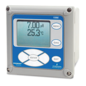
1066 Transmitter Instruction Manual Section 6: Display & Operation LIQ_MAN_1066-P-FF September 2013 Section 6: Display and Operation User Interface The 1066 has a large display which shows the measurement readout and temperature in large digits and up to four addi- Calibrate tional process variables or diagnostic parameters concur- rently. -
Page 34: Main Display
Section 6: Display & Operation 1066 Transmitter Instruction Manual September 2013 LIQ_MAN_1066-P-FF 3. Enter or edit numeric values 4. Move the cursor to the right or left 5. Select measurement units during operations Main Display The 1066 displays the primary measurement value and temperature, and up to four secondary measurement values, a fault and warning banner, and a digital communications icon. -
Page 35: Formatting The Main Display
1066 Transmitter Instruction Manual Section 6: Display & Operation LIQ_MAN_1066-P-FF September 2013 Formatting the Main Display The main display screen can be programmed with the Transducer Block in the Automatic Mode as follows: 1. Press MENU 2. Scroll down to Display. Press ENTER. 3. - Page 36 Section 6: Display & Operation 1066 Transmitter Instruction Manual September 2013 LIQ_MAN_1066-P-FF This page left blank intentionally Display and Operation...
-
Page 37: Section 7: Programming Measurements/ Ph Measurement Programming
1066 Transmitter Instruction Manual Section 7: Programming Measurements LIQ_MAN_1066-P-FF September 2013 Section 7: Programming Measurements / pH Measurement Programming This section outlines how the various configuration parameters affect the measurement, and how to access them. Note: Accessing the Program menu places the Transducer Block in the Out of Service Mode. This will cause all measurement channels to have a BAD status (Bad: Out of Service), which can affect the control system. -
Page 38: Measurement
Section 7: Programming Measurements 1066 Transmitter Instruction Manual September 2013 LIQ_MAN_1066-P-FF The second item in the Temperature menu selects the source of the temperature to be used for temperature compensation. These are: • Auto/Sensor: This selection uses the temperature element in the pH sensor as the source for temperature compensation, and is most commonly used. -
Page 39: Resolution (Ph Only)
1066 Transmitter Instruction Manual Section 7: Programming Measurements LIQ_MAN_1066-P-FF September 2013 Selecting Sol’n Temp Corr provides the following choices for solution temperature correction: • Ultra Pure Water: Provide solution temperature compensation for very low conductivity water approaching pure water. • High pH: Provide solution temperature compensation for alkaline solution, which exhibit a characteristic pH change with temperature. -
Page 40: Reference Z
Section 7: Programming Measurements 1066 Transmitter Instruction Manual September 2013 LIQ_MAN_1066-P-FF 7.3.7 Reference Z This parameter is used to change the input of the 1066 to receive the millivolt signal from a sensor having, by design, high reference impedance. The default reference impedance setting is the Low which accommodates reference impedances up to 1,000 kohm (1 Mohm). -
Page 41: Fieldbus Analog Input And Output Block Configuration
1066 Transmitter Instruction Manual Section 7: Programming Measurements LIQ_MAN_1066-P-FF September 2013 Fieldbus Analog Input and Output Block Configuration All Fieldbus applications use at least one AI (Analog Input) Block to publish the Primary Value (pH, ORP, or Redox) to the bus. Other applications might require temperature, reference impedance, or glass electrode impedance to also be published to the bus. -
Page 42: Fieldbus Analog Output Block Configuration
Section 7: Programming Measurements 1066 Transmitter Instruction Manual September 2013 LIQ_MAN_1066-P-FF • If Fieldbus Temperature (Auto/Fieldbus) is used, Channel 2 will be the same as the tempera- ture from the bus. • If Manual Temperature (Manual) is used, Channel 2 will be the Manual Temperature. It usually only makes sense to configure an AI Block for Temperature if Auto/Sensor temperature compensation is being used. - Page 43 1066 Transmitter Instruction Manual Section 7: Programming Measurements LIQ_MAN_1066-P-FF September 2013 3. Check that the temperature units of the temperature on the bus match the temperature units used by the 1066pH. 4. Using a Fieldbus configurator link the temperature measurement output to the CAS_IN of the 1066ph AO Block.
- Page 44 Section 7: Programming Measurements 1066 Transmitter Instruction Manual September 2013 LIQ_MAN_1066-P-FF This page left blank intentionally Programming Measurements...
-
Page 45: Section 8: Calibration
1066 Transmitter Instruction Manual Section 8: Calibration LIQ_MAN_1066-P-FF September 2013 Section 8: Calibration Introduction New sensors must be calibrated before use. Recalibration is also necessary at frequencies deter- mined by the nature of the application, and experience. The following calibration routines are available are: •... -
Page 46: Minimum / Maximum Slope And Reference Offset Setup
Section 8: Calibration 1066 Transmitter Instruction Manual September 2013 LIQ_MAN_1066-P-FF The setup parameters are as follows: • Buffer: Selects the buffer type from the list of standard buffers: – Standard: (Includes NIST buffers and 7.01 pH buffer) – DIN 19267 –... -
Page 47: Calibration Procedures
1066 Transmitter Instruction Manual Section 8: Calibration LIQ_MAN_1066-P-FF September 2013 8.1.4 Calibration Procedures 8.1.4.1 Calibration When Using Temperature from Fieldbus For an accurate pH measurement, the temperature of the pH sensor must be accurately measured. This is also true when performing a calibration because an inaccurate pH measurement during cal- ibration will result in errors in the calibration, which might not be outside the slope and reference offset limits, and can go undetected. - Page 48 Section 8: Calibration 1066 Transmitter Instruction Manual September 2013 LIQ_MAN_1066-P-FF Prompt: Buffer 2; recognized pH of Buffer 2; Press Enter to store Buffer 1 pH, or if the value displayed is not the pH value of the buffer being used, use the Up and Down Arrow Keys to move to the next higher or lower pH value. Prompt: Calibration in Progress, please wait If the slope is within the min/max slope limits and the reference offset if with the offset limits, the new slope and reference offset values are shown and the calibration is completed.
- Page 49 1066 Transmitter Instruction Manual Section 8: Calibration LIQ_MAN_1066-P-FF September 2013 during Manual calibration, the temperature of the buffer solution being used should be noted, and the pH value of the buffer at that temperature (usually printed on the buffer bottle) should be used.
-
Page 50: Temperature Calibration
Section 8: Calibration 1066 Transmitter Instruction Manual September 2013 LIQ_MAN_1066-P-FF Entering Calibration Constant(s) from a Pre-Calibrated Sensor 8.1.4.5 After calibrating a pH or ORP sensor in the laboratory or shop, record the Slope and Offset for pH sensors or the Offset for ORP sensors. Navigate to standardization: Main menu →... - Page 51 1066 Transmitter Instruction Manual Section 8: Calibration LIQ_MAN_1066-P-FF September 2013 Note on Using Temperature from Fieldbus for Temperature Compensation: If the pH sensor being used has a temperature element (RTD), it is useful to calibrate its temperature measurement even though temperature from Fieldbus will be used for temperature compensation. Calibrating the pH sensor temperature measurement allows the temperature measurement from the sensor to be accurate when doing buffer calibrations or standardizations with the pH sensor out of the process.
- Page 52 Section 8: Calibration 1066 Transmitter Instruction Manual September 2013 LIQ_MAN_1066-P-FF This page left blank intentionally Calibration...
-
Page 53: Introduction
1066 Transmitter Instruction Manual Section 9: Diagnostics LIQ_MAN_1066-P-FF September 2013 Section 9: Diagnostics Introduction There are a number of diagnostic messages to alert the user to issues with the transmitter, sensor, or a failed calibration. Most of these require no configuration. Only the minimum/maximum slope and reference offset calibrations, in the previous section can be configured, and the sensor impedance diagnostics. -
Page 54: Setting Up Sensor Impedance Diagnostics
Section 9: Diagnostics 1066 Transmitter Instruction Manual September 2013 LIQ_MAN_1066-P-FF Reference Electrode Impedance Diagnostics 9.2.1.2 In a pH or ORP measurement, the reference electrode serves two purposes. The first is to provide a know potential (millivolts) at any given temperature, by using a silver chloride wire (AgCl) in a potassium chloride solution (KCl). -
Page 55: Diagnostics Alarms
1066 Transmitter Instruction Manual Section 9: Diagnostics LIQ_MAN_1066-P-FF September 2013 9.2.2.5 Ref Fault High This parameter sets the high reference electrode impedance fault limit up to 999 kohm. The default is 500 kohm. Diagnostics Alarms Diagnostic alarms, in general, alert users to sensor or transmitter problems. In addition, there are notifications of events, such as calibrations, which serve to provide useful information to plant and batch historians that calibrations have, in fact, been done. - Page 56 Section 9: Diagnostics 1066 Transmitter Instruction Manual September 2013 LIQ_MAN_1066-P-FF TABLE 9-1. Alert List Alerts Recommended Action Help Temperature Check the temperature There is an open or short in the RTD measuring circuit. The temperature value will appear very Error sensor and its wiriing.
- Page 57 1066 Transmitter Instruction Manual Section 9: Diagnostics LIQ_MAN_1066-P-FF September 2013 TABLE 9-1. Alert List continued Alerts Recommended Action Help pH Voltage Too Check the pH sensor The indicated pH is outside the range of the transmitter due to miswiring, or a major failure of High and its wiring.
-
Page 58: Field Diagnostics
Section 9: Diagnostics 1066 Transmitter Instruction Manual September 2013 LIQ_MAN_1066-P-FF The status of all the measured parameters of the 1066pH can be viewed quickly using Fieldbus: FIGURE 9-2. Good Measurement Status FIGURE 9-3. Bad Measurement Status Field Diagnostics As outline previously, the diagnostic alerts provided by the 1066pH are presented on the local dis- play and by Fieldbus, and affect the status of measurements. -
Page 59: Alarm Categories (Namur Ne-107)
1066 Transmitter Instruction Manual Section 9: Diagnostics LIQ_MAN_1066-P-FF September 2013 9.4.1 Alarm Categories (NAMUR NE-107) Field Diagnostics uses the classification of NAMUR NE-107, which are defined as follows: • Failure – Output signal invalid due to malfunction in the field device or its peripherals e.g. a broken glass electrode. - Page 60 Section 9: Diagnostics 1066 Transmitter Instruction Manual September 2013 LIQ_MAN_1066-P-FF • Mask – Suppresses the broadcast of any alarm or alarms to the host • Simulate – Allows alarms to be manually simulated; requires the simulate jumper to be in place on the 1066pH circuit board.
-
Page 61: Section 10: Fieldbus Specifications
1066 Transmitter Instruction Manual Section 10: Fieldbus Specifications LIQ_MAN_1066-P-FF September 2013 Section 10: Fieldbus Specifications 10.1 General Specifications Model: 1066-P-FF pH Fieldbus Transmitter Type: pH/ORP/Redox Transmitter Device ITK Profile: 6 (Released for ITK 6.0.0 / 6.0.1) Manufacturer Identification (MANUFAC_ID): 0x524149 Device Type (DEV_TYPE): 0x4089 Device Revision (DEV_REV): 0x01 Physical Layer Profiles: 111,113,511... -
Page 62: Resource Block
The Resource Block parameter table is shown in Table 10-1 on the following pages. Parameters 1 through 41 are standard Fieldbus Resource Block parameters; parameters 42 through 66 support Field Diagnostics. Parameters 67 through 92 are Emerson device specific parameters which sup- port Common Software Download and PlantWeb Alerts. -
Page 63: Simulation Of The Primary Variable
1066 Transmitter Instruction Manual Section 10: Fieldbus Specifications LIQ_MAN_1066-P-FF September 2013 • Manual Mode – All parameters used for configuring and performing calibration including writing to cali- bration constants (pH slope and reference offset) can be written to – Temperature Compensation Type and Manual Temperature which allows these parame- ters to be changed during calibration routines and methods –... -
Page 64: Arithmetic Function Block
Section 10: Fieldbus Specifications 1066 Transmitter Instruction Manual September 2013 LIQ_MAN_1066-P-FF Arithmetic Function Block 10.7 Can do useful calculations: • Using conductivity ratios to calculate Reverse Osmosis Efficiency or Steam Quality. • Calculate mass flow from concentration and mass or volumetric flow. Integrator Function Block 10.8 Can totalize:... -
Page 65: Control Selector Function Block
Fieldbus EDD and DTM Download Sites 10.14 • Basic DD files: www.fieldbus.org • AMS Installation and DTM Files: www.assetweb.com • 475 and 375 Communicator Support: – File download: www.fieldcommunicator.com – Local Emerson Process Service Group or National Response Center (1-800-654-7768) Fieldbus Specifications... - Page 66 Section 10: Fieldbus Specifications 1066 Transmitter Instruction Manual September 2013 LIQ_MAN_1066-P-FF TABLE 10-1. Resource Block Parameters Parameter Index Description Mnemonic ST_REV The revision level of the static data associated with the function block. To support tracking changes in static parameter attributes, the associated block’s static revision parameter will be incremented each time a static parameter attribute value is changed.
- Page 67 1066 Transmitter Instruction Manual Section 10: Fieldbus Specifications LIQ_MAN_1066-P-FF September 2013 TABLE 10-1. Resource Block Parameters continued Parameter Index Description Mnemonic BLOCK_ALM The block alarm is used for all configuration, hardware, connection failure or system problems in the block. The cause of the alert is entered in the subcode field. The first alert to become active will set the Active status in the Status attribute.
- Page 68 Section 10: Fieldbus Specifications 1066 Transmitter Instruction Manual September 2013 LIQ_MAN_1066-P-FF TABLE 10-1. Resource Block Parameters continued Parameter Index Description Mnemonic FD_CHECK_PRI This parameter allows the user to specify the priority of this alarm category. FD_SIMULATE This parameter allows the conditions to be manually supplied when simulation is enabled. When simulation is disabled both the diagnostic simulate value and the diagnostic value track the actual conditions.
- Page 69 1066 Transmitter Instruction Manual Section 10: Fieldbus Specifications LIQ_MAN_1066-P-FF September 2013 TABLE 10-1. Resource Block Parameters continued Parameter Index Description Mnemonic ADVISE_PRI Designates the alarming priority of the ADVISE_ALM. ADVISE_ENABLE Enabled ADVISE_ALM alarm conditions. Corresponds bit for bit to the ADVISE_ACTIVE. A bit on means that the corresponding alarm condition is enabled and will be detected.
- Page 70 Section 10: Fieldbus Specifications 1066 Transmitter Instruction Manual September 2013 LIQ_MAN_1066-P-FF TABLE 10-2. Transducer Block Parameters continued Units/ Write RO or PARAMETER NAME Description VALID RANGE Enumerations Mode A directory that specifies the number and TRANSDUCER_ starting indices of the transducers in the DIRECTORY transducer block.
- Page 71 1066 Transmitter Instruction Manual Section 10: Fieldbus Specifications LIQ_MAN_1066-P-FF September 2013 TABLE 10-2. Transducer Block Parameters continued Write RO or PARAMETER NAME Description VALID RANGE UNITS/ Enumerations Mode ISOPOTENTIAL_PH Sensor isopotential 0 to 14 0 to 14 pH 1 = Single point 2 = Dual point SENSOR_CAL_METHOD Sensor calibration method 1 to 3...
- Page 72 Section 10: Fieldbus Specifications 1066 Transmitter Instruction Manual September 2013 LIQ_MAN_1066-P-FF TABLE 10-2. Transducer Block Parameters continued VALID RO or PARAMETER NAME Description UNITS/ Enumerations Write Mode RANGE Bit 15: Ref Z mode 0=Low,1=High Bit 13: Pre-amp location(Read only in case of smart pH sensor) FLAG_BITS Configuration Flags...
- Page 73 1066 Transmitter Instruction Manual Section 10: Fieldbus Specifications LIQ_MAN_1066-P-FF September 2013 TABLE 10-2. Transducer Block Parameters continued RO or PARAMETER NAME Description VALID RANGE UNITS/ Enumerations Write Mode 1 = CPU Error 1 = CPU Error 2 = Factory Data 2 = Factory Data Error Error...
- Page 74 Section 10: Fieldbus Specifications 1066 Transmitter Instruction Manual September 2013 LIQ_MAN_1066-P-FF TABLE 10-2. Transducer Block Parameters continued VALID Write RO or PARAMETER NAME Description UNITS/ Enumerations RANGE Mode CALIBRATION_HISTORY_1 1 CAL_HISTORY_RUN_TIME Run-time 0 to 40000 0 = none 3 = 1pt standardize 2 CAL_HISTORY_METHOD Method 1= 2-pt auto-buffer 4 = manual entry...
-
Page 75: General
1066 Transmitter Instruction Manual Section 11: Return of Material LIQ_MAN_1066-P-FF September 2013 Section 11: Return of Material 11.1 General To expedite the repair and return of instruments, proper communication between the customer and the factory is important. Before returning a product for repair, call 1-949-757-8500 for a Return Materials Authorization (RMA) number. -
Page 76: September
EC Declaration of Conformity 1066 Transmitter Instruction Manual September 2013 LIQ_MAN_1066-P-FF EC Delaration of Conformity... - Page 77 1066 Transmitter Instruction Manual EC Declaration of Conformity LIQ_MAN_1066-P-FF September 2013 EC Delaration of Conformity...
- Page 78 EC Declaration of Conformity 1066 Transmitter Instruction Manual September 2013 LIQ_MAN_1066-P-FF Device Registration...
- Page 79 1066 Transmitter Instruction Manual LIQ_MAN_1066-P-FF September 2013 This page left blank intentionally...
- Page 80 Emerson Process Management ©2013 Rosemount Analytical, Inc. All rights reserved. The Emerson logo is a trademark and service mark of Emerson Electric Co. Brand name is a mark 2400 Barranca Parkway of one of the Emerson Process Management family of companies. All other marks are the property Irvine, CA 92606 USA of their respective owners.
Need help?
Do you have a question about the Rosemount 1066 and is the answer not in the manual?
Questions and answers