
Related Manuals for YOKOGAWA CW140


Summary of Contents for YOKOGAWA CW140
- Page 1 CW140 User's CLAMP-ON POWER METER Manual IM CW140-E IM CW140-E 3rd Edition July 2001 (YK)
- Page 3 Introduction Thank you for purchasing our CW140 Clamp-on Power Meter. This User’s manual explains the functions of the CW140, as well as its operating methods and handling precautions. Before using the CW140, read this manual thoroughly to ensure correct use of the instrument.
- Page 4 Make sure that the package contains all the accessories listed below and that they are all free from any damage. Product Name Part Number Qty Remarks 1. AC adapter for power supply 788011 1 set Yokogawa’s AC adapter 2. AA alkaline dry cells — (alkaline batteries) 3. Voltage probes 91007 Supplied together with two sets of ring markers of three different colors.
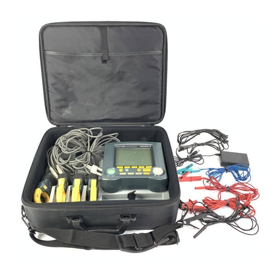
- Page 5 It is advisable that the packing box be stored, as it is useful when you transport the instrument. Housing CW140 Main Unit and Accessories An optional carrying case can accommodate the CW140 main unit with its current-sensing clamp-on probes and voltage probes connected to the unit.
-
Page 6: Precautions For Safe Use Of The Instrument
If you use the instrument in any other way than instructed in this manual, the instrument’s protective measures may be impaired. Yokogawa M&C Corporation is by no means liable for any damage resulting from use of the instrument in contradiction to these cautionary notes. - Page 7 If the power cord is damaged, contact the vendor from which you purchased the instrument. See page 2 for information on the AC adapter that is necessary when ordering a replacement power cord. IM CW140-E...
-
Page 8: Table Of Contents
Chapter 8. Instant Measure Mode ................ 8-1 Detailed View of Data Items on Instant Measure Mode Screen ....8-1 Working with the Function Keys ..............8-4 Expanded View of Data Items on Instant Measure Mode Screen ....8-5 IM CW140-E... - Page 9 Event Input ....................14-9 Chapter 15. RS-232C Communication Function ..........15-1 15.1 RS-232C Interface Specifications ............. 15-1 15.2 Connecting CW140 through RS-232C Interface ........15-2 15.3 Handshake Methods ................. 15-4 15.4 Matching the Data Format ................. 15-7 Chapter 16. In the Event of a Power Failure ............. 16-1 16.1...
- Page 10 19.2 Specifications of Current Clamps ............19-15 Appendix ......................App1-1 Appendix 1 Block Diagram of CW140 Main Unit ..........App1-1 Appendix 2. Communication Commands ............App2-1 Appendix 3. Explanation of Data Item to be Saved/Printed ......App3-1 Appendix 4. Terminology .................. App4-1 Appendix 5.
-
Page 11: Appendix
CW140 can measure and analyze a wide variety of parameters related to electric power. This section explains the features of the CW140 and shows a schematic diagram representing the functions of the CW140. It also explains the screen views (i.e., measuring objects) presented by each measurement mode of the CW140. -
Page 12: Auxiliary Functions
Hold of on-screen readings NiMH battery recharging Event input function LCD contrast (Section 14.3) Floppy disk drive unit LCD backlight (connected externally) Beep (confirmation of key operation) (Section 17.2) Key locking Power-saving mode System reset Low battery indicator Testing backup batteries IM CW140-E... - Page 13 (The CW140 does not support the Harmonics Measure mode when wired to 2-system load.) NOTE The CW140 can show a screen of instantaneous values whether it is in the Electric Energy Mea- sure mode or the Demand Measure mode. IM CW140-E...
-
Page 15: Chapter 2. Components, Their Use And Overrange, And Error Indications
<Side View> <Front View> INPUT / OUTPUT CLAMP ON POWER METER AC adapter jack Battery charge LED indicator Power (for optional switch NiMH battery) ENTER START LIGHT LOCK &STOP TOP MENU 65 (2.56) 206 (8.11) Unit: mm (approx. inches) IM CW140-E... -
Page 16: Operation And Functions Keys
Backlight key Turns on/off the backlight. LIGHT Holding this key down for more than 3 seconds places the CW140 in a key lock state. To cancel the state, hold this key down again for more than 3 seconds. Watt-hour key Allows you to measure electric energy easily without selecting the Electric Energy Measure mode from the TOP MENU screen. -
Page 17: Connecting Input Signals To Be Measured And External Input Terminals
External control input terminals: Receive START/STOP signals informing of the start and end of logging, integration or demand measurement. D/A output terminals: Terminals for D/A output (not available if the CW140 is not equipped with a D/A output option). IM CW140-E... - Page 18 • The CW140 can be connect to a maximum of four voltage input probes or four current-sensing clamps. Do not connect any probe or clamp that is not necessary for measurement.
- Page 19 • Do not apply voltages outside the allowable input voltage range (-0.5 to 5.5 V), otherwise the input circuit may be damaged. • When wiring the CW140, be careful not to mistake an input terminal for an output terminal. Applicable Signal Wires Standard wire: φ1.0 single-core wire (AWG18) or 0.75 mm...
-
Page 20: Overrange And Other Marks Shown During Measurement
WARNING The CW140 shows an overrange mark under the maximum range only if the input level exceeds the maximum allowable input level. Do not apply any input level higher than the maximum allow- able input level. - Page 21 Indications When the Measured Value Is Too Small If either a voltage or current input level is below 0.4% of the rated range, the CW140 gives the readings noted below. If a fixed range is used, step down the range.
- Page 22 Appears when display hold is enabled. Appears when a current overrange occurs. Appears when a voltage overrange occurs. Appears when the CW140 is configured so that data is stored in internal memory. Appears when the CW140 is configured so that data is stored on a floppy disk.
-
Page 23: Chapter 3. Precautions For Safe Measurement
The LCD backlight lasts a approximately 10,000 hours when kept turned on at room temperature. If it is used longer than that period, the brightness may drastically decrease. If this occurs, the backlight needs to be replaced. Contact the vendor from which you purchased the instrument. IM CW140-E... - Page 24 CT. • If dust or any other foreign matter gets in the clamping CT, do not shut the clamping cores tight. First remove the dust and then make sure the clamping cores on both sides close smoothly. IM CW140-E...
-
Page 25: Installation Procedure
• close to such a noise source as high-voltage equipment or a motive power supply; • exposed to a relatively large amount of lampblack, steam, dust or corrosive gas; • exposed to frequent mechanical vibration; • close to a source of strong electromagnetic fields; or • unstable. IM CW140-E... -
Page 26: Precautions For Wiring The Circuit Under Test
• Do not use any probes or clamps other than those voltage input probes or dedicated clamps supplied together with the CW140. • Do not use a clamp with any non-insulated conductors. After wiring the CW140, it is necessary to perform setting/operation for the wiring method using the WIRING key. SEE ALSO Section 7.1, "Wiring,"... -
Page 27: Diagrams Of Basic Wiring
Current input terminals N V1 On-screen symbol In the case of a current-sensing clamp, the symbol of a current input terminal shown on the CW140 main unit differs from that shown on the display, as indicated in the figures above. IM CW140-E... - Page 28 When connecting the current-sensing clamp, make sure the following polarities and clamp position are correctly identified. 1 When connecting to Power supply side (SOURCE) the CW140 main unit: Conductor cable H and L polarities 2 The clamp should be positioned in the...
- Page 29 1φ φ φ φ φ 3W× × × × × 2 Voltage input terminals Current input terminals N V1 On-screen symbol I2-1 I1-2 I2-2 3φ φ φ φ φ 3W× × × × × 2 Voltage input terminals Current input terminals N V1 On-screen symbol I3-1 I1-2 I3-2 IM CW140-E...
-
Page 30: Wiring The Circuit Under Test Using External Vt/Ct
Section 7.7, "Scaling Function," for details on how to use VT/CT. • The lowest current range of the CW140 main unit itself is 20 A on full scale and the accuracy also depends on this value. Note therefore that if a CT is used and its secondary output is too small when compared with 20 A, then the error ratio will become higher. -
Page 31: Connecting A Power Supply And Turning It On/Off
3.6 Connecting a Power Supply and Turning It On/Off The CW140 can be operated with the following three types of power supply. • Six AA-size alkaline batteries • AC power supply through an AC adapter (standard accessory) Part number: 788011 Yokogawa’s AC adapter... - Page 32 • If the voltage of an alkaline battery falls below a given level, the mark appears in the upper- right corner of the display (low-battery state). If you continue to operate the CW140 in this state, the meter automatically turns off.
- Page 33 • Before connecting the power cord, also make sure the power switch on the CW140 is turned off. • If the CW140 is not to be used for a prolonged period, disconnect the power cord from the outlet. • Do not use any other AC adapter than the one (part number: 788011) dedicated to the CW140.
- Page 34 AC-input side (for connection to the AC power outlet) 3. Connect the AC adapter plug to the AC adapter jack of the CW140. 4. Connect the plug of the power cord supplied together with the AC adapter to the power supply connector of the AC adapter.
- Page 35 • Do not immerse the battery pack in water or make it wet, as this may cause it to heat up or rust, as well as lead to a loss of functions. • If the battery pack is not used for a prolonged period, remove it from the CW140 main unit and store it in the following environment: Storage period of 1 year or less: Temperature of –20°C to 35°C...
- Page 36 Finally, make sure both connectors are precisely mated with each other. 5. Push down the lock switch on one side of the CW140 to fix the battery holder in place. (The label changes to "∆FREE".) SEE ALSO The figure given below.
- Page 37 When recharging is complete, the LED indicator flashes rapidly. NOTE If the power switch on the CW140 is turned on, the NiMH battery pack is not recharged. In that case, the CW140 is powered from the AC adapter. 3-15...
- Page 38 3.6 Connecting a Power Supply and Turning It On/Off • The CW140 is in a wait-for-recharge state when the LED indicator is flashing slowly (lit for approxi- mately one second when on). The meter falls into this state when: • the ambient temperature is outside the range from 10°C to 35°C;...
- Page 39 3.6 Connecting a Power Supply and Turning It On/Off Startup Screen When you turn on the power switch on the CW140 main unit, the display successively presents the screens described in paragraphs (1) and (2) below. Model Name Screen The CW140 first shows such a screen as illustrated on the right, then performs a self-test.
-
Page 40: Performing Measurements With Higher Precision
If you move the CW140 from an area of low temperature and humidity to an area of high humidity and temperature or if there is a sudden change in the ambient temperature, condensation may occur in the meter. -
Page 41: Chapter 4. Basic Operation Flow And Top Menu Screen
Supply power to CW140 NiMH battely pack <Section 3.6> Turn on power of CW140 Opening message When you use the CW140 with Go to the Top Menu for first-time the most recently used settings. use after delivery. Same status as last time... -
Page 42: Top Menu Screen
T O P M E N U Retrieves the Top Menu. Using the Cursor key, select the desired mode. (It becomes highlighted.) The selected mode screen appears. You can also use the key to select the electric energy mode. IM CW140-E... -
Page 43: Chapter 5. System Settings
Press the F5 key, to change the next screen. Using the function keys, change the settings on screen 2/2. Applies the changes you made to the settings. Press the escape key to cancel all the changes you made. IM CW140-E... - Page 44 Section 17.1, Adjusts LCD's contrast (1 to 8). "Auxiliary Functions" Input values. – Beep Section 17.1, ON (Beeps for every key action) "Auxiliary OFF (Not used) Functions" Power-saving Section 17.1, ON (Used) mode (LCD) "Auxiliary OFF (Not used) Functions" IM CW140-E...
- Page 45 Selects the item to be changed. Year Month Time Language Section 17.1, English (CHANGE) Press this key. "Auxiliary Functions" English Francais Deutsch Italiano Español Use the cursor key to select the language. Press this key to confirm the selection. IM CW140-E...
-
Page 46: System Reset
If system reset has been executed, the following message appears: System reset executed. All parameters are initialized to default. Enter key: OK Retrieves the Top Menu. IM CW140-E... -
Page 47: Chapter 6. File Handling
Memory format: Formats internal memory. Data copy: Copies a file in internal memory to a floppy disk. Program update: Refer to NOTE on page 6-3. To use the floppy disk items, an optional floppy disk drive is required. IM CW140-E... - Page 48 Format FD. (_MB) ENTER key: YES ESC key: NO Now formatting. (_MB) Format complete. (_MB) ENTER key: OK Memory format Format internal memory? Formats memory. ENTER key: YES ESC key: NO Now formatting Format complete. ENTER key: OK IM CW140-E...
- Page 49 A message requesting confirmation appears. To select all files, press the key. To cancel one file, press the key. To cancel all files, press the key. NOTE Do not execute program update item. It is only for maintenance. IM CW140-E...
-
Page 50: File Name And File Attribute
SEE ALSO Section 6.3, “Entering a File Name” for more information on how to enter a file name. If you do not specify any file name, the CW140 gives the file a default name as follows. Example: DINSxxx. -
Page 51: Entering A File Name
(INPUT): Places each selected character in the file name field. The cursor moves to the right. Repeat step above for up to 8 characters. : Press this key to confirm the file name. File name field Character selection area IM CW140-E... - Page 52 Same file name already exists. Overwrite? Enter key: YES ESC key: NO : Press this key to overwrite the existing file. : Press this key to cancel. If you do not want to overwrite the existing file, enter another file name. IM CW140-E...
-
Page 53: Chapter 7. Common Functions Of All Modes
I1-2 (CH3), I2-2 (CH4) 3φ3W×2 Load 1 I1-1 (CH1), I3-1 (CH2) Load 2 I1-2 (CH3), I3-2 (CH4) The indications I1 to I3 correspond to the wiring displayed on the screen. The indications CH1 to CH4 correspond to the current input terminals. IM CW140-E... - Page 54 TIME”, is not at zero, or in demand mode and the remaining time, “DEMAND REST TIME”, is not at zero. • Be sure to press the key for three seconds or more and then clear the integrated value before changing the type of wiring. IM CW140-E...
-
Page 55: Checking Wiring
• Voltage and current ranges are set to AUTO while wiring is being checked and will retrieve the preset value after checking. * Frequency source The frequency source indicates the source selected for measuring the frequency of voltage inputs (V1 to V3) and current inputs (CH1 to CH4) in the system settings. IM CW140-E... - Page 56 Press this key to view the check list. (WIRE FIG): Press this key to view the wiring diagram for the selected power line type. (END): Press this key to quit the wiring check and return to the measurement screen. IM CW140-E...
- Page 57 1.2 kHz or more. NOTE As the CW140 judges wiring according to the conditions listed above, there may be some cases where the check result of correct wiring is NG, and vice versa. If measurement values appear erroneous, check these conditions and re-check the wiring.
-
Page 58: Ranges And Number Of Digits
Selecting between clamp type A, B and C can be made on the last page for each mode or the system setting screen. : Clamp A (20-200 A) : Clamp B (200-1000 A) : Clamp C (50-500 A) The default setting is Clamp A. IM CW140-E... - Page 59 In this case, change the range to a fixed value and restart measurement. When in AUTO range measurement, voltage and current ranges change, which may result in different ranges for the same power or measured value. IM CW140-E...
- Page 60 • For reactive and apparent power, the same table applies, however, the units of measurement are different. For reactive power: kVar For apparent power: kVA • If the VT or PT ratio is set to a value other than 1, multiply each value in the table by the ratio. IM CW140-E...
- Page 61 1 to 9.999 MA 9.999 MA 10 to 99.99 MA 99.99 MA Frequency Input frequency Position of decimal point and unit of measurement 45 to 99.99 Hz 99.99 Hz 100 to 999.9 Hz 999.9 Hz 1 to 1.2 kHz 1.200 kHz IM CW140-E...
- Page 62 * : When Demand measurement mode, Electric energy of period is obtained by multiplying Demand period time (unit: hours)additionally. For electric energy, if the measured value exceeds the maximum displayable value, the display value will be reset to zero (e.g. 999.999 kWh → 0.000 kWh). 7-10 IM CW140-E...
- Page 63 • Switching is performed depending on the largest input among the voltage inputs V1, V2, and V3. The selected range will be applied to all inputs. • Switching is performed depending on the largest input among the current inputs CH1 to CH4. The selected range will be applied to all inputs. 7-11 IM CW140-E...
- Page 64 7.3 Ranges and Number of Digits Switching voltage ranges in AUTO range (RMS) Voltage range 600V 600V 180V 300V 330V 150V 165V 100V 200V 300V 400V 500V 600V Input voltage To upper range To lower range 7-12 IM CW140-E...
- Page 65 200A 400A 600A 800A 1000A Input current Clamp C : 50A/100A/200A/500A (RMS) Current range 500A 550A 150A 200A 220A 110A 100A 100A 200A 300A 400A 500A Input current During switching, the value "----" will be temporarily displayed. 7-13 IM CW140-E...
-
Page 66: Sampling Frequencies And Integration Periods
The voltage and current RMS, power, and reactive power (when only the reactive power method is used) values are calculated during the integration period. Example: Frequency (Hz) Integration period (msec) Number of sine waves 116.67 102.5 7-14 IM CW140-E... - Page 67 PLL. Two periods' worth of samples (i.e., 512 samples) are used to perform the calculation of harmonic parameters. In the examples shown above, the waves are sine waves (50 Hz) generated by using the voltage input 7-15 IM CW140-E...
-
Page 68: Frequency Measurement And Low-Pass Filters
(CHANGE): Press this key to display selectable items (for wiring) in the center of the screen. FREQUENCY SOURDE SETTING Using the Cursor key, select the desired item. Confirms the selection. Confirms the settings. Return to the measurement screen. 7-16 IM CW140-E... - Page 69 1/2 of the system setting screen or on the last page of the setup screen in each measurement mode by pressing the key. The default value is OFF. Using the Cursor key, select the item “Low-pass filter.” Press either key to select the desired setting. Confirms the selection. 7-17 IM CW140-E...
-
Page 70: Averaging Function
7.6 Averaging Function As power in the measured lines may greatly fluctuate, the CW140 is facilitated with a function to calculate the moving average. The averaging function can be set to on or off on page 1/2 of the system setting screen or on the last page of the setup screen in each measurement mode. -
Page 71: Scaling Function (Vt/Ct)
For the settings of VT and CT ratios, see page 1/2 of the system setting screen, p. 5-2, or the last page of setup screen in each measurement mode: Instant mode: p. 8-13 Electric energy mode: p. 9-11 Demand mode: p. 11-12 Harmonics mode: p. 12-12 7-19 IM CW140-E... -
Page 73: Chapter 8. Instant Measure Mode
Chapter 8. Instant Measure Mode 8.1 Detailed View of Data Items on Instant Measure Mode Screen In Instant Measure mode, the CW140 measures and calculates the data items listed below and displays the results. Display of Measured/Calculated Values Voltage (rms value) (V) - Page 74 The Instant Measure Mode screen appears. Display of measured/calculated values Display of setup conditions Three-phase Unbalance Factor This data item is shown only when a three-phase wiring method is applied. The frequency range is specified as 45 to 440 Hz. IM CW140-E...
- Page 75 3/3 of the screen. The default value is V1. Now change the setting and press the (CHANGE) key. FREQUENCY SOURCE Press the key. SEE ALSO Page 7-16, for details on the setting of the data item "Frequency Source." IM CW140-E...
-
Page 76: Working With The Function Keys
SETUP data items). (LOAD_CHG): Switches between Load 1 and Load 2 (if the wiring is for a 2-load system). (HOLD): Holds the on-screen readings. Holding: The screen shows the mark in the upper-middle area of the display. IM CW140-E... -
Page 77: Expanded View Of Data Items On Instant Measure Mode Screen
Press the (CHANGE) key to change the data item. DISP. ITEM V1 V2 Press the to cancel the procedure of change. Use the key to select a data item to be displayed. Press the key to confirm your selection. IM CW140-E... - Page 78 • The choice of data items V1 to V3 and I1 to I3 varies depending on the type of wiring. • If the CW140 is wired to a 2-load system, the same data item is selected for both loads. • If you change the wiring type and the selected data item is not identified as an actual input on the wiring, the default data item is selected.
-
Page 79: Logging In Instant Measure Mode
You can set the interval from the starting to the ending time, in 10-second increments, to a maximum of 1000 hours. Holding down the (+) or (–) key during input of a value, increases the speed with which the value changes. IM CW140-E... - Page 80 • The changing of settings is not allowed during logging (viewing only). • The setting of a time earlier than the current time is not allowed. In addition, the CW140 shows an error message if, after time setting, the preset starting time of logging has already expired before logging begins.
- Page 81 You are not allowed to set the time interval from the start to the end of logging at a value smaller than the OUTPUT INTERVAL setpoint. If you set such a value, the CW140 shows an error message when you press the key.
-
Page 82: Setup Data Items Of Instant Measure Mode
* Shown only if the logging function is used ("Logging" is set to ON). Number of averaging cycles The "D/A output" setup data item on the Instant Setting screen page 2/3 is visible only if the CW140 is equipped with a D/A output option. - Page 83 • If none of the settings needs to be changed, press the key. The display changes to a measurement screen. • The changing of settings is not allowed when the CW140 is in a stand-by state or is performing logging (only viewing is allowed). 8-11...
- Page 84 "File name and (Only effective AINS XXX.CSV File attribute" if "LOGGING" is 000 to 999 Designated: set to ON) Section 6.3, (CHANGE) : Enters a name of no more than MEMORY/FD "Entering a File 8 alphanumeric characters. Name" 8-12 IM CW140-E...
- Page 85 System Setting screen page 1/2. Consequently, you can change these setup data items of the System Setting screen by pressing the key in Instant Measure mode, rather than by calling the TOP MENU screen and then the System Setting screen. 8-13 IM CW140-E...
- Page 86 : ON-2 (Load 2 only) : ALL (both Loads 1 and 2) : OFF Even if you set data items to be saved/printed, they are not saved/printed if the LOGGING setup data item is set to OFF. 8-14 IM CW140-E...
-
Page 87: Computational Expressions
Lead: – Three-phase Unbalance Factor Vb ×100 % Unbalance foctor = • For 3φ3W Vs = : line-to-line voltages for the 3φ3W. • For 3φ4W In the equations, V for the 3φ3W are substituted with V respectively. 8-15 IM CW140-E... - Page 88 8.6 Computational Expressions Computational Expressions of Instant Measure Mode The CW140 performs the computations summarized below by using the measured values of V, A, W and Q variables. Reactive Power 2 Apparent Power Power Factor Phase Angle (Without reactive power meter method.) 1φ2W...
-
Page 89: Chapter 9. Electric Energy Measure Mode
It also shows information on the start and end of integration in the lower section of the display. Information shown on the display varies depending on whether the CW140 is ready for integration, is performing integration or has finished integration, or how it starts or stops integration. - Page 90 When the value exceeds the maximum displayable value, the display value will be reset to zero (e.g. 999.999 kWh → 0.000 kWh). Display of Instantaneous Values With the key, you can show the measured/calculated values of detailed Instant Measure mode data items (except for the unbalance factor). IM CW140-E...
-
Page 91: Working With The Function Keys
If you clear integrated values, all the readings of electric energy, regenerative energy, lagging reactive energy and leading reactive energy are reset to zero (0). (The reading of the PASSAGE TIME data item is also reset to zero.) IM CW140-E... -
Page 92: Integration In Electric Energy Measure Mode
You can set the interval from the starting to the ending time, in 10-second increments, to a maximum of 1000 hours. Holding down the (+) or (–) key during input of a value, increases the speed with which the value changes. IM CW140-E... - Page 93 • The changing of settings is not allowed during integration (viewing only). • The setting of a time that precedes the current time is not allowed. In addition, the CW140 shows an error message if, after time setting, the preset starting time of integration has expired before integra- tion begins.
- Page 94 You are not allowed to set the time interval from the start to the end of integration at a value smaller than the OUTPUT INTERVAL setpoint. If you set such a value, the CW140 shows an error message when you press the key.
-
Page 95: Setup Data Items Of Electric Energy Measure Mode
Number of averaging cycles * Shown only if "DATA OUTPUT" is set to ON. The "D/A output" setup data item on the Energy Setting screen page 2/3 is visible only if the CW140 is equipped with a D/A output option. - Page 96 • If none of the settings needs to be changed, press the key. The display changes to a measurement screen. • The changing of settings is not allowed when the CW140 is in a stand-by state or is performing integration (only viewing is allowed). IM CW140-E...
- Page 97 System Setting screen page 1/2. Consequently, you can change these setup data items of the System Setting screen by pressing the key in Electric Energy Measure mode, rather than by calling the TOP MENU screen and then the System Setting screen. IM CW140-E...
- Page 98 STANDARD 000.000 0000.00 00000.0 000000 Select the position of decimal point. Confirms the selection. • Unit of measurement Pressing the key shows a screen for selection. Wh kWh MWh GWh Selects the unit of meaurement. Confirms the selection. 9-10 IM CW140-E...
- Page 99 NUMBER OF Section 7.6, OFF: The averaging (+): Cycles through OFF→ 2 → 3 → ... 10 → OFF. AVERAGE "Averaging function is not used. (–): Cycles through OFF→10 → 9 → ... 2 → OFF. Function" 9-11 IM CW140-E...
- Page 100 Active power, reactive power, apparent power, power factor, phase angle, frequency Electric energy Active electric energy, regenerative energy, lagging reactive electric energy, leading reactive electric energy Event input Status H/L of event input The data items "voltage" and "current" take rms values. 9-12 IM CW140-E...
- Page 101 : ON-2 (Load 2 only) : ALL (both Loads 1 and 2) : OFF Even if you set data items to be saved/printed, they are not saved/printed if the DATA OUTPUT setup data item is set to OFF. 9-13 IM CW140-E...
-
Page 103: Chapter 10. Key
LAST CONDITION screen and SETTING CONDITION screens 1 to 4. Each press of the key cycles through the screens, as shown below. LAST CONDITION SETTING SETTING screen CONDITION 1 CONDITION 2 SETTING SETTING CONDITION 4 CONDITION 3 10-1 IM CW140-E... -
Page 104: Simple Electric Energy Measurement With Key
Chapter 9. For details on how to set/ change such settings as the start/end of integration, use the (SETUP) key. SEE ALSO "Setup Data Items of Electric Energy Measure Mode" on pages 9-7 to 9-13, for more information on the setup data items. 10-2 IM CW140-E... - Page 105 ENERGY SET 3/3 screen of the Electric Energy Measure mode. If the selected source is not identified as an actual input on the wiring, the data item defaults to "V1". (If necessary, change this data item when changing the setup data items of the Electric Energy Measure mode.) 10-3 IM CW140-E...
-
Page 106: Event Input
SETTING CONTENTS screen. Symbol Group of Items Voltage Current Power Electric energy Event input SEE ALSO "Data Items to Be Saved/Printed" in the paragraph, "Setup Data Items of Electric Energy Measure Mode," on page 9-12. 10-4 IM CW140-E... -
Page 107: Chapter 11 Demand Measure Mode
Even if the demand ceases during a demand period, the measured value is not numerically affected at all since the CW140 calculates average power by dividing it by a time length. Reference Power You can set a value of reference power between 1 and 1000 kW. (See Section 11.5, "Setup Data Items of Demand Measure Mode.") -
Page 108: Data Items Shown On Demand Measure Mode Screen
11.2 Data Items Shown on Demand Measure Mode Screen In the Demand Measure mode, the interval from the start to the end of demand is segmented into demand periods and the CW140 measures, calculates and indicates the demand. Display of Measured/Calculated Values... - Page 109 It also shows information on the start and end of demand in the lower section of the display. Information shown on the display varies depending on whether the CW140 is ready for demand measurement, is performing demand measurement or has finished demand measurement, or how it starts or stops demand measurement.
-
Page 110: Working With The Function Keys
Clearing: Hold down the key for more than 3 seconds. The following message appears. Measurement data will be cleared. Proceed? ENTER: YES ESC: NO Press the key to clear the integrated values. Press the key to cancel clearance. 11-4 IM CW140-E... -
Page 111: Demand Measurement In Demand Measure Mode
You can set the interval from the starting to the ending time, in 10-second increments, to a maximum of 1000 hours. Holding down the (+) or (–) key during input of a value, increases the speed with which the value changes. 11-5 IM CW140-E... - Page 112 • The changing of settings is not allowed during demand measurement (viewing only). • The setting of a time that precedes the current time is not allowed. In addition, the CW140 shows an error message if, after time setting, the preset starting time of demand measurement has expired before demand measurement begins.
- Page 113 You are not allowed to set the time interval from the start to the end of demand at a value smaller than the DEMAND PERIOD setpoint. If you set such a value, the CW140 shows an error message when you press the key.
-
Page 114: Setup Data Items Of Demand Measure Mode
Number of averaging cycles *Shown only if "Data output" is set to ON. The "D/A output" setup data items on Demand Setting screen page 2/3 are visible only if the CW140 is equipped with a D/A output option. • Show each setting screen with the (NEXT) key, as explained below. - Page 115 • If none of the settings needs to be changed, press the key. The display changes to a measurement screen. • The changing of settings is not allowed when the CW140 is in a stand-by state or is performing demand measurement (only viewing is allowed). 11-9...
- Page 116 System Setting screen page 1/2. Consequently, you can change these setup data items of the System Setting screen by pressing the key in Demand Measure mode, rather than by calling the TOP MENU screen and then the System Setting screen. 11-10 IM CW140-E...
- Page 117 STANDARD 000.000 0000.00 00000.0 000000 Select the position of decimal point. Confirms the selection. • Unit of measurement Pressing the key shows a screen for selection. Wh kWh MWh GWh Selects the unit of meaurement. Confirms the selection. 11-11 IM CW140-E...
- Page 118 NUMBER OF Section 7.6, OFF: The averaging (+): Cycles through OFF→ 2 → 3 → ... 10 → OFF. AVERAGE "Averaging function is not used. (–): Cycles through OFF→10 → 9 → ... 2 → OFF. Function" 11-12 IM CW140-E...
- Page 119 Active power, reactive power, apparent power, power factor, phase angle, frequency Electric energy Active electric energy Demand Power demand, maximum power demand Event input Status H/L of event input The data items "voltage" and "current" take rms values. 11-13 IM CW140-E...
- Page 120 : ON-2 (Load 2 only) : ALL (both Loads 1 and 2) : OFF Even if you set data items to be saved/printed, they are not saved/printed if the DATA OUTPUT setup data item is set to OFF. 11-14 IM CW140-E...
-
Page 121: Chapter 12. Harmonics Measure Mode
(except with input signals from 2-load systems). The data items that can be analyzed are discussed below. In addition to tabular format, the CW140 can show analysis results in graphic format (see Section 12.2). In this chapter, you measure and analyze the 1st- through 13th-order harmonics of such variables (on-screen option of the MEASURE ELEMENT field) as voltage, current or power that you have selected. - Page 122 (DISPLAY) (NO DISPLAY) After selection, press the key to confirm the selection. The display shows a table. Press the key to cancel the selection. The LOGGING data item is shown only when "LOGGING" is set to ON. 12-2 IM CW140-E...
-
Page 123: Showing Graphs In Harmonics Measure Mode
Total (ALL) power (W) Data Items for section Total (ALL) power factor marked (4) above * Value (height) of a bar appropriate for the order of harmonic Fundamental wave frequency (Hz) 12-3 IM CW140-E... - Page 124 (DISPLAY) (NO DISPLAY) After selection, press the key to confirm the selection. The display shows a table. Press the key to cancel the selection. The LOGGING data item is shown only when "LOGGING" is set to ON. 12-4 IM CW140-E...
-
Page 125: Working With The Function Keys
ODD and EVEN options. • If labeled as "GRAPH"; Changes the vertical axis format by selecting between the LINEAR and LOG options. (HOLD): Holds the on-screen readings. Holding: The screen shows the mark in the upper-middle area of the display. 12-5 IM CW140-E... -
Page 126: Logging In Harmonics Measure Mode
You can set the interval from the starting to the ending time, in 10-second increments, to a maximum of 1000 hours. Holding down the (+) or (–) key during input of a value, increases the speed with which the value changes. 12-6 IM CW140-E... - Page 127 • The changing of settings is not allowed during logging (viewing only). • The setting of a time earlier than the current time is not allowed. In addition, the CW140 shows an error message if, after time setting, the preset starting time of logging has already expired before logging begins.
- Page 128 You are not allowed to set the time interval from the start to the end of logging at a value smaller than the OUTPUT INTERVAL setpoint. If you set such a value, the CW140 shows an error message when you press the key.
-
Page 129: Setup Data Items Of Harmonics Measure Mode
D/A output *Shown only if "LOGGING" is set to ON. The "D/A output" setup data item on the Instant Setting screen page 1/2 is visible only if the CW140 is equipped with a D/A output option. • Show each page of the screen with the (NEXT) key, as explained below. - Page 130 • If none of the settings needs to be changed, press the key. The display changes to a measurement screen. • The changing of settings is not allowed when the CW140 is in a stand-by state or is performing logging (only viewing is allowed). 12-10...
- Page 131 250, an error will result.) set to ON.) Select from among CH1 to CH4. Section 14.1, OFF for all D/A OUTPUT (Optional) Selects the "Optional D/A channels (CHANGE) channel. Output" Shows options in the middle of the screen. 12-11 IM CW140-E...
- Page 132 System Setting screen page 1/2. Consequently, you can change these setup data items of the System Setting screen by pressing the key in Harmonics Measure mode, rather than by calling the TOP MENU screen and then the System Setting screen. 12-12 IM CW140-E...
- Page 133 "SELECT ITEM" and/or "SELECT ELEMENT" that you want to change. With the relevant key, select between the ON and OFF options of the selected data item or items. : ON : OFF 12-13 IM CW140-E...
- Page 134 OFF. You are not allowed to set the SAVE/PRINT ITEM data item so that the number of selected data items exceeds 250. If you fail to follow this rule, the CW140 shows an error message. 12-14...
-
Page 135: Computational Expressions
Power phase angle Without reactive power meter method • θPn = cos ( ) 1φ2W VAn=Vn × 1φ3W VAn=V1n A1n+V2n × × 3φ3W VAn= (V1n A1n+V3n A3n) × × 3φ4W VAn=V1n A1n+V2n A2n+V3n × × × 12-15 IM CW140-E... - Page 136 Q1n–Q3n : Reactive power ( element of nth order ) RMS phase angle: Phase angle of nth order harmonic components relative to fundamental wave component of input signal Power phase angle: nth order current phase relative to nth order voltage 12-16 IM CW140-E...
- Page 137 If the polarity of power is negative (–), the current is flowing outward. The CW140 calculates the Harmonics Measure-mode total rms values of voltage/current and power by summing the rms values of their respective fundamental wave components and 1st- throgh 13th-order harmonic components.
-
Page 139: Chapter 13. File Functions
If you use the file functions to save/print the readings without holding the screen from being updated, the following values are saved/printed: The CW140 saves measured values obtained when the key is pressed after entering a file name according to the file saving procedure. - Page 140 (NEXT) key, the screen returns to the state before loading was selected. • When selecting “SET UP”, the current settings are updated with the new settings. When you select a file to load, files stored in other measurement modes are not displayed. 13-2 IM CW140-E...
- Page 141 Enter a file name. The file name can consist of up to 8 alphanumeric characters (including symbols). • If you do not enter any file name, the CW140 automatically names the file. You simply press the key on Entering a File Name screen.
- Page 142 If printing is selected but a printer is not correctly connected, RS-232C settings do not match the printer, or there is no paper in the printer, the printing request will not be recognized. Measurement will continue, however. 13-4 IM CW140-E...
-
Page 143: Chapter 14. External I/O Functions
Chapter 14. External I/O Functions 14.1 Optional D/A Output You can equip the CW140 with a 4-channel D/A output block as an option. D/A Output Specifications Output voltage ±1 V of full scale for each range rating Output current ±1 mA Max. - Page 144 Reactive power Apparent power VA-1 VA-2 Power factor PF-1 PF-2 Phase angle PA-1 PA-2 Three-phase unbalance factor UR-1 UR-2 Frequency (Depends on the frequency source in the system settings.) The menu items differ depending on the wiring. 14-2 IM CW140-E...
- Page 145 Active energy +Wh-1 –Wh-2 Regenerative energy –Wh-1 –Wh-2 Lagging reactive energy +Varh-1 +Varh-2 Leading reactive energy –Varh-1 –Varh-2 Frequency F (Depends on the frequency source in the system settings.) The menu items differ depending on the wiring. 14-3 IM CW140-E...
- Page 146 Reactive power Apparent power VA-1 VA-2 Power factor PF-1 PF-2 Phase angle PA-1 PA-2 Active energy Wh-1 Wh-2 Frequency F (Depends on the frequency source in the system settings) The menu items differ depending on the wiring. 14-4 IM CW140-E...
- Page 147 • When setting an integrated value output rate for reactive energy, read "W" as "Var", as the unit of the data item. • If more than one channel is used to output the integrated values, the same output rate will be set for all channels. 14-5 IM CW140-E...
- Page 148 (+) : to set the order of harmonic to a value from 1 to 13. (–) : If you have selected any item other than those noted above, the CW140 shows a '-' sign, prohibiting you from setting the order. 14-6...
- Page 149 30 kwh For input with active power fixed at 10 kw Output rate : 1 V/10 kWh –1 V Integration start Elapsed time • D/A Output: Others –100 Displayed value range% Unbalance factor 10% of F.S. –1 V 14-7 IM CW140-E...
-
Page 150: External Control Input
• The allowable voltage range of the input terminals is specified as –0.5 V to 5.5 V. Do not apply a voltage outside this range, as doing so may damage the input circuit. • If the CW140 is equipped with an optional D/A output, make sure that the terminals are cor- rectly connected. -
Page 151: Event Input
Same as the level shown in Section 14.2, "External Control Input." • To enable event input, set the Event Input option of the SAVE/PRINT ITEM screen to ON. • The H/L level data of event input is saved or printed at preset output intervals. 14-9 IM CW140-E... -
Page 153: Chapter 15. Rs-232C Communication Function
"true" or are used as control-line signals. Software handshake: Flow control can be carried out using X-ON and X- OFF codes. X-ON: ASCII 11H X-OFF: ASCII 13H Receive buffer length: 1024 bytes 15-1 IM CW140-E... -
Page 154: Connecting Cw140 Through Rs-232C Interface
15.2 Connecting CW140 through RS-232C Interface When connecting the CW140 to a computer, make sure the methods used for handshake, data transmission rate, and data format are the same on both the CW140 and the computer. For details, see the following pages. Also, be sure to use interface cables that match the specifications of the CW140. - Page 155 15.2 Connecting CW140 through RS-232C Interface Signal Direction The figure below shows the directions of the signals used by the RS-232C interface of the CW140. RS: Request to Send CS: Clear to Send Computer CW140 SD: Send Data RD: Receive Data...
-
Page 156: Handshake Methods
15.3 Handshake Methods For the CW140 power meter to be able to communicate with a personal computer through the RS-232C interface, the equipment on both sides must agree on a set of rules and go through a series of procedures relating to electrical signals to ensure reliable data exchange. - Page 157 A hardware handshake is performed between the meter and the computer. When there is 256 bytes of free space in the receive buffer, the meter sets "RS=False." When the free space is 768 bytes, it sets "RS=True". 15-5 IM CW140-E...
- Page 158 15.3 Handshake Methods Precautions on Data Receive Control When the CW140 power meter is controlling receive data by means of a handshake, additional data may be sent from the computer even if there is less than 256 bytes of free space in the receive buffer. If the receive buffer becomes full, all extra data are discarded regardless of the handshake.
-
Page 159: Matching The Data Format
15.4 Matching the Data Format The CW140 uses start-stop synchronization to communicate through its RS- 232C interface. In communication based on start-stop synchronization, a start bit is added every time a character is transmitted, where the start bit is followed by data, parity, and stop bits (see the figure below). -
Page 161: Chapter 16. In The Event Of A Power Failure
Time of power failure occurrence CAUTION In the event of a power failure occurring when data is being saved or printed, the CW140 immedi- ately stops printing or saving and the data will be invalid, or in the case of saving data, the file contents may become corrupt. - Page 162 POWER ON TIME : 2000/02/20 10:21:50 ENTER key : OK Updating of measurement and display continues even while the message above is displayed. Note that the CW140 does not take into account the period of the power failure when determining when to end logging. 16-2...
-
Page 163: Chapter 17. Auxiliary Functions
(6) Press the key to display the language list. (7) Select the Deutsch (German) with key and press the key. (8) Press the key again to complete the setting. The Top Menu screen written in German appears. 17-1 IM CW140-E... - Page 164 Charging NiMH battery If the CW140 contains an NiMH battery pack and the power is off, connecting the AC adapter will start charging the battery. The LED indicator beside the AC adapter jack comes on when charging and quickly blinks when the battery is fully charged.
-
Page 165: Auxiliary Functions
LIGHT Beep The beep is used to confirm key operations (beeps when a key is pressed). It can be set to on (beep)/off (no beep) on the System Setting screen. Beep default: On (beep) 17-3 IM CW140-E... - Page 166 Power saving mode can be specified on the System Setting screen. Default: Off To recover from power saving mode, press the key. The LCD is LIGHT activated and the backlight comes on. The status LED is lit when continuous measurement is being performed. 17-4 IM CW140-E...
- Page 167 Make sure that measurement is complete or has been quit and turn the power off before recharging or replacing the battery. SEE ALSO Section 3.6, "Connecting a Power Supply and Turning It On/Off" for more information on the power supply. 17-5 IM CW140-E...
- Page 168 17.1 Auxiliary Functions Testing Backup Battery The CW140 contains a battery so that the backup of clock data and memory can be carried out. The battery is tested during the power-on sequence and the results are displayed on the startup screen.
-
Page 169: Floppy Disk Drive (Optional)
17.2 Floppy Disk Drive (Optional) Connecting an external floppy disk drive to the CW140 allows you to save measured data and condition settings to a 3.5-inch floppy disk. Readings and condition settings can also be loaded from a floppy disk to the CW140. -
Page 170: Printer (Optional)
Use the straight cable (specified above) to connect a printer to the CW140. 1. Turn the printer off. (The power lamp goes out.) 2. Connect the printer to the CW140 using the cable (see the figure below). Printer Power switch... - Page 171 • For details on how to change the printer settings, refer to the printer's instruction manual. • If characters produced by the DIP SW-2 print mode default setting of 80 columns (characters/line) are too small, change the setting to 40 columns. 17-9 IM CW140-E...
- Page 172 PA: Phase angle VA: Apparent power F: Frequency In the example above, the DIP SW-2 print mode is set at 40 columns. For additional information, see the “SW No” settings of “DIP SW-2” on the previous page. 17-10 IM CW140-E...
-
Page 173: Chapter 18. Troubleshooting
• Check that you are using the correct type of cable for the intended application. 7. If the "Error" message appears • There is an error with the hardware. Contact the vendor from which on the startup screen. you purchased the instrument. 18-1 IM CW140-E... -
Page 174: Messages And Corrective Measures
The CW140 main unit can display the messages both in English and Japanese. Messages read on a personal computer will be displayed in English. The error messages are categorized in the following codes: •... - Page 175 As pressing the START key was late, the start/stop during media space check. time has passed while checking free space on media before starting/stopping measurement. Reset the start/stop time (press the START key one or more minutes before the start time). 18-3 IM CW140-E...
- Page 176 Check the setting file. ERROR INTEGRATE OUTPUT RATE SETUP Check the setting file. ERROR REFERENCE POWER SETUP ERROR Check the setting file. DEMAND PERIOD SETUP ERROR Check the setting file. LOG/LINEAR SETUP ERROR Check the setting file. 18-4 IM CW140-E...
- Page 177 STOP BIT SETUP ERROR Check the setting file. FLOW CONTROL SETUP ERROR Check the setting file. LANGUAGE SETUP ERROR Check the setting file. DATE SETUP ERROR Set the correct date. ELEC. ENERGY DIGIT/UNIT Check the setting file. SETUP ERROR 18-5 IM CW140-E...
- Page 178 Needs servicing. EEPROM Initialized (Check Sum Error) Needs servicing. EEPROM Initialized (Invalid Data) Needs servicing. RTC Initialized RTC (Real Time Clock) has been initialized. If this message is displayed every startup, it needs servicing. RTC Error Needs servicing. 18-6 IM CW140-E...
- Page 179 <Character string> must be enclosed by double or single quotation marks. Invalid string data <Character string> is too long or contains characters that cannot be used. String data not allowed Enter in a data format other than <Character string>. 18-7 IM CW140-E...
- Page 180 Error Message Description and Corrective Measures Fatal error Communication-driver Needs servicing. Other (350 and 390) Error Code Error Message Description and Corrective Measures Queue overflow Read the error queue. Overrun error (RS-232C) Use a lower baud rate. 18-8 IM CW140-E...
-
Page 181: Chapter 19. Specifications
Clamp sensing Ratings (ranges) 150, 300, 600 (V) Clamp A: 20, 50, 100, 200 A Input resistance Approximately 1.3 MΩ Approximately 100 kΩ (CW140) Maximum allowed 600 Vrms Clamp A: 250 Arms continuous input Clamp C: 625 Arms Clamp B: 700 Arms... - Page 182 The logging function can be used to take continuous measurements. Start setting: Manual, specified time, external trigger (controlled) End setting: Manual, timer, specified time, external trigger Output interval: Can be set from a range of 2 minutes to 1000 hours (in one-minute increments) 19-2 IM CW140-E...
- Page 183 Frequency: 45–440 Hz 100% Calculation accuracy: (aluculation from measurement) ±1% • For 3φ3W Vs = : line-to-line voltages for the 3φ3W. • For 3φ4W In the equations, V for the 3φ3W are substituted with V , respectively. 19-3 IM CW140-E...
- Page 184 • For distortion wave input: There may be discrepancies between the CW140 and other instruments that operate based on other measurement principles. • Power factor and phase angle polarity : Determined by reactive power polarity. • If either voltage or current input is 0.4% or less of range rating: 0 (zero) is displayed for Reactive power 2* and apparent power.
- Page 185 The VT ratio and CT ratio settings can be set through system settings. Setting range VT ratio: 1 to 10000 CT ratio: 0.01 to 10000 Wiring error check function This function checks the wiring connection status based on five parameters, and displays the results. 19-5 IM CW140-E...
- Page 186 Manual, specified time, external trigger (controlled) End setting Manual, timer, specified time, external trigger Output interval Can be set from a range of 2 minutes to 1000 hours (in one-minute increments). Quick actions using Wh (power only) key. 19-6 IM CW140-E...
- Page 187 ± 1 dgt is obtained Demand function settings Demand time limit settings 5, 10, 15, or 30 minutes (output intervals): 1, 2, 3, 4, 6, 8, 10, or 12 hours Load factor calculation (demand/reference power) × 100% 19-7 IM CW140-E...
- Page 188 MANUAL, TIME, TRIGGER (controlled) STOP setting MANUAL, TIMER, TIME, TRIGGER Output interval Can be set from a range of 2 minutes to 1000 hours (in one-minute increments). The harmonic measure mode does not work with two-load systems. 19-8 IM CW140-E...
- Page 189 Power phase angle • Without reactive power meter method θPn = cos ( ) 1φ2W VAn=Vn × 1φ3W VAn=V1n × A1n+V2n × 3φ3W VAn= (V1n A1n+V3n A3n) × × 3φ4W VAn=V1n A1n+V2n A2n+V3n × × × 19-9 IM CW140-E...
- Page 190 Inputs can be externally controlled as logging, integration, and demand start/ stop signals. 0 V/5 V (17) Event input The CW140 can read a signal indicating whether the load (measured equipment) is on or off. 0 V/5 V (18) Other auxiliary functions...
- Page 191 20 kwh 30 kwh For input with active power fixed at 10 kw Output rate : 1 V/10 kWh –1 V Integration start Elapsed time Other items –100 Displayed value range% Unbalance factor 10% of F.S. –1 V 19-11 IM CW140-E...
- Page 192 Batteries Six AA alkaline dry cells (included) Power consumption Approx. 20W MAX. (When using NiMH battery) Approx. 6W MAX. (When operating CW140) Vibration conditions Sweep test Frequency: 8 to 150 Hz (sweep) Reciprocating movement in each of three directions for...
- Page 193 Safety standards: The safety standards depend on the suffix code (type of AC adapter) of CW140. • When the suffix code of CW140 is F, R or S. (For example: CW140-S.) Safety standards: EN61010-1, EN61010-2-031 • Overvoltage category II (Max. input voltage: 600 Vrms) •...
- Page 194 EN61000-6-2: 1999, EN61326: 1997 Effectiveness of radiation immunity Measuring accuracy of within ±40% of each range D/A Output of within ±40% of each range (21) External dimension of CW140 2 N L 3 N L INPUT / OUTPUT CLAMP ON POWER METER...
-
Page 195: Specifications Of Current Clamps
(The following standards can be applied when the clamps are used with CW140-D.) Safety standards: UL3111-1, First Edition, UL3111-2-032, First Edition, CAN C22.2 No.1010.1-92 • Overvoltage category III (Max. input voltage: 600 Vrms) • Pollution degree 2 19-15 IM CW140-E... - Page 196 Immunity standards EN61000-6-2: 1999, EN61326: 1997 Effectiveness of radiation immunity Measuring accuracy of within ±20% of each range External dimensions of Clamp-on Probe (96030, 96031) 73 (2.87) (1.18) 57 (2.24) 60 (2.36) Unit: mm (approx. inch) 19-16 IM CW140-E...
- Page 197 Operating altitude 2000 m max. above sea level External dimensions Approx. 100 (W) 172.5 (H) 32 (D) mm Weight Approx. 500g Output cable length Approx. 3 meters Accessory Instruction manual (1) Ring markers (4 colors 2), L4007MG 19-17 IM CW140-E...
- Page 198 19.2 Specifications of Current Clamps External dimensions of Clamp-on Probe (96032) 24.7 100(3.94) (0.97) 66(2.60) (1.26) Unit= mm (inch) 19-18 IM CW140-E...
- Page 199 Appendix Appendix 1. Block Diagram of CW140 Main Unit App 1-1 IM CW140-E...
-
Page 201: Appendix 2. Communication Commands
1.6.6 INSTant Group .................. App 2-33 1.6.7 MEASure Group ................App 2-36 1.6.8 STATus Group .................. App 2-41 1.6.9 FILE Group ..................App 2-41 1.6.10 Common Group ................App 2-42 Valid/Invalid Communication Command Tables ....... App 2-43 App 2-1 IM CW140-E... -
Page 202: Messages
Response Messages As explained above, program messages are As explained earlier, response messages are sent from the personal computer to the CW140. sent by the CW140 to the personal computer. The format of a program message is shown The format of a response message is shown below. - Page 203 Appendix 2. Communication Commands <Response header> • If a program message contains multiple units It is possible to program the CW140 so a and some of the units are incomplete, the response header precedes the response data. CW140 will pick up the incomplete units and Response data is separated from the header by attempt to execute them.
-
Page 204: Commands
CW140. They differ in the the assumption that the next command will also format of their program headers. -
Page 205: Response
A query with a question mark (?) on the Upon receiving a query from the personal topmost-level command in a group is called a computer, the CW140 returns a response higher-level query. Executing a higher-level message to the computer. A response query allows all the setup data items available message is sent in either of the following forms. -
Page 206: Data
• If both <Multiplier> and <Unit> are omitted, • If the value specified is beyond the precision the default unit (V, A or Hz) will be used. of the CW140, the value will be rounded. App 2-6 IM CW140-E... - Page 207 (') or double quotation mark Form Example (") will cause the CW140 to interpret the {V1 | V2 | V3} program message unit as part of the • As with the header, the COMMunicate: <character string data>.
-
Page 208: Communication Commands
Sets/queries the rate of D/A-output integrated values :DEMAnd:AOUT:RATE Clears integrated values to zero :DEMAnd:CLEAr Queries all the settings relating to measurement display :DEMAnd:DISPlay? Sets/queries the load whose data is measured and viewed :DEMAnd:DISPlay:LOAD Sets/queries the mode of measurement screen :DEMAnd:DISPlay:MODE App 2-8 IM CW140-E... - Page 209 Sets/queries whether data output to internal memory is set to ON :DEMAnd:STORe:MEMOry or OFF Queries all the settings relating to decimal point and unit of total :DEMAnd:TOTAl? energy. Set/queries position of decimal point of total energy. :DEMAnd:TOTAl:DIGIt Set/queries unit of measurement of total energy. :DEMAnd:TOTAl:UNIT App 2-9 IM CW140-E...
- Page 210 Sets/queries whether power phase angle data output is set to ON :HARMonics:STORe:ITEM:PPA or OFF Sets/queries whether total power data output is set to ON or OFF :HARMonics:STORe:ITEM:PTOTal Sets/queries whether voltage data output is set to ON or OFF :HARMonics:STORe:ITEM:V<x> App 2-10 IM CW140-E...
- Page 211 Sets/queries whether data output is set to ON or OFF :INTEgrate:STORe:STATe Sets/queries whether data output to floppy disks is set to ON or :INTEgrate:STORe:FD Sets/queries the name of a file to be saved :INTEgrate:STORe:FILEname Sets/queries the output time interval :INTEgrate:STORe:INTErval App 2-11 IM CW140-E...
- Page 212 Sets/queries whether voltage-group data output is set to ON or :INSTant:STORe:ITEM:VGR Sets/queries whether data output to internal memory is set to ON :INSTant:STORe:MEMOry or OFF Queries all the settings relating to the start of logging :INSTant:STORe:STARt? App 2-12 IM CW140-E...
- Page 213 ON or OFF Sets/queries whether Harmonics Measure mode communication- :MEASure:HARMonics:ITEM:I<x>:TOTAl output total rms current data is set to ON or OFF Sets/queries whether Harmonics Measure mode communication- :MEASure:HARMonics:ITEM:EVENt output event data is set to ON or OFF App 2-13 IM CW140-E...
- Page 214 Queries the measurement data item set with a command that :MEASure:INTEgrate:ITEM:VALUe? follows the :MEASure:INTEgrate:ITEM query Queries all the settings relating to Instant Measure mode :MEASure:INSTant? communication-output data Queries all the settings relating to Instant Measure mode :MEASure:INSTant:ITEM? communication-output data items App 2-14 IM CW140-E...
- Page 215 Queries the file information set by the :FILE:TYPE and :FILE:SEND? :FILE:NAME commands Sets/queries the measurement mode and file type when :FILE:TYPE accessing internal memory Common Command Group Clears the error queue *CLS Queries the meter model *IDN? App 2-15 IM CW140-E...
-
Page 216: Detailed Description Of Communication Commands
Bit 1: Framing error Bit 2: BREAK character detected Bit 3 and later: Always 0 If one of the causes noted above occurs, the corresponding status bit is set. The bit is cleared when the status is read. App 2-16 IM CW140-E... -
Page 217: System Group
<NRf> = 0: 20 A {<Boolean>} 1: 50 A 2: 100 A :SYSTem:BEEP 3: 200 A Function Sets/queries whether the beep 4: 500 A function is set to ON or OFF. 5: 1000 A Syntax :SYSTem:BEEP? :SYSTem:BEEP {<Boolean>} App 2-17 IM CW140-E... - Page 218 :SYSTem:TIME? :SYSTem:TIME :SYSTem:HOLD {<NRf1>, <NRf2>, <NRf3>} Function Sets/queries the hold status of <NRf1> = hour: 0 to 23 measurement screen. <NRf2> = minute: 0 to 59 Syntax :SYSTem:HOLD? <NRf3> = second: 0 to 59 :SYSTem:HOLD {<Boolean>} App 2-18 IM CW140-E...
-
Page 219: Demand Group
Function Sets/queries the rate of integrated D/A-output values. Syntax :DEMAnd:AOUT:RATE? :DEMAnd:AOUT:RATE {<NRf>} <NRf> = 0: 1 V/±5 kWh 1: 1 V/±10 kWh 2: 1 V/±50 kWh 3: 1 V/±100 kWh 4: 1 V/±500 kWh 5: 1 V/±1 MWh App 2-19 IM CW140-E... - Page 220 Function Queries all the settings relating to 5: 2 hours the start of measurement. 6: 3 hours Syntax :DEMAnd:STARt? 7: 4 hours 8: 6 hours :DEMAnd:STARt:EXECute 9: 8 hours Function Starts measurement. 10: 10 hours Syntax :DEMAnd:STARt:EXECute 11: 12 hours App 2-20 IM CW140-E...
- Page 221 <NRf5> = Minute: 0 to 59 the end of measurement. Syntax :DEMAnd:STOP? :DEMAnd:STORe? Function Queries all the settings relating to :DEMAnd:STOP:EXECute output media and data items to be Function Stops measurement. saved. Syntax :DEMAnd:STOP:EXECute Syntax :DEMAnd:STORe? App 2-21 IM CW140-E...
- Page 222 <NRf> = 0: OFF Function Sets/queries whether voltage-group 1: ON (ON-1) data output is set to ON or OFF. 2: ON-2 Syntax :DEMAnd:STORe:ITEM:VGR? 3: All :DEMAnd:STORe:ITEM:VGR {<NRf>} <NRf> = 0: OFF 1: ON (ON-1) 2: ON-2 3: All App 2-22 IM CW140-E...
- Page 223 Function Queries all the settings relating to decimal point and unit of total energy. Syntax :DEMAnd:TOTAl? :DEMAnd:PERIod:DIGIt Function Set/queries position of decimal point of total energy. Syntax :DEMAnd:TOTAl:DIGIt? :DEMAnd:TOTAl:DIGIt {<NRf>} <NRf> = 0: STANDARD 1: 000.000 2: 0000.00 3: 00000.0 4: 000000 App 2-23 IM CW140-E...
-
Page 224: Harmonics Group
4: I1, 5: I2, 6: I3, 7: P :HARMonics:DISPlay:ELEMent Function Sets/queries elements to be shown on measurement screen. Syntax :HARMonics:DISPlay:ELEMent? :HARMonics:DISPlay:ELEMent {<NRf>} <NRf> = 0: V1, 2: V2, 2: V3, 3: I1, 4: I2, 5: I3, 6: P App 2-24 IM CW140-E... - Page 225 ON or OFF. Function Sets/queries whether data output to Syntax :HARMonics:ITEM:I<x> a floppy disk is set to ON or OFF. {<Boolean>} Syntax :HARMonics:STORe:FD? Current element <x> = 1 to 3 :HARMonics:STORe:FD {<Boolean>} App 2-25 IM CW140-E...
- Page 226 Function Sets/queries whether total rms current data output is set to ON or :HARMonics:STORe:ITEM:PCONt OFF. Function Sets/queries whether harmonic Syntax :HARMonics:STORe:ITEM:ITOTal? power content data output is set to :HARMonics:STORe:ITEM:ITOTal ON or OFF. {<Boolean>} Syntax :HARMonics:STORe:ITEM:PCONt? :HARMonics:STORe:ITEM:PCONt {<Boolean>} App 2-26 IM CW140-E...
- Page 227 ON or Syntax :HARMonics:STORe:ITEM:V<x>? OFF. :HARMonics:STORe:ITEM:V<x> Syntax :HARMonics:STORe:MEMOry? {<Boolean>} :HARMonics:STORe:MEMOry Voltage element <x> = 1 to 3 {<Boolean>} :HARMonics:STORe:STARt? Function Queries all the settings relating to the start of logging. Syntax :HARMonics:STORe:STARt? App 2-27 IM CW140-E...
- Page 228 <NRf1> = Year: 1999 to 2098 Syntax :HARMonics:STORe:STOP? <NRf2> = Month: 1 to 12 <NRf3> = Day: 1 to 31 :HARMonics:STORe:STOP:EXECute <NRf4> = Hour: 0 to 23 Function Stops logging. <NRf5> = Minute: 0 to 59 Syntax :HARMonics:STORe:STOP:EXECute App 2-28 IM CW140-E...
-
Page 229: Integrate Group
24: PF-2, 25: PA-2, <NRf> = 0: Load 1 26: +Wh-2, 27:-Wh-2, 1: Load 2 28: +Varh-2, 29:-Varh-2 :INTEgrate:DISPlay:MODE Function Sets/queries the type of measurement screen. Syntax :INTEgrate:DISPlay:MODE? :INTEgrate:DISPlay:MODE {<NRf>} <NRf>= 0: Integrated Value screen 1: Instantaneous Value screen App 2-29 IM CW140-E... - Page 230 <NRf1> = Year: 1999 to 2098 <NRf> = 0: Time <NRf2> = Month: 1 to 12 1: Trigger <NRf3> = Day: 1 to 31 2: Manual <NRf4> = Hour: 0 to 23 3: Timer <NRf5> = Minute: 0 to 59 App 2-30 IM CW140-E...
- Page 231 Function Sets/queries whether power-group Syntax :INTEgrate:STORe:FILE? data output is set to ON or OFF. :INTEgrate:STORe:FILE Syntax :INTEgrate:STORe:ITEM:PGR? <Filename> :INTEgrate:STORe:ITEM:PGR <Filename> = Up to 8 characters {<NRf>} <NRf> = 0: OFF 1: ON (ON-1) 2: ON-2 3: All App 2-31 IM CW140-E...
- Page 232 :INTEgrate:STORe:MEMOry Function Sets/queries whether data output to internal memory is set to ON or OFF. Syntax :INTEgrate:STORe:MEMOry? :INTEgrate:STORe:MEMOry {<Boolean>} :INTEgrate:WH? Function Queries all the settings relating to decimal point and unit of electric energy. Syntax :INTEgrate:WH? App 2-32 IM CW140-E...
-
Page 233: Instant Group
<NRf> = 0: Detailed view Function Queries all the settings relating to 1: Expanded view measurement screen. Syntax :INSTant:DISPlay? :INSTant:STATe? Function Queries the measurement status. Syntax :INSTant:STATe? <NR1>= 0: Stop 1: Ready for measurement 2: Logging in progress App 2-33 IM CW140-E... - Page 234 Syntax :INSTant:STORe:ITEM:VGR? <NRf2> = Minute: 0 to 59 :INSTant:STORe:ITEM:VGR {<NRf>} :INSTant:STORe:ITEM? <NRf> = 0: OFF Function Queries all the settings relating to 1: ON (ON-1) data items to be saved. 2: ON-2 Syntax :INSTant:STORe:ITEM? 3: All App 2-34 IM CW140-E...
- Page 235 <NRf5> = Minute: 0 to 59 <NRf1> = Year: 1999 to 2098 <NRf2> = Month: 1 to 12 <NRf3> = Day: 1 to 31 <NRf4> = Hour: 0 to 23 <NRf5> = Minute: 0 to 59 App 2-35 IM CW140-E...
-
Page 236: Measure Group
OFF. 33: Load factor (Load 2), Syntax :MEASure:HARMonics:ITEM:CLEAr 34: Maximum demand (Load 2), 35: Electric energy integrated during the current demand period (Load 2), 36: Average power factor (Load 2) 37: Number of demand periods App 2-36 IM CW140-E... - Page 237 THD/IEEE data is set Function Sets/queries whether Harmonics to ON or OFF. Measure mode communication- Syntax output event data is set to ON or :MEASure:HARMonics:ITEM:I<x>:IEEE? OFF. :MEASure:HARMonics:ITEM:I<x>:IEEE Syntax {<Boolean>} :MEASure:HARMonics:ITEM:EVENt? Current element <x> = 1 to 3 :MEASure:HARMonics:ITEM:EVENt {<Boolean>} App 2-37 IM CW140-E...
- Page 238 :MEASure:HARMonics:ITEM:V<x>? Voltage element <x> = 1 to 3 set to ON or OFF. Syntax :MEASure:HARMonics:ITEM:V<x1>:PA<x2>? :MEASure:HARMonics:ITEM:V<x1>:PA<x2> {<Boolean>} Voltage element <x1> = 1 to 3 Order <x2> = 1 to 13 App 2-38 IM CW140-E...
- Page 239 Syntax :MEASure:HARMonics:ITEM:PCONt<x>? Syntax :MEASure:INTEgrate:ITEM? :MEASure:HARMonics:ITEM:PCONt<x> {<Boolean>} :MEASure:INTEgrate:ITEM:<Electric Energy Order <x> = 1 to 13 Measure mode data item> Function Sets/queries whether Electric Energy Measure mode communication-output data items are set to ON or OFF. App 2-39 IM CW140-E...
- Page 240 :MEASure:INSTant:ITEM query. :MEASure:INSTant? Syntax :MEASure:INSTant:VALUe? Function Queries all the settings relating to Instant Measure mode communication-output data. Syntax :MEASure:INSTant? :MEASure:INSTant:ITEM? Function Queries all the settings relating to Instant Measure mode communication-output data items. Syntax :MEASure:INSTant:ITEM? App 2-40 IM CW140-E...
-
Page 241: Status Group
STATus:ERRor? response. the :FILE:TYPE and :FILE:NAME Syntax commands. :STATus:OMESsage {<Boolean>} Syntax :STATus:OMESsage? :FILE:SEND? :FILE:SEND? → STX (ASCII-code “02H”), File information, ETX (ASCII-code “03H”) <RMT> Description This command can only be accessed from the TOP MENU screen. App 2-41 IM CW140-E... -
Page 242: Common Group
Function Clears the error queue. Syntax *CLS *IDN? (IDeNtify) Function Queries the meter model. Syntax *IDN? Description A reply sequence is returned as follows: <Manufacturer>, <Model>, <Serial No.>, <Firmware version>. <Serial No.> is not returned in actual applications (always 0). App 2-42 IM CW140-E... -
Page 243: Valid/Invalid Communication Command Tables
: Indicates the command is valid. : Indicates the command is invalid. Instant Mode Electric Energy mode Demand mode Harmonics Mode Mode / State Command : COMMunicate? : HEADer? : HEADer : STATus? : VERBose? : VERBose App 2-43 IM CW140-E... - Page 244 : OPERationvar : RESEt : SCALing? : SCALing : CT? : CT : VT? : VT : TIME? : TIME : VOLTage? : VOLTage : AUTO? : AUTO : RANGe? : RANGe : WIRIng? : WIRIng App 2-44 IM CW140-E...
- Page 245 : STATe? : STOP? : STOP : EXECute : INTErval? : INTErval : METHod? : METHod : TIME? : TIME : STORe? : STORe : STATe? : STATe : FD? : FD : FILEname? : FILEname App 2-45 IM CW140-E...
- Page 246 : IGR? : IGR : EVENt? : EVENt : PGR? : PGR : VGR? : VGR : WHGR? : WHGR : MEMOry? : MEMOry : TOTAl? : TOTAl : DIGIt? : DIGIt : UNIT? : UNIT App 2-46 IM CW140-E...
- Page 247 : ITEM? : ITEM : CSA? : CSA : EVENt? : EVENt : I<x>? : I<x> : ICONt? : ICONt : IEEE? : IEEE : IPA? : IPA : IRMS? : IRMS : ITOTal? : ITOTal App 2-47 IM CW140-E...
- Page 248 : MEMOry? : MEMOry : STARt? : STARt : EXECute : METHod? : METHod : TIME? : TIME : STOP? : STOP : EXECute : INTErval? : INTErval : METHod? : METHod : TIME? : TIME App 2-48 IM CW140-E...
- Page 249 : TIME : STORe? : STORe : STATe? : STATe : FD? : FD : FILEname? : FILEname : INTErval? : INTErval : ITEM? : ITEM : IGR? : IGR : EVENt? : EVENt : PGR? App 2-49 IM CW140-E...
- Page 250 Electric Energy mode Demand mode Harmonics Mode Mode / State Command : PGR : VGR? : VGR : WHGR? : WHGR : MEMOry? : MEMOry : WH? : WH : DIGI? : DIGI : UNIT? : UNIT App 2-50 IM CW140-E...
- Page 251 : VGR? : VGR : MEMOry? : MEMOry : STARt? : STARt : EXECute : METHod? : METHod : TIME? : TIME : STOP? : STOP : EXECute : INTErval? : INTErval : METHod? : METHod App 2-51 IM CW140-E...
- Page 252 Appendix 2. Communication Commands (6) INSTant Group (2/2) Instant Mode Electric Energy mode Demand mode Harmonics Mode Mode / State Command : TIME? : TIME App 2-52 IM CW140-E...
- Page 253 : TOTAl : ORDEr? : ORDEr : P<x>? : P<x> : PCONt<x>? : PCONt<x> : PF? : PF : PPA<x>? : PPA<x> : PTOTal? : PTOTal : V<x>? : V<x> : CONT<x>? : CONT<x> : CSA? App 2-53 IM CW140-E...
- Page 254 : VALUe? : INTEGrate? : INTEGrate : ITEM? : ITEM : <Electric Energy mode> : ALL : CLEAr : VALUe? : INSTant? : INSTant : ITEM? : IMEM : <Instant mode> : ALL : CLEAr : VALUe? App 2-54 IM CW140-E...
- Page 255 : SEND? : TYPE? : TYPE (10) Common Group : Indicates the command is valid. : Indicates the command is invalid. Instant Mode Electric Energy mode Demand mode Harmonics Mode Mode / State Command *CLS *IDX? App 2-55 IM CW140-E...
- Page 257 CSV formats. File Contents Item Description “CW140”↓ Identification of the CW140 file “FileType”,0↓ File type “MeasureMode”,0↓ Measurement mode (Additional information)↓ In the case of an on-screen reading file, it contains various setting information for reading a file.
-
Page 258: Additional Information
1 to 10,000 CT ratio 0.001 to 10,000.00 Inst_Integ_StartDate_Actual Actual start date of logging yyyy/mm/dd Inst_Integ_StartTime_Actual Actual start time of logging hh:mm:ss Actual end date of logging Inst_Integ_EndDate_Actual yyyy/mm/dd Inst_Integ_EndTime_Actual Actual end time of logging hh:mm:ss App 3-2 IM CW140-E... - Page 259 1 to 10,000 CT ratio 0.001 to 10,000.00 Wth_Integ_StartDate_Actual Actual start date of integration yyyy/mm/dd Wth_Integ_StartTime_Actual Actual start time of integration hh:mm:ss Wth_Integ_EndDate_Actual Actual end date of integration yyyy/mm/dd Wth_Integ_EndTime_Actual Actual end time of integration hh:mm:ss App 3-3 IM CW140-E...
- Page 260 1 to 10,000 CT ratio 0.001 to 10,000.00 Dem_Integ_StartDate_Actual Actual start date of demand yyyy/mm/ss Dem_Integ_StartTime_Actual Actual start time of demand hh:mm:ss Dem_Integ_EndDate_Actual Actual end date of demand yyyy/mm/ss Dem_Integ_EndTime_Actual Actual end time of demand hh:mm:ss App 3-4 IM CW140-E...
- Page 261 1 to 10,000 CT ratio 0.001 to 10,000.00 Hrm_Integ_StartDate_Actual Actual start date of logging yyyy/mm/dd Hrm_Integ_StartTime_Actual Actual start time of logging hh:mm:ss Hrm_Integ_EndDate_Actual Actual end date of logging yyyy/mm/dd Hrm_Integ_EndTime_Actual Actual end time of logging hh:mm:ss App 3-5 IM CW140-E...
- Page 262 VA-1 VA-2 Power factor PF-1 PF-2 Phase angle (°) PA-1 PA-2 Frequency (Hz) Note1 Event input EVENT Note 1: As load 1 and load 2 have the same voltages and frequencies, the same values are output. App 3-6 IM CW140-E...
- Page 263 Wh(–)-1 Wh(–)-2 Lagging reactive energy (Varh) Varh(+)-1 Varh(+)-2 Leading reactive energy (Varh) Varh(–)-1 Varh(–)-2 Event input EVENT Note 1: As load 1 and load 2 have the same voltages and frequencies, the same values are output. App 3-7 IM CW140-E...
- Page 264 Frequency (Hz) Total electric energy (Wh) Demand (W) Dem_P Date of maximum demand Dem_P_Max_Date Time of maximum demand Dem_P_Max_Time Maximum demand (W) Dem_P_Max Load factor (%) Dem_Load Electric energy of demand period Dem_Wh (Wh) Event input EVENT App 3-8 IM CW140-E...
- Page 265 Dem_P_Max-2 Load factor (%) Dem_Load-1 Dem_Load-2 Electric energy of demand period Dem_Wh-1 Dem_Wh-2 (Wh) Event input EVENT Note 1: As load 1 and load 2 have the same voltages and frequencies, the same values are output. App 3-9 IM CW140-E...
- Page 266 THD(CSA)_|3 Active power (W): 1st through 13th order P(1) to P(13) Power content (%): 1st through 13th order PCONT(1) to PCONT(13) Power phase angle (°): 1st through 13th order PPA(1) to PPA(13) Total power (W) TOTAL_P App 3-10 IM CW140-E...
- Page 267 Event input EVENT Printout Format The CW140 prints out one measurement data item per line. It prints out numeric values in predefined significant digits in the same form as readings shown on the screen. Print Items in Instant Measure Mode hh:mm:ss ↓...
- Page 268 Active power (W) Reactive power (Var) Apparent power (VA) Power factor Phase angle (°) Frequency (Hz) Electric energy (Wh) +Wh, Wh Regenerative energy (Wh) –Wh Lagging reactive energy (Varh) +Varh Leading reactive energy (Varh) –Varh Event input EVENT App 3-12 IM CW140-E...
- Page 269 –Wh-1 –Wh-2 Lagging reactive energy (Varh) +Varh-1 +Varh-2 Leading reactive energy (Varh) –Varh-1 –Varh-2 Event input EVENT Note 1: As load 1 and load 2 have the same voltages and frequencies, the same values are output. App 3-13 IM CW140-E...
- Page 270 Frequency (Hz) Total electric energy (Wh) Demand (W) Dem_P Date of maximum demand Dem_P_Max_Date Time of maximum demand Dem_P_Max_Time Maximum demand (W) Dem_P_Max Load factor (%) Dem_Load Electric energy of demand period Dem_Wh (Wh) Event input EVENT App 3-14 IM CW140-E...
- Page 271 Dem_P_Max-2 Load factor (%) Dem_Load-1 Dem_Load-2 Electric energy of demand period Dem_Wh-1 Dem_Wh-2 (Wh) Event input EVENT Note 1: As load 1 and load 2 have the same voltages and frequencies, the same values are output. App 3-15 IM CW140-E...
- Page 272 |3CONT(1) to |3CONT(13) Current phase angle (°): 1st through 13th order |1PA(1) to |1PA(13) |2PA(1) to |2PA(13) |3PA(1) to |3PA(13) Total rms current value (A) TOTAL_|1 [All-RMS] TOTAL_|2 TOTAL_|3 Current THD (IEEE) (%) THD(IEEE)_|1 THD(IEEE)_|2 THD(IEEE)_|3 App 3-16 IM CW140-E...
- Page 273 Active power (W): 1st through 13th order P(1) to P(13) Power content (%): 1st through 13th order PCONT(1) to PCONT(13) Power phase angle (°): 1st through 13th order PPA(1) to PPA(13) Total power (W) TOTAL_P Total power factor TOTAL_PF Event input EVENT App 3-17 IM CW140-E...
-
Page 275: Appendix 4. Terminology
Appendix Appendix 4. Terminology The following table lists terms and symbols shown on the CW140 screen. Symbol Item Description Effective value Vrms A (I) Effective value Arms W (P) Active power Var (Q) Reactive power 1 With reactive power method... - Page 277 Appendix Appendix 5. Explanation of Reactive Power Method Reactive Power Method The CW140 can calculate reactive power either with or without the reactive power method (reactive power 1 or 2). Calculation Without Using Reactive Power Method Option (Reactive Power 2)
-
Page 278: Appendix 5. Explanation Of Reactive Power Method
Appendix 5. Explanation of Reactive Power Method Calculation Using Reactive Power Method (Reactive Power 1) The CW140 directly calculates reactive power by shifting current phases by 90 degrees, as with common reactive power meters. This method can eliminate the effects of the unbalanced element and harmonic content on the measured object, gaining measurement values for the voltage and current with the same frequency element. -
Page 279: Appendix 6. Settings Check Sheet
• Setting options for items that depend on wiring including the voltage and current, are not listed. The voltage and current entry screen depends on the wiring settings. See page 7-1, or 14-2 to 14-4. App 6-1 IM CW140-E... - Page 280 Appendix 6. Settings Check Sheet Place of Application Prepared by Date Settings Check Sheet - Instant Measure Mode Item User Setting CW140 Setting Options Wiring <1> 1φ2W <2> 1φ3W 3φ3W <4> 3φ3W3i <5> 3φ4W <6> 1φ2W×2 <7> 1φ3W×2 <8> 3φ3W× 2 V Range (Voltage) <1>...
- Page 281 Appendix 6. Settings Check Sheet Place of Application Prepared by Date Settings Check Sheet - Electric Energy Measure Mode Item User Setting CW140 Setting Options Wiring <1> 1φ2W <2> 1φ3W 3φ3W <4> 3φ3W3i <5> 3φ4W <6> 1φ2W×2 <7> 1φ3W×2 <8> 3φ3W× 2 V Range (Voltage) <1>...
- Page 282 Appendix 6. Settings Check Sheet Place of Application Prepared by Date Settings Check Sheet - Demand Measure Mode 1/2 Item User Setting CW140 Setting Options Wiring <1> 1φ2W <2> 1φ3W 3φ3W <4> 3φ3W3i <5> 3φ4W <6> 1φ2W×2 <7> 1φ3W×2 <8> 3φ3W× 2 V Range (Voltage) <1>...
- Page 283 Appendix 6. Settings Check Sheet Place of Application Prepared by Date Settings Check Sheet - Demand Measure Mode 2/2 Item User Setting CW140 Setting Options <1> ON Reactive Power Method Frequency Source Voltage or Current (Depends on the wiring type) Low-pass Filter <1> ON...
- Page 284 Appendix 6. Settings Check Sheet Place of Application Prepared by Date Settings Check Sheet - Harmonics Measure Mode 1/2 Item User Setting CW140 Setting Options WIRING <1> 1φ2W <2> 1φ3W 3φ3W <4> 3φ3W3i <5> 3φ4W V Range (Voltage) <1> 150 V <2>...
- Page 285 Place of Application Prepared by Date Settings Check Sheet - Harmonics Measure Mode 2/2 Item User Setting CW140 Setting Options D/A Output Settings CH1 Element* Voltage, Current, P, or OFF Item <1> RMS value (Power value) <2> Contents <3> Phase angle <4>...
-
Page 287: Index
11-4 Event input ......2-3 to 2-5, 14-9 Logging ........8-7 to 8-9 Expanded view ......8-5, 8-10 Low-battery (mark) ..2-8, 3-10, 3-16, 17-5 External control ......2-3, 14-8 Index Lower range ......7-11 to 7-12 Index-1 IM CW140-E... - Page 288 Save ........... 13-1, 13-3 Save/Print item (s) ....8-13 to 8-14, 9-10 to 9-12, 11-11 to 11-12, 12-11, 12-13 to 12-14 Scaling function ......3-8, 7-19 Setup ....8-10 to 8-14, 9-7 to 9-13, 11-8 to 11-13, 12-9 to 12-14 Index-2 IM CW140-E...
- Page 290 YOKOGAWA CORPORATION OF AMERICA (U.S.A.) Phone: 1-770-253-7000 Facsimile: 1-770-251-2088 YOKOGAWA EUROPE B. V. (THE NETHERLANDS) Phone: 31-334-64-1611 Facsimile: 31-334-64-1610 YOKOGAWA AMERICA DO SUL S. A. (BRAZIL) Phone: 55-11-5681-2400 Facsimile: 55-11-5681-1274 YOKOGAWA ENGINEERING ASIA PTE. LTD. (SINGAPORE) Phone: 65-6241-9933 Facsimile: 65-6241-2606...
- Page 291 Safety standards: The safety standards depend on the suffix code (type of AC adapter) of CW140. When the suffix code of CW140 is F, R or S. ( For example: CW140-S.) Safety standards: EN61010-1, EN61010-2-031 • Overvoltage category II (Max.input voltage: 600Vrms) •...
- Page 292 CLAMP-ON POWER METER IM CW140-S06E This sheet supplements the 2nd and 3rd editions of User’s Manual, CW140 Clamp on Power Meter. The content is that setting range of Reference power for Demand measure mode is changed form “1 to 1000kW” to “1W to 999.999TW.” It is for the CW140 version 1.10 or higher.
Need help?
Do you have a question about the CW140 and is the answer not in the manual?
Questions and answers