Siemens SINUMERIK ONE Equipment Manual
Emergency stop button
Hide thumbs
Also See for SINUMERIK ONE:
- Commissioning manual (736 pages) ,
- Operating and programming manual (312 pages) ,
- User manual (300 pages)
Table of Contents
Advertisement
Quick Links
SINUMERIK
SINUMERIK ONE / SINUMERIK 840D
sl
Emergency stop button
Equipment Manual
Valid for:
Control
SINUMERIK ONE
SINUMERIK 840D sl / 840DE sl
10/2020
A5E49939755B AA
Fundamental safety
instructions
Description
Assembly of the emergency
stop button
Mounting of the contact
blocks
Technical specifications
Recycling and disposal
Standards and approvals
1
2
3
4
5
6
7
Advertisement
Table of Contents

Related Manuals for Siemens SINUMERIK ONE


Summary of Contents for Siemens SINUMERIK ONE
- Page 1 Fundamental safety instructions Description Assembly of the emergency stop button SINUMERIK Mounting of the contact blocks SINUMERIK ONE / SINUMERIK 840D Emergency stop button Technical specifications Recycling and disposal Equipment Manual Standards and approvals Valid for: Control SINUMERIK ONE SINUMERIK 840D sl / 840DE sl...
- Page 2 Note the following: WARNING Siemens products may only be used for the applications described in the catalog and in the relevant technical documentation. If products and components from other manufacturers are used, these must be recommended or approved by Siemens. Proper transport, storage, installation, assembly, commissioning, operation and maintenance are required to ensure that the products operate safely and without any problems.
-
Page 3: Table Of Contents
Table of contents Fundamental safety instructions......................5 General safety instructions....................5 Equipment damage due to electric fields or electrostatic discharge ........8 Warranty and liability for application examples ..............9 Security information ......................9 Residual risks of power drive systems ................. 10 Description............................ - Page 4 Table of contents Emergency stop button Equipment Manual, 10/2020, A5E49939755B AA...
-
Page 5: Fundamental Safety Instructions
Fundamental safety instructions General safety instructions WARNING Electric shock and danger to life due to other energy sources Touching live components can result in death or severe injury. • Only work on electrical devices when you are qualified for this job. •... - Page 6 Fundamental safety instructions 1.1 General safety instructions WARNING Electric shock due to equipment damage Improper handling may cause damage to equipment. For damaged devices, hazardous voltages can be present at the enclosure or at exposed components; if touched, this can result in death or severe injury.
- Page 7 • Therefore, if you move closer than 20 cm to the components, be sure to switch off radio devices or mobile telephones. • Use the "SIEMENS Industry Online Support app" only on equipment that has already been switched off. WARNING...
-
Page 8: Equipment Damage Due To Electric Fields Or Electrostatic Discharge
Fundamental safety instructions 1.2 Equipment damage due to electric fields or electrostatic discharge WARNING Unexpected movement of machines caused by inactive safety functions Inactive or non-adapted safety functions can trigger unexpected machine movements that may result in serious injury or death. •... -
Page 9: Warranty And Liability For Application Examples
Siemens’ products and solutions undergo continuous development to make them more secure. Siemens strongly recommends that product updates are applied as soon as they are available and that the latest product versions are used. Use of product versions that are no longer supported, and failure to apply the latest updates may increase customer’s exposure to cyber... -
Page 10: Residual Risks Of Power Drive Systems
Fundamental safety instructions 1.5 Residual risks of power drive systems Industrial Security Configuration Manual (https://support.industry.siemens.com/cs/ww/en/ view/108862708) WARNING Unsafe operating states resulting from software manipulation Software manipulations, e.g. viruses, Trojans, or worms, can cause unsafe operating states in your system that may lead to death, serious injury, and property damage. - Page 11 Fundamental safety instructions 1.5 Residual risks of power drive systems 3. Hazardous shock voltages caused by, for example: – Component failure – Influence during electrostatic charging – Induction of voltages in moving motors – Operation and/or environmental conditions outside the specification –...
- Page 12 Fundamental safety instructions 1.5 Residual risks of power drive systems Emergency stop button Equipment Manual, 10/2020, A5E49939755B AA...
-
Page 13: Description
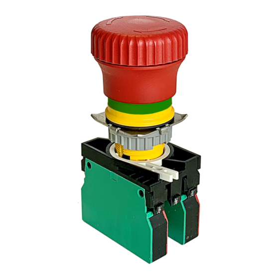
Description The red emergency stop mushroom pushbutton has a yellow ring. Directly under the mushroom pushbutton, there is also a green ring, which identifies the position status of the emergency stop button. State Ring (green) Visible Not visible Emergency stop button Not pressed Pressed Emergency stop button... - Page 14 Description Press the red emergency stop button in emergencies when • people are at risk • there is the risk of machines or the workpiece being damaged As a rule, when operating the emergency stop button, all drives are brought to a standstill with maximum braking torque.
-
Page 15: Assembly Of The Emergency Stop Button
Assembly of the emergency stop button Design ① Contact block ② Coupling ③ Threaded ring ④ Metal claw ⑤ Emergency stop button Figure 3-1 Design of the emergency stop button Dimension drawing Figure 3-2 Dimension drawing of the emergency stop button (all dimensions in mm) Emergency stop button Equipment Manual, 10/2020, A5E49939755B AA... - Page 16 Assembly of the emergency stop button Assembling the emergency stop button A description of how to connect the emergency stop button with the front plate is given below. 1. Insert the emergency stop button into the front plate. 2. Align the groove in the emergency stop button with the front plate. Depending on how you align the groove, the switching element is then mounted horizontally or vertically.
- Page 17 Assembly of the emergency stop button 4. Screw the threaded ring onto the thread. Make sure that the threaded ring grooves (see figure) point toward the contact block. The threaded ring can be mounted using an assembly tool, e.g. a socket wrench with a key width of 26 mm (double-hexagon).
- Page 18 Assembly of the emergency stop button Alternatively, you can also connect the coupling rotated 180° with the pushbutton unit. Emergency stop button Equipment Manual, 10/2020, A5E49939755B AA...
- Page 19 Assembly of the emergency stop button Disassembling the emergency stop 1. To remove the pushbutton unit from the coupling, push the white lever outwards (see figure) and pull the pushbutton unit out of the coupling. 2. Then proceed in the reverse order of assembly. Emergency stop button Equipment Manual, 10/2020, A5E49939755B AA...
- Page 20 Assembly of the emergency stop button Emergency stop button Equipment Manual, 10/2020, A5E49939755B AA...
-
Page 21: Mounting Of The Contact Blocks
Mounting of the contact blocks Mounting 1. Fasten the actuating element in the front plate with the threaded ring and the metal claw. 2. Insert the contact block into the coupling as shown and snap it into place. 3. Connect the cables. Disassembly 1. - Page 22 Mounting of the contact blocks Emergency stop button Equipment Manual, 10/2020, A5E49939755B AA...
-
Page 23: Technical Specifications
Technical specifications Rated voltage 24 V DC Rated operational current I DC-13 Q300 24 V DC / 2.75 A acc. to IEC 60947 Rated insulation voltage AC / DC 400 V DC acc. to IEC 60947 Switching capacity DC 13 acc. to EN 60947-5-1 (pushbutton unit) 130,000 (contact block, 24 V DC / 1 A) - Page 24 Technical specifications Emergency stop button Equipment Manual, 10/2020, A5E49939755B AA...
-
Page 25: Recycling And Disposal
Recycling and disposal For environmentally friendly recycling and disposal of your old device, please contact a company certified for the disposal of electrical and electronic waste and dispose of the device in accordance with the regulations in your country. Emergency stop button Equipment Manual, 10/2020, A5E49939755B AA... - Page 26 Recycling and disposal Emergency stop button Equipment Manual, 10/2020, A5E49939755B AA...
-
Page 27: Standards And Approvals
Standards and approvals China RoHS The products comply with the China RoHS directive. Further information can be found in the Internet at the following link: SIOS (https://support.industry.siemens.com/cs/document/ 109775661/china-rohs-hersteller?dti=0&lc=de-WW) Emergency stop button Equipment Manual, 10/2020, A5E49939755B AA... - Page 28 Standards and approvals Emergency stop button Equipment Manual, 10/2020, A5E49939755B AA...
Need help?
Do you have a question about the SINUMERIK ONE and is the answer not in the manual?
Questions and answers
when emergency stop button is pressed does the feed wheel stop completely
Yes, when the emergency stop button is pressed on the Siemens SINUMERIK ONE, all drives are brought to a standstill with maximum braking torque. This means the feed wheel also stops completely.
This answer is automatically generated