Siemens SINUMERIK ONE Equipment Manual
Hide thumbs
Also See for SINUMERIK ONE:
- Commissioning manual (736 pages) ,
- Operating and programming manual (312 pages) ,
- User manual (300 pages)
Table of Contents
Advertisement
Quick Links
SINUMERIK
SINUMERIK ONE
ONE MCP Part 2: MCP 2400.9c
Equipment Manual
Valid for:
Control system
SINUMERIK ONE
SINUMERIK 840D sl/840DE sl
09/2022
A5E52294261B AA
Fundamental safety
instructions
Overview
Dimension drawings
Operator control and
display elements
Technical data
Using the slide-in labels
1
2
3
4
5
6
Advertisement
Table of Contents

Related Manuals for Siemens SINUMERIK ONE


Summary of Contents for Siemens SINUMERIK ONE
- Page 1 Fundamental safety instructions Overview Dimension drawings SINUMERIK Operator control and display elements SINUMERIK ONE ONE MCP Part 2: MCP 2400.9c Technical data Using the slide-in labels Equipment Manual Valid for: Control system SINUMERIK ONE SINUMERIK 840D sl/840DE sl 09/2022 A5E52294261B AA...
- Page 2 Note the following: WARNING Siemens products may only be used for the applications described in the catalog and in the relevant technical documentation. If products and components from other manufacturers are used, these must be recommended or approved by Siemens. Proper transport, storage, installation, assembly, commissioning, operation and maintenance are required to ensure that the products operate safely and without any problems.
-
Page 3: Table Of Contents
Table of contents Fundamental safety instructions......................5 General safety instructions....................5 Equipment damage due to electric fields or electrostatic discharge ........9 Warranty and liability for application examples ..............9 Security information ......................9 Residual risks of power drive systems ................. 11 Overview.............................. - Page 4 Table of contents ONE MCP Part 2: MCP 2400.9c Equipment Manual, 09/2022, A5E52294261B AA...
-
Page 5: Fundamental Safety Instructions
Fundamental safety instructions General safety instructions WARNING Electric shock and danger to life due to other energy sources Touching live components can result in death or severe injury. • Only work on electrical devices when you are qualified for this job. •... - Page 6 Fundamental safety instructions 1.1 General safety instructions WARNING Electric shock due to equipment damage Improper handling may cause damage to equipment. For damaged devices, hazardous voltages can be present at the enclosure or at exposed components; if touched, this can result in death or severe injury.
- Page 7 • Therefore, if you move closer than 20 cm to the components, be sure to switch off radio devices, cellphones or WLAN devices. • Use the "SIEMENS Industry Online Support app" only on equipment that has already been switched off.
- Page 8 Fundamental safety instructions 1.1 General safety instructions NOTICE Overheating due to inadmissible mounting position The device may overheat and therefore be damaged if mounted in an inadmissible position. • Only operate the device in admissible mounting positions. WARNING Unexpected movement of machines caused by inactive safety functions Inactive or non-adapted safety functions can trigger unexpected machine movements that may result in serious injury or death.
-
Page 9: Equipment Damage Due To Electric Fields Or Electrostatic Discharge
Security information Siemens provides products and solutions with industrial security functions that support the secure operation of plants, systems, machines and networks. In order to protect plants, systems, machines and networks against cyber threats, it is necessary to implement –... - Page 10 Siemens’ products and solutions undergo continuous development to make them more secure. Siemens strongly recommends that product updates are applied as soon as they are available and that the latest product versions are used. Use of product versions that are no longer supported, and failure to apply the latest updates may increase customer’s exposure to cyber...
-
Page 11: Residual Risks Of Power Drive Systems
Fundamental safety instructions 1.5 Residual risks of power drive systems Residual risks of power drive systems When assessing the machine- or system-related risk in accordance with the respective local regulations (e.g., EC Machinery Directive), the machine manufacturer or system installer must take into account the following residual risks emanating from the control and drive components of a drive system: 1. - Page 12 Fundamental safety instructions 1.5 Residual risks of power drive systems ONE MCP Part 2: MCP 2400.9c Equipment Manual, 09/2022, A5E52294261B AA...
-
Page 13: Overview
Overview This manual describes the specific properties of the SINUMERIK ONE MCP 2400.9c machine control panel. The documentation is always structured in 2 parts. Part 1 contains general information that applies to all machine control panels. Part 2 covers specifics of individual machine control panels. - Page 14 Overview ONE MCP Part 2: MCP 2400.9c Equipment Manual, 09/2022, A5E52294261B AA...
-
Page 15: Dimension Drawings
Dimension drawings Plus wiring portion Figure 3-1 Front, rear and side views of the MCP 2400.9c (all dimensions in mm) The installation clearance for the MCPs is 75 mm including the wiring portion. ONE MCP Part 2: MCP 2400.9c Equipment Manual, 09/2022, A5E52294261B AA... -
Page 16: Figure 3-2 Panel Cutout
Dimension drawings Panel cutout The MCP 2400.9c is secured using 14 M5 nuts. The tightening torque is 1.5 Nm. In addition to the M5 nuts, use the spring elements provided. Customers are responsible for the geometry of the panel cutout, as well as fastening the MCP in the housing. To mechanically protect the outer edge of the front panel, the device must be installed so that it is recessed by at least 0.5 mm with respect to the surrounding housing. -
Page 17: Operator Control And Display Elements
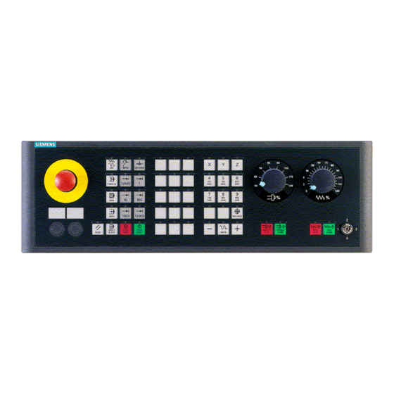
Operator control and display elements Front side Overview ① Emergency stop ② Keypad 1 (operating mode block) ③ Keypad 2 (customer key block) ④ Keypad 3 (axis block) ⑤ 1x mounting space for 22.5 mm element ⑥ 4x mounting space for 22.5 mm element ⑦... -
Page 18: Rear Side
Operator control and display elements 4.3 Configuration Rear side ① 4x mounting space for 22.5 mm element ② 1x mounting space for 22.5 mm element ③ Power supply interface X10 ④ Switch S2 ⑤ Ethernet interfaces X20 port 1/ port 2 ⑥... - Page 19 Operator control and display elements 4.3 Configuration Slot 5 Powerride 1 (feed) Slot 6 Powerride 2 (spindle) Slot 7 Handwheel 1 Slot 8 Handwheel 2 Output image Slot 1 Base Slot 2 Keypad 1 (operating mode block) Slot 3 Keypad 2 (customer key block) Slot 4 Keypad 3 (axis block), keypad 3.1 and keypad 3.2 Slot 5...
- Page 20 Operator control and display elements 4.3 Configuration ONE MCP Part 2: MCP 2400.9c Equipment Manual, 09/2022, A5E52294261B AA...
-
Page 21: Technical Data
Technical data MCP 2400.9c Safety Safety class according to EN 50178 III; PELV Degree of protection according to EN Front: IP54 Rear: IP00 60529 Approvals CE / EAC / UL Flame resistance UL 94 V-1 UL identifier MCPS2105-585210B-0492151AA0 Electrical data Overvoltage category Secondary circuit supplied from primary circuits up to Cat. - Page 22 Technical data MCP 2400.9c Relative humidity 5 ... 90% (without condensation) Permissible change in the relative humid‐ Max. 6%/h Pollution degree 2 (only use indoors) Mechanical environmental conditions Classification of the mechanical environ‐ Class 3M2 according to EN 60721-3-3 ment Vibration load during operation Frequency range: 10 –...
- Page 23 Technical data Emergency stop button Rated voltage 24 V DC Current rating, max. Current rating, min. 1 mA Switching capacity DC 13 according to EN 60947-5-1 Conditional rated short-circuit current 400 A gL/gG according to EN 60947-5-1 202500 Note The quantitative assessment of the emergency stop safety function must be based on the B values corresponding to the used standards (e.g.
- Page 24 Technical data ONE MCP Part 2: MCP 2400.9c Equipment Manual, 09/2022, A5E52294261B AA...
-
Page 25: Using The Slide-In Labels
Using the slide-in labels Use the following dimension drawing to create the slide-in labels, as well as for positioning the symbols and the cut edges of the slide-in label: ① Max. inscription area for font/ symbols Figure 6-1 Slide-in labels ONE MCP Part 2: MCP 2400.9c Equipment Manual, 09/2022, A5E52294261B AA... - Page 26 Using the slide-in labels ONE MCP Part 2: MCP 2400.9c Equipment Manual, 09/2022, A5E52294261B AA...
Need help?
Do you have a question about the SINUMERIK ONE and is the answer not in the manual?
Questions and answers