
Summary of Contents for semaphore KINGFISHER PLUS+
- Page 1 Kingfisher Plus+ Hardware Manual KINGFISHER PLUS+ Modular RTU Hardware Reference Manual 7.16...
- Page 2 Kingfisher Plus+ Hardware Manual Document Control Copyright 2000 - 2015 Copyright Semaphore Australia Pty Ltd. ABN 35 006 805 910 www.servelec-semaphore.com, info.kingfisher@servelec-semaphore.com...
- Page 3 Kingfisher Plus+ Hardware Manual Revision History Version Date Summary Number Update: adaptor ADP-22B (include Wavecom extend) Update: temp sensor is white / white with a black strip Update: power requirements of T option board Update: power calculation tables Update: Comms option boards selection table 28/10/2011 Update: safety warnings 7.12...
- Page 4 Kingfisher Plus+ Hardware Manual PS-x2 specifications adjusted IO-5 temperature rating increased to -40...+85 °C DO-1, DO-2 and TEL-REL_00x installation instructions updated IO-2, IO-3 and IO-4 specifications updated (for Digital Outputs) Dual Isolated Serial Option Board introduced Information about environmental standards compliance added Power consumption for Line and HART Option Boards updated with more accurate figures (#557) IO-4 wiring diagram corrected (#2496)
-
Page 5: Table Of Contents
Kingfisher Plus+ Hardware Manual CONTENTS 1. INTRODUCTION ..................10 2. BACKPLANES ..................16 Overview ........................16 BA-x-PLUS Backplanes ....................18 2.2.1 BA-4-PLUS: 4-slot Backplane for PC-1 Processor ..........18 2.2.2 BA-40-PLUS: 4-slot Backplane ................19 2.2.3 BA-6-PLUS: 6-slot Backplane ................20 2.2.4 BA-12-PLUS: 12-slot Backplane ................ - Page 6 Kingfisher Plus+ Hardware Manual CP-12 Processor Module ................... 68 4.3.1 Overview ......................68 4.3.2 CP-12 Reset Procedures ..................68 4.3.3 CP-12 Module LEDs ..................... 69 4.3.4 CP-12 Specifications .................... 70 4.3.5 CP-12 Ports ......................71 CP-30: High Performance Processor Module ............. 72 4.4.1 Overview ......................
- Page 7 Kingfisher Plus+ Hardware Manual 6.8.1 Line Board Connections..................107 6.8.2 Connecting a Radio .................... 108 6.8.3 2-Wire Line, point-to-point ................... 109 6.8.4 2-Wire Line, multi-drop..................109 6.8.5 4-Wire Line, point-to-point ................... 110 6.8.6 4-Wire Line, multi-drop..................110 Option Board H: HART Interface ................113 6.9.1 HART Board Connections ...................
- Page 8 Kingfisher Plus+ Hardware Manual DI-10: AC or DC Input, 16 Channel ................ 155 11.3.1 Overview......................155 11.3.2 DI-10 Options and Ordering Info ............... 156 11.3.3 Theory of operation ................... 157 11.3.4 Configurable Functions ..................158 11.3.5 Sequence of Events Recording ................. 159 11.3.6 GPS Time Synchronisation (Optional) ..............
- Page 9 Kingfisher Plus+ Hardware Manual 14.1.2 IO-2 Module LEDs .................... 199 14.1.3 IO-2 Specifications .................... 199 14.1.4 IO-2 Wiring Diagram ..................200 IO-3: Combinational Analogue/Digital IO Module ............ 202 14.2.1 Overview......................202 14.2.2 IO-3 Module LEDs .................... 204 14.2.3 IO-3 Specifications .................... 205 14.2.4 IO-3 Wiring Diagram ..................
-
Page 10: Introduction
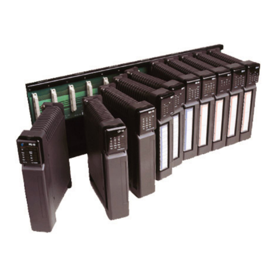
(e.g. RS232/422/485, PSTN, Ethernet, private line etc), front panel LED status and diagnostic display. Kingfisher Plus+ RTUs may be configured to user I/O, communication circuit requirements, power supply requirement and processing functionality by selecting the appropriate modules Hardware Manual Version 7.16 http://www.servelec-semaphore.com/ Page 10... - Page 11 Modular RTUs support up to 64 modules and 1008 I/O (input/output) points. To obtain more communications ports, one or more communications modules can be added to the RTU. Examples of various RTU configurations are shown below. Hardware Manual Version 7.16 http://www.servelec-semaphore.com/ Page 11...
- Page 12 Kingfisher Plus+ Hardware Manual BP-2-PLUS – based RTU BA-40-PLUS – based RTU BA-6-PLUS – based RTU Small RTUs examples Medium RTU example Hardware Manual Version 7.16 http://www.servelec-semaphore.com/ Page 12...
- Page 13 Kingfisher Plus+ Hardware Manual Large RTU example (only one processor module is required for the entire RTU) Hardware Manual Version 7.16 http://www.servelec-semaphore.com/ Page 13...
- Page 14 166 MHz 32-bit CPU, Fixed Ethernet Port + 2x Optional Ports COMMUNICATIONS MODULES Communications Module MC-12 up to 3 communications ports (incl. fixed serial port) Communications Module MC-31 up to 3 communications ports (incl. fixed Ethernet port) Hardware Manual Version 7.16 http://www.servelec-semaphore.com/ Page 14...
- Page 15 16 SPDT relay outputs, 1 common per channel SPST Relay Expansion Board TEL REL 003 16 SPST relay outputs, 1 common per channel DPDT Relay Expansion Board TEL REL 004 16 DPDT relay outputs, 2 commons per channel Hardware Manual Version 7.16 http://www.servelec-semaphore.com/ Page 15...
-
Page 16: Backplanes
All Kingfisher Plus+ backplanes are designed to be surface mounted. Mounting brackets (2 pieces) are supplied for user fitting. The backplanes can also be mounted in a 19" rack (see “Accessories” chapter for details). Hardware Manual Version 7.16 http://www.servelec-semaphore.com/ Page 16... - Page 17 Kingfisher Plus+ Hardware Manual Module Dimensions Module mounted on a backplane Installing Modules onto a Backplane Hardware Manual Version 7.16 http://www.servelec-semaphore.com/ Page 17...
-
Page 18: Ba-X-Plus Backplanes
4-slot backplane for use with a CP-xx processor and a PS-xx power supply. BA-4-PLUS backplane For information on the BA-4-PLUS backplane connectors please refer to the “Backplane Connectors” section below. Hardware Manual Version 7.16 http://www.servelec-semaphore.com/ Page 18... -
Page 19: Ba-40-Plus: 4-Slot Backplane
This backplane is designed to be used with a PS-xx power supply and a CP-xx processor module or linked to any other backplane to provide additional slots. BA-40-PLUS backplane For information on the BA-40-PLUS backplane connectors please refer to the “Backplane Connectors” section below. Hardware Manual Version 7.16 http://www.servelec-semaphore.com/ Page 19... -
Page 20: Ba-6-Plus: 6-Slot Backplane
PS-xx power supply and a CP-xx processor module or linked to any other backplane to provide additional slots. BA-6-PLUS backplane For information on the BA-6-PLUS backplane connectors please refer to the “Backplane Connectors” section below. http://www.servelec-semaphore.com/ Hardware Manual Version 7.16 Page 20... -
Page 21: Ba-12-Plus: 12-Slot Backplane
CP-xx processor module or linked to any other backplane to provide additional slots. BA-12-PLUS backplane For information on the BA-12-PLUS backplane connectors please refer to the “Backplane Connectors” section below. http://www.servelec-semaphore.com/ Hardware Manual Version 7.16 Page 21... -
Page 22: Bp-X-Plus Backplanes
If a backup power source is required then a 12 V lead-acid battery can be connected in parallel with an input power supply with its output adjusted to 13.8 V level. The BP-x-PLUS backplanes do not provide any battery charging means by themselves. BP-2-PLUS backplane Hardware Manual Version 7.16 http://www.servelec-semaphore.com/ Page 22... - Page 23 Kingfisher Plus+ Hardware Manual BP-4-PLUS backplane BP-6-PLUS backplane For information on the BP-x-PLUS backplanes connectors please refer to the “Backplane Connectors” section below. Hardware Manual Version 7.16 http://www.servelec-semaphore.com/ Page 23...
- Page 24 ), and from overcurrent (a polyfuse rated at 6 A @ 25 °C). • 5 V output is protected from overload (5 A maximum output current). • 12 V AUX output is protected from overload (2 A maximum output current). Hardware Manual Version 7.16 http://www.servelec-semaphore.com/ Page 24...
- Page 25 1. Therefore, only one BP-x-PLUS backplane can be used in the RTU. However, Power and/or Data Connectors to extend the RTU using BA-x-PLUS backplanes are available. Block-diagram of the BP-x-PLUS backplanes is shown in the figure below. BP-x-PLUS backplane Block Diagram Hardware Manual Version 7.16 http://www.servelec-semaphore.com/ Page 25...
- Page 26 Power Supply units (PS-xx). Although accidental installation of PS-xx module into a powered backplane will not cause any damage, this is not recommended as the BP-x-PLUS modules are intended to supply power independently and not designed to share power with other power sources. Hardware Manual Version 7.16 http://www.servelec-semaphore.com/ Page 26...
-
Page 27: Backplane Connectors
1. Oupiin P/Ns: 9001-3532 / 9001-3520 / 9001-3732 / 9001-3720. 2. Harting P/Ns: 09 22 132 7922 / 09 22 132 6922 / 09 22 132 2922 / 09 22 132 7921 / 09 22 132 6921 / 09 22 132 2921. Hardware Manual Version 7.16 http://www.servelec-semaphore.com/ Page 27... -
Page 28: Linking Backplanes
Connectors” section) linking them to the RTU data bus. The BP-x- PLUS backplanes have only one (OUT) connector linking them to the RTU data bus (J13). The reason for this is that the BP-x-PLUS backplane must always be the first in an RTU. Hardware Manual Version 7.16 http://www.servelec-semaphore.com/ Page 28... -
Page 29: Backplane Cables
To implement the required interconnections the cables will be required that can be either assembled (based on the data on the backplane connectors provided above) or ordered from Semaphore. The following cables are available for order: To be used with Backplanes... -
Page 30: Setting Bus Terminators
The following table outlines the DIP switch configuration required for the most recent hardware revisions of the BA-backplanes (v2.x and v3.x). For previous hardware versions please refer to the Superseded Products manual available on Semaphore Helpdesk. Hardware Manual Version 7.16 http://www.servelec-semaphore.com/... - Page 31 T o t al Nu m b e r o f R ac ks i n RT U Switch 1 Rack 2 Racks 3 Racks 4 Racks Settings 1st Rack 2nd Rack 3rd Rack 4th Rack Hardware Manual Version 7.16 http://www.servelec-semaphore.com/ Page 31...
- Page 32 Note that supplementary to the data bus connections shown, each backplane requires either a Power Supply Module installed or a power cable connected to J14. For previous backplane hardware revisions please refer to the Superseded Products Manual. Hardware Manual Version 7.16 http://www.servelec-semaphore.com/ Page 32...
-
Page 33: Setting Slot Number Range
#10 switches turned OFF should not be used as the slot numbering setting becomes undefined. An example of the possible RTU configuration, explaining rack and slot numbering sequence, is shown on the picture below. Hardware Manual Version 7.16 http://www.servelec-semaphore.com/ Page 33... - Page 34 Kingfisher Plus+ Hardware Manual Hardware Manual Version 7.16 http://www.servelec-semaphore.com/ Page 34...
-
Page 35: Power Supply Modules
Note: PS-x1 is a SUPERSEDED product and is not being manufactured currently. Fire Risks A supply voltage outside the specified limits may cause fire. Risques d'Incendie Une tension d’alimentation en dehors des limites spécifiées peut provoquer un incendie. Hardware Manual Version 7.16 http://www.servelec-semaphore.com/ Page 35... - Page 36 Ne pas le faire peut provoquer un incendie et peut entrainer des blessures graves du personnel ou même la mort. Warning The Earth Terminal in the mains power inlet provides only FUNCTIONAL EARTH connection. It cannot be relied upon for safety purposes. Hardware Manual Version 7.16 http://www.servelec-semaphore.com/ Page 36...
- Page 37 Backplane ON again regularly. RTU power will be restored permanently when overload condition is removed. Several Power Supply modules of any type can be installed on a backplane thus providing redundant and alternative power source configurations. Hardware Manual Version 7.16 http://www.servelec-semaphore.com/ Page 37...
-
Page 38: Options And Ordering Info
Notes: ) And earlier versions (here and further in this Manual). ) And later versions (here and further in this Manual). ) Linearly derated to 4.0 A from +60 °C to +85 °C. Hardware Manual Version 7.16 http://www.servelec-semaphore.com/ Page 38... -
Page 39: Theory Of Operation
(2-16 A depending on the ambient temperature, see the RUE(F)400 fuse specifications for further details), it may trip also, limiting the clamp current to several milliamperes. To recover protective circuit after tripping, the input voltage should Hardware Manual Version 7.16 http://www.servelec-semaphore.com/ Page 39... -
Page 40: Battery Charging
Battery Current. As a result, all battery status related LEDs may exhibit several various patterns depending on kind of load / source connected to the ‘B’ terminals. Hardware Manual Version 7.16 http://www.servelec-semaphore.com/ Page 40... -
Page 41: Module Leds
Boost charge is not possible (either external temperature sensor not 2.0 s OFF connected or it is faulty or battery temperature is out of -20 °C to +60 °C). Battery is not in Boost Charge mode. Hardware Manual Version 7.16 http://www.servelec-semaphore.com/ Page 41... - Page 42 ) May keep switching ON and OFF intermittently at very heavy loads (hardware hick-up mode). ) Short flashes every 2 s may indicate that PS-x2 is trying to detect battery. ) Current value given to the Processor Module is negative. ) Approximate values. Hardware Manual Version 7.16 http://www.servelec-semaphore.com/ Page 42...
- Page 43 ) Redundant Power Supply will have all LEDs turned ON when the Power Supply module is switched OFF. ) If the input supply source is disconnected from the redundant Power Supply, the Vsup LED will go OFF. Hardware Manual Version 7.16 http://www.servelec-semaphore.com/ Page 43...
-
Page 44: Ps-X2 Specifications
Electronic (v1.5) 24 V Isolated aux 24 V ± 5% 0.25 A Polyfuse Field Connector WECO 120-M-111/07 Terminal Block Plug (5.0 mm) Phoenix MSTB 2.5/7-G WECO 120-A-111/07 PCB Header (5.0 mm) Phoenix MSTB 2.5/7-ST Hardware Manual Version 7.16 http://www.servelec-semaphore.com/ Page 44... - Page 45 ) Linearly de-rated to 4.0 A from +60 °C to +85 °C (de-rating factor is 40 mA / °C above +60 °C). ) Negative: current flows from the battery (battery supplies power) Positive: current flows to the battery (battery is charged). Hardware Manual Version 7.16 http://www.servelec-semaphore.com/ Page 45...
-
Page 46: Ps-X1 Specifications
PS-21 : No 24 V Auxiliary Isolated 24 V ± 5% 0.25 A Polyfuse Field Connector WECO 120-M-111/07 Terminal Block Plug (5.0 mm) Phoenix MSTB 2.5/7-G WECO 120-A-111/07 PCB Header (5.0 mm) Phoenix MSTB 2.5/7-ST Hardware Manual Version 7.16 http://www.servelec-semaphore.com/ Page 46... - Page 47 The battery input of the PS-21 module does not have auto-resetting protection against reverse-polarity. Please ensure the battery is connected correctly. ) Negative: current flows from the battery (battery supplies power) Positive: current flows to the battery (battery is charged). Hardware Manual Version 7.16 http://www.servelec-semaphore.com/ Page 47...
-
Page 48: Wiring Diagrams
Connectez le module PS-x2/PS-x1 à l’alimentation secteur en respectant toutes les règles applicables des réglementations et normes électriques locales. L’alimentation secteur connexions du module PS-x2/PS-x1 doit se conformer à toutes les exigences d'installation répertoriées dans ce manuel. Hardware Manual Version 7.16 http://www.servelec-semaphore.com/ Page 48... - Page 49 Kingfisher Plus+ Hardware Manual Power Supply with battery backup PS-x2/PS-11 Wiring Diagram PS-21 Wiring Diagram Hardware Manual Version 7.16 http://www.servelec-semaphore.com/ Page 49...
- Page 50 Positive Terminal (+) Negative Terminal (-) connected to TS connected to B- or R- Black striped White Black Grey Black White Black Black Black Black striped Grey Hardware Manual Version 7.16 http://www.servelec-semaphore.com/ Page 50...
- Page 51 Powered from 12 – 16 V Supply: PS-x2/PS-x1 Wiring Diagram Notes: 1. A battery, a solar system or any other low voltage DC supply can be connected to the ‘B’ terminals to power the PS-x2/PS-x1 module. Hardware Manual Version 7.16 http://www.servelec-semaphore.com/ Page 51...
-
Page 52: Psu-X Ac Power Supply Unit
It cannot be relied upon for safety purposes. Avertissement de Sécurité Le terminal de terre à l’entrée de l’alimentation secteur est uniquement une connexion de TERRE FONCTIONNELLE. On ne peut pas compter sur lui pour assurer la sécurité. Hardware Manual Version 7.16 http://www.servelec-semaphore.com/ Page 52... - Page 53 Débranchez le cordon d’alimentation du module d’alimentation avant le câblage, le retrait ou l’entretien. Ne pas le faire peut provoquer un incendie et peut entrainer des blessures graves du personnel ou même la mort. Hardware Manual Version 7.16 http://www.servelec-semaphore.com/ Page 53...
- Page 54 (at 10 – 95 % RH) Operating Humidity 20 to 90 % RH (non-condensing) Weight 440 g 510 g 410 g (without mounting bracket) ) Refer to the “PSU-x Output Derating Curve” graph below. PSU-x Output Derating Curve Hardware Manual Version 7.16 http://www.servelec-semaphore.com/ Page 54...
- Page 55 Kingfisher Plus+ Hardware Manual PSU-x Block Diagram The block diagram of the PSU-x modules is shown below. PSU-x Block Diagram PSU-x Mounting PSU-x Mounting and Connections Hardware Manual Version 7.16 http://www.servelec-semaphore.com/ Page 55...
-
Page 56: Calculating Power Requirements
24 V Aux Converter Option S Board Option R Board Option P Board Bare Module Installed Installed Installed Installed For Communications Option Boards please refer to the 5 V Rail Overload Check chapter. Hardware Manual Version 7.16 http://www.servelec-semaphore.com/ Page 56... - Page 57 Extra current Extra current Extra current Extra current Absolute Part Converter Converter per Analogue per Analogue per Digital per Digital maximum number Input ON Output ON Input ON Output ON current draw AO-2 Hardware Manual Version 7.16 http://www.servelec-semaphore.com/ Page 57...
-
Page 58: Rail Overload Check
Please ensure that this limit is not exceeded by totalling the 5 V current requirements for your RTU. CP-xx and MC-xx typical 5 V Rail current consumption (mA from 5 V CP-11 CP-12 CP-30 MC-11 CP-21 MC-12 MC-31 MC-30 Hardware Manual Version 7.16 http://www.servelec-semaphore.com/ Page 58... - Page 59 10/100 Base-T Ethernet ENET-T 100 Base-FX (Fibre Optic) Ethernet ENET-A 10/100 Base-T Ethernet ENET-T2 10/100 Base-T Ethernet ENET-E 0 idle / 850 max Serial (RS-232) SER-S Line (original version) L(1) Image Capture 1000 Hardware Manual Version 7.16 http://www.servelec-semaphore.com/ Page 59...
-
Page 60: Total Power Load
The size of the backup battery required depends on how long the RTU needs to be able to run without mains power. In addition to the Total Current Load above, a backup battery will also need to power the PS-12/22 if present (not applicable if using a PC-1 processor). Hardware Manual Version 7.16 http://www.servelec-semaphore.com/ Page 60... -
Page 61: Processor Modules
Ce produit contient une pile au lithium. Il y a un risque d’explosion si la pile est remplacée par un modèle incorrect. Jetez les piles usagées conformément aux réglementations locales ou retournez- la au fournisseur. Hardware Manual Version 7.16 http://www.servelec-semaphore.com/ Page 61... -
Page 62: Pc-1: Power & Processor Module
PC-1 to CP-12 or CP-30 processors that allows existing installations to remain physically untouched. The firmware, along with technical note explaining how the modified PC-1-PS will behave, can be downloaded from a Knowledgebase article. Hardware Manual Version 7.16 http://www.servelec-semaphore.com/ Page 62... -
Page 63: Part Numbers
150K resistor). The default Radio Option card is used with Trio and Tait radios. Please indicate which Radio you are using when ordering a radio option card. Example: PC-1-CR1 is a PC-1 with 24 V auxiliary converter, radio option port and extra RAM. Hardware Manual Version 7.16 http://www.servelec-semaphore.com/ Page 63... -
Page 64: Module Leds
Processor Watchdog Timer. Set ON when the processor is reset. * The battery charging (BATT CHG) and battery discharging (DIS) LEDs will sometimes flicker on and off when the battery is charged to the optimum level or if no battery is connected. Hardware Manual Version 7.16 http://www.servelec-semaphore.com/ Page 64... -
Page 65: Specifications
120 mA from +5 V Internal Power Consumption 250 kbps I/O Bus Data Rate 83 kbps CM Bus Data Rate Port 1 and 2 Cyclic Redundanc y -20 to +70 °C Operating Temperature Hardware Manual Version 7.16 http://www.servelec-semaphore.com/ Page 65... - Page 66 * Note: backplane rail voltages are dependent on power supply to the PC-1. Most PC-1s are powered using the 40 W PSU-3 Power Supply set to 13.8 V when using a 12 V backup battery. the +24 V converter is optional and must be ordered with the PC-1. Hardware Manual Version 7.16 http://www.servelec-semaphore.com/ Page 66...
-
Page 67: Pinout
Kingfisher Plus+ Hardware Manual 4.2.5 PC-1 Pinout Port 1 Pins Direction RS-232 signal +12 V low power GND (0 V) Please refer to the PC-1 Option boards for more information regarding port 2 option boards. Hardware Manual Version 7.16 http://www.servelec-semaphore.com/ Page 67... -
Page 68: Processor Module
SRAM link on the back of the CP-12 module. Monitor Mode is a deterministic and efficient way of clearing a Processor as the module does not need to be removed from the Backplane, and as the SRAM is forcibly overwritten. Hardware Manual Version 7.16 http://www.servelec-semaphore.com/ Page 68... -
Page 69: Module Leds
IOTX IORX (this bus is used to poll all IO modules) Intensity is proportional to load on load on backplane Communications Bus CMTX CMRX (this bus is used for communications modules data transmission) Hardware Manual Version 7.16 http://www.servelec-semaphore.com/ Page 69... -
Page 70: Specifications
6 seconds. New data received during the changeover may be lost. To preserve data and for more information please see the Redundancy appendix in the Toolbox 32 manual. Hardware Manual Version 7.16 http://www.servelec-semaphore.com/ Page 70... -
Page 71: Ports
The CP-12 has a fixed serial port (RS-232) on port 1. Ports 2 and 3 can house option boards. For more information regarding communications capabilities please refer to the Communications Option Boards Chapter. Port 1 Pins Direction RS232 signal GND (0 V) Hardware Manual Version 7.16 http://www.servelec-semaphore.com/ Page 71... -
Page 72: Cp-30: High Performance Processor Module
-40 °C to +85 °C. CP-30 options, ordering info and main specification differences are summarised in the table below: Hardware Manual Version 7.16 http://www.servelec-semaphore.com/ Page 72... -
Page 73: Backup Battery / Reset To Factory Defaults
SRAM when power is removed from the module. Backup battery on v1.x is soldered to the PCB assembly of the CP-30 module. A battery retainer is used on v2.x, allowing the user to replace the battery without any special tools. Hardware Manual Version 7.16 http://www.servelec-semaphore.com/ Page 73... - Page 74 3. Keeping the pins shorted, turn on the RTU power. 4. The short can be removed any time after that. WARNING. Follow Anti-Static Procedures to avoid permanent damage to the circuit board components. Hardware Manual Version 7.16 http://www.servelec-semaphore.com/ Page 74...
- Page 75 Kingfisher Plus+ Hardware Manual CP-30 v2.x modules allow for a backup battery to be replaced by the user: 1. Obtain (purchase or order from Semaphore) a new battery. WARNING. Only CR2450N batteries from Renata are specified for operating temperature range from -40°C to +85°C.
-
Page 76: Module Leds
• Initial synchronisation with standby processor in progress. • Module fault (ISaGRAF™ not started). • Logic cycle is longer than normal (blinks momentarily, on active CP-30 only). F4 – F7 Reserved for future use. Hardware Manual Version 7.16 http://www.servelec-semaphore.com/ Page 76... - Page 77 It is usually asserted to signal readiness to transmit data to a serial device. RTS / LINK Request to Send output is not asserted. Carrier Detect input is asserted by a connected serial device. DCD / COL Carrier Detect input is not asserted. Hardware Manual Version 7.16 http://www.servelec-semaphore.com/ Page 77...
- Page 78 After a successful start-up: OK is ON; F1 and F2 are OFF; F3 is ON (for active processor) or flashing (for standby processor). ) Flash rapidly to indicate firmware upgrade error. ) CP-30 v2.x only. ) CP-30 v1.x only. Hardware Manual Version 7.16 http://www.servelec-semaphore.com/ Page 78...
-
Page 79: Specifications
-20 to +70 °C -40 to +85 °C Storage Temperature -40 to +85 °C Operating Humidity 5 to 95 % RH (non-condensing) Notes: ) No communications option cards installed on Ports 2 and 3. Hardware Manual Version 7.16 http://www.servelec-semaphore.com/ Page 79... -
Page 80: Ports
Kingfisher Plus+ Hardware Manual 4.4.6 CP-30 Ports Port 1 Pins Ethernet Signal Hardware Manual Version 7.16 http://www.servelec-semaphore.com/ Page 80... -
Page 81: Communications Modules
Ce produit contient une pile au lithium. Il y a un risque d’explosion si la pile est remplacée par un modèle incorrect. Jetez les piles usagées conformément aux réglementations locales ou retournez- la au fournisseur. Hardware Manual Version 7.16 http://www.servelec-semaphore.com/ Page 81... -
Page 82: Mc-10/11/30 Communications Modules
ON when Module is functioning correctly ON when port is transmitting ON when port is receiving Request to send. Set ON when transmitting Carrier Detect. ON while a communications signal is detected Not used L1, L2 Hardware Manual Version 7.16 http://www.servelec-semaphore.com/ Page 82... -
Page 83: Mc-10/11/30 Specifications
Yes. Module can be swapped while RTU is running. However, Hot Swap will cause a Warm Start of the Hot Swap processor. All ports will be re-initialised and ready for communications within 6 seconds. Hardware Manual Version 7.16 http://www.servelec-semaphore.com/ Page 83... -
Page 84: Mc-10/11/30 Block Diagram
Port 1 is at the top for RS232 connections only. Port 2 and 3 can be configured using plug-in option boards. Port 1 Pins Direction RS232 signal GND (0 V) Hardware Manual Version 7.16 http://www.servelec-semaphore.com/ Page 84... -
Page 85: Communications Module
This module consumes power from the +5 V bus on the backplane. It also requires +12 V . One or more MC-12 modules can be installed in any I/O slot of a 4, 6 or 12 slot backplane. Hardware Manual Version 7.16 http://www.servelec-semaphore.com/ Page 85... -
Page 86: Module Leds
Brightness of each indicates load on backplane IO Bus IOTX IORX (this bus is used to poll all IO modules) Brightness of each indicates load on backplane Communications Bus CMTX CMRX (this bus is used for communications modules data transmission) Hardware Manual Version 7.16 http://www.servelec-semaphore.com/ Page 86... -
Page 87: Specifications
(without Option Boards) 250 kbps I/O Bus Data Rate 83 kbps CM Bus Data Rate -20 to +70 °C Operating Temperature -40 to +85 °C Storage Temperature 5 to 95 % RH (non-condensing) Operating Humidity Hardware Manual Version 7.16 http://www.servelec-semaphore.com/ Page 87... -
Page 88: Ports
The MC-12 has a fixed serial port (RS-232) on port 1. Ports 2 and 3 can house option boards. For more information regarding communications capabilities please refer to the Communications Option Boards chapter. Port 1 Pins Direction RS232 signal GND (0 V) Hardware Manual Version 7.16 http://www.servelec-semaphore.com/ Page 88... -
Page 89: Communications Module
) And later versions (referred to as v2.x further in this Manual). ) ‘x’ designates a code of the communications option board installed on Port 2. ) ‘y’ designates a code of the communications option board installed on Port 3. Hardware Manual Version 7.16 http://www.servelec-semaphore.com/ Page 89... -
Page 90: Module Leds
Firmware/configuration update in progress. 0.5 s OFF Power off or module faulty. 0.25 s ON, Port 2 configuration error. 0.25 s OFF Normal operation. 0.25 s ON, Port 3 configuration error. 0.25 s OFF Normal operation. Hardware Manual Version 7.16 http://www.servelec-semaphore.com/ Page 90... - Page 91 Carrier Detect input is not asserted. P2 (Port 2) and P3 (Port 3) LEDs: Ax and Tx (Ethernet) options Flashing Data activity (transmit or receive) at 10 Mbps. TxD / 10ACT No data activity at 10 Mbps. Hardware Manual Version 7.16 http://www.servelec-semaphore.com/ Page 91...
- Page 92 ) Progressively set ON during booting sequence. After a successful start-up: OK is ON; F1, F2 and F3 are OFF. ) Flash rapidly to indicate firmware upgrade error. ) MC-31 v2.x only. ) MC-31 v1.x only. Hardware Manual Version 7.16 http://www.servelec-semaphore.com/ Page 92...
-
Page 93: Specifications
-20 to +70 °C -40 to +85 °C Storage Temperature -40 to +85 °C Operating Humidity 5 to 95 % RH (non-condensing) Notes: ) No communications option cards installed on Ports 2 and 3. Hardware Manual Version 7.16 http://www.servelec-semaphore.com/ Page 93... -
Page 94: Ports
Kingfisher Plus+ Hardware Manual 5.4.5 MC-31 Ports Port 1 Pins Ethernet Signal Hardware Manual Version 7.16 http://www.servelec-semaphore.com/ Page 94... -
Page 95: Communications Option Boards
The list of modules that can support a particular Option Board is provided in the corresponding Option Board specifications table. The following table summarises compatibility information to offer a selection guide for assuring the hardware you have selected will function as expected. Hardware Manual Version 7.16 http://www.servelec-semaphore.com/ Page 95... -
Page 96: Installing And Removing Option Boards
PC-1 with MC-12 Note: The above table was correct at the time of writing. Please refer to Semaphore Helpdesk for any recent changes. Installing and removing Option Boards Warning: Follow anti-static procedures Electronic components can be damaged by even small amounts of static discharge. - Page 97 3. Repeat steps 1 and 2 above for the top of the module. 4. Once all 4 tabs have been released, remove the front cover. 5. Remove the circuit board from the case by using a ‘toggling’ action Hardware Manual Version 7.16 http://www.servelec-semaphore.com/ Page 97...
- Page 98 8. Press the bottom of the cover onto the case. At the same time, please ensure that the option boards line up with the cutouts. Ensure the cover is fully inserted and that the 4 tabs have all engaged. Hardware Manual Version 7.16 http://www.servelec-semaphore.com/ Page 98...
-
Page 99: Option Board I: Isolated Serial
5 to 95 % RH (non-condensing) Can be installed in any of the following ports: CP-10/11/12/21/30 Port 2 or Port 3 RTU Hardware Required MC-10/11/12/30/31 Port 2 or Port 3 LP-1/2 Port4 LP-3 Port 3 or Port 4 Hardware Manual Version 7.16 http://www.servelec-semaphore.com/ Page 99... -
Page 100: Serial Option Board Connections
Kingfisher Plus+ Hardware Manual 6.4.2 Serial Option Board Connections RJ45 Pin Direction RS-232 RS-422 / RS-485 4.3 V Common RS-232 Wiring Diagram (Null Modem Cable) Note: maximum recommended RS-232 cable length is 15 meters. Hardware Manual Version 7.16 http://www.servelec-semaphore.com/ Page 100... - Page 101 If GND wire is not available, each GND terminal can be earthed locally via 100 Ω 0.5 W resistors. If the 100 Ω resistor is not available, the Ground wire can be connected directly to EARTH. Hardware Manual Version 7.16 http://www.servelec-semaphore.com/ Page 101...
-
Page 102: Option Board I2: Dual Isolated Serial
Tx (for data transmission) and Rx (for data reception) LEDs mounted on the RJ45 connector as shown on the picture above. Activity indication of the Port 1.x is also duplicated on the corresponding front panel LEDs of the hosting CP-30/MC-31 module. Hardware Manual Version 7.16 http://www.servelec-semaphore.com/ Page 102... -
Page 103: Dual Serial Option Board Connections
RJ45 Pin Direction RS-232 RS-422 / RS-485 N.C. N.C. Common Wiring diagrams for each port of the Dual Serial Option Board are the same as shown in the “Serial Option Board Connections” chapter earlier. Hardware Manual Version 7.16 http://www.servelec-semaphore.com/ Page 103... -
Page 104: Option Board F: Fibre Optic Serial Board
Operating Humidity Can be installed in any of the following ports: CP-10/11/12/21/30 Port 2 or Port 3 MC-10/11/12/30/31 Port 2 or Port 3 RTU Hardware Required LP-1/2 Port4 LP-3 Port 3 or Port 4 Hardware Manual Version 7.16 http://www.servelec-semaphore.com/ Page 104... -
Page 105: Option Board D: 33.6 Kbps Dial Option Board
To reduce risk of fire, use only 26 AWG (0.13 mm ) or larger telecommunications line cord. Ligne de Télécommunication Cordon Pour réduire les risques d’incendie, utilisez seulement du câble d’une section minimale de 0.13 mm² (26 AWG) pour les connections de télécommunications. Hardware Manual Version 7.16 http://www.servelec-semaphore.com/ Page 105... - Page 106 5 to 95 % RH (non-condensing) Operating Humidity Can be installed in any of the following ports: CP-10/11/12/21/30 Port 2 or Port 3 Compatibility MC-10/11/12/30/31 Port 2 or Port 3 LP-1/2 Port4 LP-3 Port 3 or Port 4 Hardware Manual Version 7.16 http://www.servelec-semaphore.com/ Page 106...
-
Page 107: Option Board L: Line/Analogue Radio Interface
Tx - Rx - RTS/PTT GND (0 V) 12 V Rx + Tx + Telecommunication Line Cord To reduce risk of fire, use only 26 AWG (0.13 mm ) or larger telecommunications line cord. Hardware Manual Version 7.16 http://www.servelec-semaphore.com/ Page 107... -
Page 108: Connecting A Radio
2. Modify the radio by removing the internal pull up, as per manufacturer’s instructions. 3. Use +5 V to supply the carrier detect optoisolation circuit. (DO NOT USE +5 V FROM THE BACKPLANE CONNECTOR AS IT IS NOT ISOLATED). Line / Radio Option Board Interface Hardware Manual Version 7.16 http://www.servelec-semaphore.com/ Page 108... -
Page 109: 2-Wire Line, Point-To-Point
6.8.3 2-Wire Line, point-to-point Either RTU can transmit/receive one at a time. Note: line termination is required. 6.8.4 2-Wire Line, multi-drop Any RTU can transmit/receive one at a time. Note: line termination is required. Hardware Manual Version 7.16 http://www.servelec-semaphore.com/ Page 109... -
Page 110: 4-Wire Line, Point-To-Point
6.8.6 4-Wire Line, multi-drop Master RTU can transmit/receive to any one outstation RTU at any time or each outstation can transmit/receive to master RTU, one at a time. Note that outstations cannot communicate to each other. Hardware Manual Version 7.16 http://www.servelec-semaphore.com/ Page 110... - Page 111 Maximum working voltage in respect to system earth/ground must not exceed TNV-2 limits (80 V) Isolation Transient voltage: 3.88 kV -20 to +70 °C Operating Temperature -40 to +85 °C Storage Temperature 5 to 95 % RH (non-condensing) Operating Humidity Hardware Manual Version 7.16 http://www.servelec-semaphore.com/ Page 111...
- Page 112 Kingfisher Plus+ Hardware Manual Can be installed in any of the following ports: CP-10/11/12/21/30 Port 2 or Port 3 MC-10/11/12/30/31 Port 2 or Port 3 Compatibility LP-1/2 Port4 LP-3 Port 3 or Port 4 Hardware Manual Version 7.16 http://www.servelec-semaphore.com/ Page 112...
-
Page 113: Option Board H: Hart Interface
RTU analogue input channels must be isolated from each other. In a multi-drop installation, the loop current is not used or measured. For more information regarding HART configurations please refer to the “HART Implementation Guide” available on Semaphore Helpdesk. 6.9.1 HART Board Connections RJ45 Pin... - Page 114 Note: the resistor value can be from 50 to 500 Ohm. The more HART devices connected, the closer the resistor value needs to be to 50 Ohm. When using multiple HART networks on a single RTU, be sure to isolate the 24 V supplies. Hardware Manual Version 7.16 http://www.servelec-semaphore.com/ Page 114...
- Page 115 -40 to +85 °C Storage Temperature 5 to 95 % RH (non-condensing) Operating Humidity Can be installed in any of the following ports: CP-10/11/12/30 Port 2 or Port 3 Compatibility MC-30/31 Port 2 or Port 3 Hardware Manual Version 7.16 http://www.servelec-semaphore.com/ Page 115...
-
Page 116: Option Boards T3 & T2: 10/100 Ethernet Controller
CP-30 Port 2 or Port 3 Compatibility MC-11/12/31 Port 2 or Port 3 MC-30/31 Port 2 or Port 3 LP-2 Port 4 LP-3 Port 3 or Port 4 Ethernet Port 1 Pins Function Hardware Manual Version 7.16 http://www.servelec-semaphore.com/ Page 116... -
Page 117: Option Board A3: Fibre Optic Ethernet
Multimode 50/125 um, 62.5/125 um, 100/140 um, and 200 um Supported Fiber Optic Cables MTRJ connector. Option Board Connectors Available from Semaphore are the MTRJ-SC and MTRJ-ST (use male connectors on cable) adaptors. Internal Power Consumption 600 mA from +5 V... -
Page 118: Option Board R2: Australian Spread Spectrum Radio
émetteur doivent être installées pour garantir une distance d’au moins 30 cm de toutes personnes et ne doivent pas être proche ou en opération en conjonction avec n’importe quel autre antenne ou émetteur. Hardware Manual Version 7.16 http://www.servelec-semaphore.com/ Page 118... - Page 119 CP-10/11/12/30 Port 2 or Port 3 Compatibility MC-10/11/12/30/31 Port 2 or Port 3 LP-1/2 Port4 LP-3 Port 3 or Port 4 Please see http://www.digi.com for more information on XTend® 900MHz wireless module (P/N XTH9-MI-NA) specifications. Hardware Manual Version 7.16 http://www.servelec-semaphore.com/ Page 119...
-
Page 120: Option Board R3: International Spread Spectrum Radio
émetteur. Modifications Use of unauthorised antenna or other changes or modifications not expressly approved by the party responsible for compliance could void the user’s authority to operate this product. Hardware Manual Version 7.16 http://www.servelec-semaphore.com/ Page 120... - Page 121 MC-10/11/12/30/31 Port 3 only LP-2 Port4 LP-3 Port 3 or Port 4 Encryption by special request in the USA only. Please see http://www.digi.com/ for more information on XStream® 2.4GHz wireless module (P/N X24-019NMI) specifications. Hardware Manual Version 7.16 http://www.servelec-semaphore.com/ Page 121...
-
Page 122: Option Board R4: Us/Canada Spread Spectrum Radio
émetteur. Modifications Use of unauthorised antenna or other changes or modifications not expressly approved by the party responsible for compliance could void the user’s authority to operate this product. Hardware Manual Version 7.16 http://www.servelec-semaphore.com/ Page 122... - Page 123 MC-10/11/12/30/31 Port 2 or Port 3 LP-1/2 Port4 LP-3 Port 3 or Port 4 Encryption by special request in the USA only. Please see http://www.digi.com for more information on XTend® 900MHz wireless module (P/N XT09-MI-NA) specifications. Hardware Manual Version 7.16 http://www.servelec-semaphore.com/ Page 123...
-
Page 124: Option Boards
+12 V low power LINE - * GND (0 V) GND (0 V) LINE + * * Polarity is opposite to CP-xx For RS-485 wiring diagram please refer to CP-xx/MC-xx serial board RS-485 Diagrams Hardware Manual Version 7.16 http://www.servelec-semaphore.com/ Page 124... -
Page 125: Modem Board Pl: Two Wire Line
The board is optically isolated, operates at 1200 bps and utilizes FSK CCITT V.23 modulation. PC-1 Modem Board Connections RJ45 Pin Direction Radio Function +12 V low power GND (0 V) PC-1 2 Wire Line Wiring Diagram (point-to-point) Hardware Manual Version 7.16 http://www.servelec-semaphore.com/ Page 125... -
Page 126: Modem Board: Analogue Radio Interface
The default Radio Option card is used with Trio and Tait radios. Please indicate which Radio you are using when ordering a radio option card. PC-1 Analogue Radio Board Connections RJ12 Pin Direction Radio Function +12 V low power GND (0 V) Hardware Manual Version 7.16 http://www.servelec-semaphore.com/ Page 126... -
Page 127: Io Modules Overview
This allows the IO module to be swapped without having to detach the field wiring from the I/O connector. The I/O connector is secured to the module using two fastening screws as shown on the picture below. Hardware Manual Version 7.16 http://www.servelec-semaphore.com/ Page 127... - Page 128 One wire is connected to a positive terminal of an external supply or to the Field Power output of the module. The second wire is connected to Hardware Manual Version 7.16 http://www.servelec-semaphore.com/ Page 128...
- Page 129 In extreme noise environments, a ground braid may be used to connect the frame ground on the base plate connector to earth ground. This additional connection will bypass noise around the module. An internal link is Hardware Manual Version 7.16 http://www.servelec-semaphore.com/ Page 129...
- Page 130 Kingfisher Plus+ Hardware Manual factory fitted on each module for the GND connection and may be removed where high isolation for cabling is required. Shield Connections for Analogue Outputs Hardware Manual Version 7.16 http://www.servelec-semaphore.com/ Page 130...
-
Page 131: Analogue Input Modules
(0000H in #AI). If an input that is out of range is entered (i.e. greater than 20 mA), the A/D converter will output up to full scale (corresponding to 7FF8H in #AI). Hardware Manual Version 7.16 http://www.servelec-semaphore.com/ Page 131... - Page 132 The shields can be connected to GND. The GND connection provides access to the backplane (frame ground). This module can be installed in any I/O slot of a 4, 6 or 12-slot backplane. Hardware Manual Version 7.16 http://www.servelec-semaphore.com/ Page 132...
-
Page 133: Module Leds
Block-diagram of the AI-1 module is shown on the figure below. AI-1 Block Diagram 9.1.2 AI-1 Module LEDs State Description Module fault (no power) Normal Fuse OK Fuse fail Channel Input level < 1% A1-A8 Channel Input level > 1% Hardware Manual Version 7.16 http://www.servelec-semaphore.com/ Page 133... -
Page 134: Specifications
It is recommended that modules be returned to Semaphore for factory conversion if required. No responsibility will be taken by Semaphore for damage caused to boards during modification performed by clients. The circuit board resistors to change are: R9 to R16 (channels 1 to 8 correspondingly). -
Page 135: Wiring Diagram
Kingfisher Plus+ Hardware Manual 9.1.4 AI-1 Wiring Diagram The insert in the hinged cover of the terminal strip has circuit wiring information. Circuit identification information can be recorded on the outside surface of the insert. Hardware Manual Version 7.16 http://www.servelec-semaphore.com/ Page 135... - Page 136 2 wire transmitter (powered by module) 3 wire transmitter (powered by module) 4 wire transmitter (powered by module) 2 wire transmitter (powered externally) 3 wire transmitter (powered externally) 4 wire transmitter (powered externally) Hardware Manual Version 7.16 http://www.servelec-semaphore.com/ Page 136...
-
Page 137: Ai-10: 8 Channel High Impedance Analogue Input Module
R64 to R71 (channels 1 to 8 correspondingly). It is recommended that modules be returned to Semaphore for factory conversion if required. No responsibility will be taken by Semaphore for damage caused to boards during modification performed by clients. - Page 138 This module consumes power from the +5 V and +12 V RTU rails. A built-in 24V DC-DC converter is used to provide isolated power to the analogue front-end and can also be utilised to power the field devices if required. Hardware Manual Version 7.16 http://www.servelec-semaphore.com/ Page 138...
- Page 139 Kingfisher Plus+ Hardware Manual Block-diagrams of the AI-10 modules are shown on the figures below. AI-10 v1.x Block Diagram AI-10 v2.x Block Diagram Hardware Manual Version 7.16 http://www.servelec-semaphore.com/ Page 139...
-
Page 140: Module Leds
Channel Input level > 1% Channel Normal (right side) Channel Fault (under/over range, data invalid) ) On AI-10 v2.x only Note: On power up some LEDs may come ON for a short time. Hardware Manual Version 7.16 http://www.servelec-semaphore.com/ Page 140... -
Page 141: Specifications
250 Ω channel resistor. ) The ±10 V input range can only be used on an AI-10 input channel if the current sensing resistor has been disconnected. Resistors have already been disconnected in an AI-10-V. Hardware Manual Version 7.16 http://www.servelec-semaphore.com/ Page 141... -
Page 142: Ai-10-V Wiring Diagram
9.2.4 AI-10 / AI-10-V Wiring Diagram The insert in the hinged cover of the terminal strip has circuit wiring information. Circuit identification information can be recorded on the outside surface of the insert. Hardware Manual Version 7.16 http://www.servelec-semaphore.com/ Page 142... - Page 143 +24 V Output. Note: Any channels sharing the same power source (e.g. +24 V from module or a field power supply) are no longer isolated from one other. Hardware Manual Version 7.16 http://www.servelec-semaphore.com/ Page 143...
-
Page 144: Analogue Output Module
20 mA. A range link (on the rear of the module) selects either 4-20 mA or 0-20 mA for all four channels. The default condition is 4-20 mA with the link on. The module provides 12 bits of resolution in either range. Scaling of the output is shown below. Hardware Manual Version 7.16 http://www.servelec-semaphore.com/ Page 144... - Page 145 This module can be installed in any I/O slot of a 4, 6 or 12 slot backplane in a system. Up to 10 Analogue output modules can be installed on a single 12-slot backplane. AO-3 configuration link location Hardware Manual Version 7.16 http://www.servelec-semaphore.com/ Page 145...
-
Page 146: Module Leds
Normal Module running Module in Reset (power-on or watchdog) Channel output set to 0% ANALOGUE OUT 1-4 Channel output greater than 0% Closed Loop (load detected) OPEN LOOP 1-4 Open Loop (no load) Hardware Manual Version 7.16 http://www.servelec-semaphore.com/ Page 146... -
Page 147: Specifications
Yes. Monitors output circuit for failure (e.g. cable breakage) or if the load is disconnected. Open Loop Detection Note: when using the 0-20 mA range, Open Loop Detection cannot be guaranteed on an output when set below 160 / 0.1 mA / 0.5%. Hardware Manual Version 7.16 http://www.servelec-semaphore.com/ Page 147... -
Page 148: Wiring Diagram
Kingfisher Plus+ Hardware Manual 10.1.4 AO-3 Wiring Diagram The insert in the hinged cover of the terminal strip has circuit wiring information. Circuit identification information can be recorded on the outside surface of the insert. Hardware Manual Version 7.16 http://www.servelec-semaphore.com/ Page 148... - Page 149 Kingfisher Plus+ Hardware Manual 0 – 20 / 4 – 20 mA Current Loop Receiver Hardware Manual Version 7.16 http://www.servelec-semaphore.com/ Page 149...
-
Page 150: Digital Input Modules
10 kHz on inputs 1 and 2 and can count up to 255 Hz on inputs 3 and 4. The pulse total and the frequency for each of the first 4 digital inputs are stored. This module can be installed in any I/O slot of a 4, 6 or 12 slot backplane system. Hardware Manual Version 7.16 http://www.servelec-semaphore.com/ Page 150... -
Page 151: Module Leds
Block-diagram of the DI-5 module is shown on the figure below. DI-5 Block Diagram 11.2.2 DI-5 Module LEDs State Description Module fault (no power) Normal Digital Input OFF 1 - 16 Digital Input ON Hardware Manual Version 7.16 http://www.servelec-semaphore.com/ Page 151... -
Page 152: Specifications
Channels 3 and 4 : 255 Hz maximum Yes. Module can be swapped while RTU is running. Hot swap will not Hot Swap cause a Warm Start. Inputs are cleared in RTU memory while module is removed. Hardware Manual Version 7.16 http://www.servelec-semaphore.com/ Page 152... -
Page 153: Wiring Diagram
Kingfisher Plus+ Hardware Manual 11.2.4 DI-5 Wiring Diagram The insert in the hinged cover of the terminal strip has circuit wiring information. Circuit identification information can be recorded on the outside surface of the insert. Hardware Manual Version 7.16 http://www.servelec-semaphore.com/ Page 153... - Page 154 Kingfisher Plus+ Hardware Manual Powered by Module: External positive supply: External negative supply: Combined positive and negative power supplies: Hardware Manual Version 7.16 http://www.servelec-semaphore.com/ Page 154...
-
Page 155: Di-10: Ac Or Dc Input, 16 Channel
PEAK earth and/or ground) before performing any operation on this product, including field wiring. Failure to do so may cause fire and may result in a serious personnel injury or even death. Hardware Manual Version 7.16 http://www.servelec-semaphore.com/ Page 155... -
Page 156: Options And Ordering Info
Slaves and GPS Masters can be installed in the RTU. With more than one GPS Master installed in the system, each of them will generate time synchronisation signal for the GPS Slaves in parallel, providing system redundancy if it is required. Hardware Manual Version 7.16 http://www.servelec-semaphore.com/ Page 156... -
Page 157: Theory Of Operation
) DI-10-48 refers also to DI-10-1-48 and to DI-10-48GPS models further in this document. ) DI-10-GPS refers also to DI-10-48GPS model further in this document. 11.3.3 Theory of operation Block-diagram of DI-10 v3.2 module is shown on the figure below. DI-10 v3.2 Block Diagram Hardware Manual Version 7.16 http://www.servelec-semaphore.com/ Page 157... -
Page 158: Configurable Functions
Software debounce can be activated on any input channel. The time constant can be configured from 1 ms to 250 ms. When AC inputs are used, the input channel must be configured with the debounce filter set to ‘AC Filter’ as shown below. Hardware Manual Version 7.16 http://www.servelec-semaphore.com/ Page 158... -
Page 159: Sequence Of Events Recording
Kingfisher Plus+ installations) will damage DI-10 modules and void their warranty. To support time synchronisation of the DI-10 modules across multiple backplanes, the time synchronisation signal must be connected between them. This signal is available on backplane power connector J14: Hardware Manual Version 7.16 http://www.servelec-semaphore.com/ Page 159... - Page 160 The DI-10-GPS has an RJ-45 jack for direct connection of a Garmin GPS16x-HVS device. It is located directly underneath the LED display of the DI-10-GPS module. The Garmin GPS16x-HVS can be ordered from Semaphore directly or via many commercial outlets.
-
Page 161: Module Leds
RS-232 Serial Data to GPS Dout RS-232 Serial Data from GPS 5 V TTL Pulse Per Second Not connected Not connected 11.3.7 DI-10 Module LEDs DI-10-1 [-48] (v3.2) DI-10 [-48] (v4.3) DI-10-[48]GPS (v4.3) Hardware Manual Version 7.16 http://www.servelec-semaphore.com/ Page 161... - Page 162 Digital Input ON (channel input level is above low-to-high threshold) 1-16 Digital Input OFF (channel input level is below high-to-low threshold) Notes: ) Only hardware v4.3 or later. ) Only on DI-10-GPS modules (GPS Master). Hardware Manual Version 7.16 http://www.servelec-semaphore.com/ Page 162...
-
Page 163: Specifications
6.3 V / 4.4 V 5.1 V / 3.7 V (Ch. 5-16) 36.0 V / 25.5 V (Ch. 1-4) -48 modules 25.5 V / 18.4 V 34.5 V / 24.3 V (Ch. 5-16) Hardware Manual Version 7.16 http://www.servelec-semaphore.com/ Page 163... - Page 164 10 kHz 1 kHz (Ch. 5-16) Frequency Counting 1 Hz resolution on any input(s) Pulse Counting 0-65535 Pulses on any input(s) Quadrature Counting 0-65535 Pulses on any of the inputs pair(s) 1-2, 3-4, etc. Hardware Manual Version 7.16 http://www.servelec-semaphore.com/ Page 164...
- Page 165 Backplane time synchronisation latency (that is influenced by the type of the Processor module used and by its loading with the RTU logic and communications), by the number of installed DI-10 modules and by other system-dependent parameters. ) Only on DI-10-GPS modules (GPS Master) Hardware Manual Version 7.16 http://www.servelec-semaphore.com/ Page 165...
-
Page 166: Wiring Diagram
Note 2. Pins 10 and 20 (0V) are connected together internally. Powered by Module External DC Power Supply Note: DC voltage applied to any input channel must be positive in respect to 0V. Hardware Manual Version 7.16 http://www.servelec-semaphore.com/ Page 166... - Page 167 DC and AC powered inputs can be used simultaneously on the same module. Care should be taken to ensure that the negative rail of each external power supply is connected to the Common (0V) terminal. Hardware Manual Version 7.16 http://www.servelec-semaphore.com/ Page 167...
-
Page 168: Digital Output Modules
To mitigate this negative effect, suppression circuits should be used when switching inductive loads. Switching DC Supplied inductive loads (high switching relay output) Switching DC Supplied inductive loads (ground switching relay output) Hardware Manual Version 7.16 http://www.servelec-semaphore.com/ Page 168... - Page 169 Kingfisher Plus+ Hardware Manual Switching AC supplied inductive loads (*MOV = Metal Oxide Varistor) Hardware Manual Version 7.16 http://www.servelec-semaphore.com/ Page 169...
-
Page 170: Do-1: 8 Channel Isolated Relay Output Module
à la terre du système et/ou du sol) POINTE avant d’effectuer toute opération sur ce produit, y compris le câblage. Ne pas le faire peut provoquer un incendie et peut entrainer des blessures graves ou même la mort du personnel. Hardware Manual Version 7.16 http://www.servelec-semaphore.com/ Page 170... -
Page 171: Module Leds
DO-1 Block Diagram 12.3.2 DO-1 Module LEDs State Description Module fault (no power) Normal Fuse OK Fuse fail A1, A2 Digital output OFF (open) B3, B4 C5, C6 Digital output ON (closed) D7, D8 Hardware Manual Version 7.16 http://www.servelec-semaphore.com/ Page 171... -
Page 172: Specifications
CAUTION! Contacts should be protected with appropriate suppression devices when wired with inductive loads to increase the service life of relays (please see the "Switching Inductive Loads" section for more details). Contacts should also be protected with external fusing. Hardware Manual Version 7.16 http://www.servelec-semaphore.com/ Page 172... -
Page 173: Wiring Diagram
Kingfisher Plus+ Hardware Manual 12.3.4 DO-1 Wiring Diagram The insert in the hinged cover of the terminal strip has circuit wiring information. Circuit identification information can be recorded on the outside surface of the insert. Hardware Manual Version 7.16 http://www.servelec-semaphore.com/ Page 173... - Page 174 PEAK system earth and/or ground) then all Common Terminals of the module must be connected to a single power source and no other power sources can be connected to the same module. Hardware Manual Version 7.16 http://www.servelec-semaphore.com/ Page 174...
-
Page 175: Do-2: 16 Channel Relay Output Module
Internal fuses protect the DO-2 relay contacts should ratings be exceeded. This module can be installed in any I/O slot of a 4, 6 or 12 slot backplane. Block-diagram of the DO-2 module is shown on the figure below. DO-2 Block Diagram Hardware Manual Version 7.16 http://www.servelec-semaphore.com/ Page 175... - Page 176 à la terre du système et/ou du sol) POINTE avant d’effectuer toute opération sur ce produit, y compris le câblage. Ne pas le faire peut provoquer un incendie et peut entrainer des blessures graves ou même la mort du personnel. Hardware Manual Version 7.16 http://www.servelec-semaphore.com/ Page 176...
-
Page 177: Module Leds
(DC 60 V or AC 42 V relative to system earth and/or ground) then both commons must PEAK be connected to a single power source and no other power sources are allowed to be connected to this module. Hardware Manual Version 7.16 http://www.servelec-semaphore.com/ Page 177... -
Page 178: Wiring Diagram
Contacts should also be protected with external fusing. 12.4.4 DO-2 Wiring Diagram The insert in the hinged cover of the terminal strip has circuit wiring information. Circuit identification information can be recorded on the outside surface of the insert. Hardware Manual Version 7.16 http://www.servelec-semaphore.com/ Page 178... - Page 179 PEAK system earth and/or ground) then both Common Terminals of the module must be connected to a single power source and no other power sources can be connected to the same module. Hardware Manual Version 7.16 http://www.servelec-semaphore.com/ Page 179...
-
Page 180: Do-6: 16 Channel Open Drain Output Module
This module can be installed in any I/O slot of a 4, 6 or 12 slot backplane. Block-diagram of the DO-6 module is shown on the figure below. DO-6 Block Diagram Hardware Manual Version 7.16 http://www.servelec-semaphore.com/ Page 180... -
Page 181: Module Leds
Yes. Module can be swapped while RTU is running. Hot swap will not Hot Swap cause a Warm Start. Outputs will be restored within 2 seconds once module is replaced. The DO-6 is functionally equivalent and pin compatible with the Compatibility superseded DO-5. Hardware Manual Version 7.16 http://www.servelec-semaphore.com/ Page 181... -
Page 182: Wiring Diagram
Kingfisher Plus+ Hardware Manual 12.5.4 DO-6 Wiring Diagram The insert in the hinged cover of the terminal strip has circuit wiring information. Circuit identification information can be recorded on the outside surface of the insert. Hardware Manual Version 7.16 http://www.servelec-semaphore.com/ Page 182... - Page 183 Note: The +12 V Output is sourced from the backplane power rail and is not isolated. Users should exercise caution to avoid shorting or overloading this output. External DC power supply: Load powered by module: Hardware Manual Version 7.16 http://www.servelec-semaphore.com/ Page 183...
-
Page 184: Relay Expansion Boards
PEAK earth and/or ground) before performing any operation on this product, including field wiring. Failure to do so may cause fire and may result in a serious personnel injury or even death. Hardware Manual Version 7.16 http://www.servelec-semaphore.com/ Page 184... - Page 185 à la terre du système et/ou du sol) POINTE avant d’effectuer toute opération sur ce produit, y compris le câblage. Ne pas le faire peut provoquer un incendie et peut entrainer des blessures graves ou même la mort du personnel. Hardware Manual Version 7.16 http://www.servelec-semaphore.com/ Page 185...
-
Page 186: Tel Rel 002: Spdt Relay Board
Storage Temperature -40 to +85 °C Humidity 5 to 95 % RH (non-condensing) Isolation 5 kV coil to contacts Coil Rated Voltage 12 V @ 43 mA 275 Ω @ 12 V Coil Resistance Hardware Manual Version 7.16 http://www.servelec-semaphore.com/ Page 186... - Page 187 (DC 60 V or AC 42 V relative to system earth and/or ground) then all used commons PEAK must be connected to a single power source and no other power sources are allowed to be connected to this module. Hardware Manual Version 7.16 http://www.servelec-semaphore.com/ Page 187...
-
Page 188: Tel Rel 002 Wiring Diagram
Kingfisher Plus+ Hardware Manual 13.2.3 TEL REL 002 Wiring Diagram DO-6 to TEL REL 00x Interface Cable Hardware Manual Version 7.16 http://www.servelec-semaphore.com/ Page 188... - Page 189 Orange/Black Channel 9 Blue/Black Channel 10 Black/White Channel 11 Red/White Channel 12 Green/White Channel 13 Blue/White Channel 14 Black/Red Channel 15 White/Red Channel 16 Orange/Red + 12 V Blue/Red + 12 V Green/Red Hardware Manual Version 7.16 http://www.servelec-semaphore.com/ Page 189...
-
Page 190: Tel Rel 003: Spst Relay Board
Interface Cable Length 1.5 m (for connection to the DO-6 module) Weidmuller single height PCB 3-way terminal unit (please see Connection Terminals wiring diagram). These terminals can take wire sizes up to 4 mm Hardware Manual Version 7.16 http://www.servelec-semaphore.com/ Page 190... -
Page 191: Tel Rel 003 Wiring Diagram
PEAK must be connected to a single power source and no other power sources are allowed to be connected to this module. 13.3.3 TEL REL 003 Wiring Diagram Hardware Manual Version 7.16 http://www.servelec-semaphore.com/ Page 191... - Page 192 Orange/Black Channel 9 Blue/Black Channel 10 Black/White Channel 11 Red/White Channel 12 Green/White Channel 13 Blue/White Channel 14 Black/Red Channel 15 White/Red Channel 16 Orange/Red + 12 V Blue/Red + 12 V Green/Red Hardware Manual Version 7.16 http://www.servelec-semaphore.com/ Page 192...
-
Page 193: Tel Rel 004: Dpdt Relay Board
(280 mm long with 2 end clamps) Mounting 35 mm DIN rail Interface Cable Length 1.5 m (for connection to the DO-5/6 module) Omron G2R-2 12 V Relay Part Number (datasheet is available from http://components.omron.eu/ Hardware Manual Version 7.16 http://www.servelec-semaphore.com/ Page 193... - Page 194 (DC 60 V or AC 42 V relative to system earth and/or ground) then all used commons PEAK must be connected to a single power source and no other power sources are allowed to be connected to this module. Hardware Manual Version 7.16 http://www.servelec-semaphore.com/ Page 194...
-
Page 195: Tel Rel 004 Wiring Diagram
Kingfisher Plus+ Hardware Manual 13.4.3 TEL REL 004 Wiring Diagram DO-6 to TEL REL 00x Interface Cable Hardware Manual Version 7.16 http://www.servelec-semaphore.com/ Page 195... - Page 196 Orange/Black Channel 9 Blue/Black Channel 10 Black/White Channel 11 Red/White Channel 12 Green/White Channel 13 Blue/White Channel 14 Black/Red Channel 15 White/Red Channel 16 Orange/Red + 12 V Blue/Red + 12 V Green/Red Hardware Manual Version 7.16 http://www.servelec-semaphore.com/ Page 196...
-
Page 197: Combination Io Modules
+12 V bus on the backplane. The user must supply the AC or DC power to operate the field devices. An internal fuse protects the relay contacts should ratings be exceeded. Hardware Manual Version 7.16 http://www.servelec-semaphore.com/ Page 197... - Page 198 Kingfisher Plus+ Hardware Manual Block-diagram of the IO-2 module is shown on the figure below. IO-2 Block Diagram Hardware Manual Version 7.16 http://www.servelec-semaphore.com/ Page 198...
-
Page 199: Module Leds
Input Characteristics OFF-state Current 1 mA maximum ON Response Time 10 ms typical OFF Response Time 17 ms typical Input Current 4 mA (typical) at rated voltage Isolation 3 kV between field and logic Hardware Manual Version 7.16 http://www.servelec-semaphore.com/ Page 199... -
Page 200: Wiring Diagram
Contacts should also be protected with external fusing. 14.1.4 IO-2 Wiring Diagram The insert in the hinged cover of the terminal strip has circuit wiring information. Circuit identification information can be recorded on the outside surface of the insert. Hardware Manual Version 7.16 http://www.servelec-semaphore.com/ Page 200... - Page 201 CAUTION: when the link is installed a maximum of 30 V (AC or DC) can be used to power the common. Note: DC powered inputs and low voltage AC inputs can both be used on the same module. Hardware Manual Version 7.16 http://www.servelec-semaphore.com/ Page 201...
-
Page 202: Io-3: Combinational Analogue/Digital Io Module
To minimise the capacitive loading and noise, all field connections to the module should be wired using a good grade of twisted, shielded instrumentation cable. The shields can be connected to E. The E connection provides access to the backplane (frame ground). Hardware Manual Version 7.16 http://www.servelec-semaphore.com/ Page 202... - Page 203 Power for the internal relay circuits is provided by the +12 V bus on the backplane. The user must supply the AC or DC power to operate field devices. An internal fuse protects the relay contacts should ratings be exceeded. Hardware Manual Version 7.16 http://www.servelec-semaphore.com/ Page 203...
-
Page 204: Module Leds
14.2.2 IO-3 Module LEDs State Description Module fault (no power) Normal Fuse OK Fuse fail A1-A4 Not used Not used Digital input OFF C1-C4 Digital input ON Digital output OFF (open) D1-D4 Digital output ON (closed) Hardware Manual Version 7.16 http://www.servelec-semaphore.com/ Page 204... -
Page 205: Specifications
Determined by I/O scan time and is application dependent Accurac y ± 0.25% @ 25 °C Resolution 12 bit (no sign bit) 0 to 850 Ω User Load Output Load Capacitance 2000 pF Output Load Inductance Hardware Manual Version 7.16 http://www.servelec-semaphore.com/ Page 205... - Page 206 It is recommended that modules be returned to Semaphore for factory conversion if required. No responsibility will be taken by Semaphore for damage caused to boards during modification performed by clients. The circuit board resistors to change are: R39, R41, R43 and R45 (channels 1 to 4 correspondingly).
-
Page 207: Wiring Diagram
Note: Link terminal can be optionally connected to the Digital OUT Common terminal to enable the Fuse Monitor LED (FU). CAUTION: when the link is installed a maximum of 30 V (AC or DC) can be used to power the common. Hardware Manual Version 7.16 http://www.servelec-semaphore.com/ Page 207... - Page 208 (powered by module) 2 wire transmitter (powered externally) 3 wire transmitter (powered externally) 4 wire transmitter (powered externally) Analogue Output Example Analogue load Digital Input Example Sensing the output form a field contact Hardware Manual Version 7.16 http://www.servelec-semaphore.com/ Page 208...
- Page 209 Channel Z LOAD Z Power Supply Common Notes: 1. Polarity can be reversed. 2. For safety reasons, do not connect more than one power source to a Digital Out Common terminal. Hardware Manual Version 7.16 http://www.servelec-semaphore.com/ Page 209...
-
Page 210: Io-4: Combinational Analogue / Digital Io Module
Input protection for the module is sufficient to guarantee operation with reduced performance with up to 1500 V common-mode. The module provides electrical isolation of externally generated noise between field wiring and the backplane through the use of optical isolation. Hardware Manual Version 7.16 http://www.servelec-semaphore.com/ Page 210... - Page 211 To minimise the capacitive loading and noise, all field connections to the module should be wired using a good grade of twisted, shielded instrumentation cable. The shields can be connected to E. The E connection provides access to the backplane (frame ground). Hardware Manual Version 7.16 http://www.servelec-semaphore.com/ Page 211...
-
Page 212: Module Leds
IO-4 Block Diagram 14.3.2 IO-4 Module LEDs State Description Module fault (no power) Normal Fuse OK Fuse fail Digital input OFF A1-A8 Digital input ON Digital output OFF (open) B1-B2 Digital output ON (closed) Hardware Manual Version 7.16 http://www.servelec-semaphore.com/ Page 212... -
Page 213: Specifications
250 Ω standard 15 kΩ optional *. The internal load resistors can be factory Input Impedance removed if high impedance voltage inputs are required. Input Filter 325 Hz @ -3 dB Cutoff Frequenc y Hardware Manual Version 7.16 http://www.servelec-semaphore.com/ Page 213... - Page 214 It is recommended that modules be returned to Semaphore for factory conversion if required. No responsibility will be taken by Semaphore for damage caused to boards during modification performed by clients. The circuit board resistors to change are: R85 and R41 (channels 1 and 2 correspondingly).
-
Page 215: Wiring Diagram
* Optional link for DC Supply only. Enables fuse fail LED ‘FU’ on module. CAUTION! When the link is installed, a maximum voltage of 30 V (AC or DC) can be used to power the common. Hardware Manual Version 7.16 http://www.servelec-semaphore.com/ Page 215... - Page 216 (powered by module) 2 wire transmitter (externally powered) 3 wire transmitter (externally powered) 4 wire transmitter (externally powered) Field contact input (externally powered) Driving digital load (externally powered) Passive field contact (powered by module) Hardware Manual Version 7.16 http://www.servelec-semaphore.com/ Page 216...
-
Page 217: Io-5: Combinational Analogue / Digital Io Module
Please note that open line detection circuit performance cannot be guaranteed when AO value is set to less than 1% (328 decimal) of full scale in the 0-20 mA range. Hardware Manual Version 7.16 http://www.servelec-semaphore.com/ Page 217... - Page 218 The IO-5 provides 4 open-drain (sinking) outputs for controlling various loads. Power for the loads can be provided from the on-board isolated +24 V power supply or from an external power source. The IO-5 output channels provide continuous protection from overloads. Hardware Manual Version 7.16 http://www.servelec-semaphore.com/ Page 218...
- Page 219 Kingfisher Plus+ Hardware Manual Block-diagram of the IO-5 module is shown on the figure below. IO-5 Block Diagram Hardware Manual Version 7.16 http://www.servelec-semaphore.com/ Page 219...
-
Page 220: Module Leds
Analogue output line is open / loop current equal to zero Digital input OFF DI 1-4 Digital input ON Digital output OFF (Output switch does not conduct) DO 1-4 Digital output ON (Output switch conducts) Hardware Manual Version 7.16 http://www.servelec-semaphore.com/ Page 220... -
Page 221: Specifications
7 Hz @ -3 dB Cutoff Frequenc y 16 dB @ 50 Hz AC noise attenuation 18 dB @ 60 Hz Output Field Power 24 V / 80 mA Isolated Isolation 5 kV Transient Hardware Manual Version 7.16 http://www.servelec-semaphore.com/ Page 221... - Page 222 It is recommended that modules be returned to Semaphore for factory conversion if required. No responsibility will be taken by Semaphore for damage caused to boards during modification performed by clients. The circuit board resistors to change are: •...
-
Page 223: Wiring Diagram
Kingfisher Plus+ Hardware Manual 14.4.4 IO-5 Wiring Diagram The insert in the hinged cover of the terminal strip has circuit wiring information. Circuit identification information can be recorded on the outside surface of the insert. Hardware Manual Version 7.16 http://www.servelec-semaphore.com/ Page 223... - Page 224 3 wire transmitter (powered externally) 4 wire transmitter (powered externally) Analogue Output Example Analogue load Digital Input Example Sensing the output form a field contact Digital Output Example Driving external load from digital output Hardware Manual Version 7.16 http://www.servelec-semaphore.com/ Page 224...
-
Page 225: Adaptors And Cables
A range of adaptor and cable accessories are available for the Kingfisher Plus+ range to allow for communications interfacing. The adaptor plugs universally adapt to RJ45 to allow standard CAT5/6 cabling to be used between RTUs, PLCs and communications devices. Connectivity Example Reference: Hardware Manual Version 7.16 http://www.servelec-semaphore.com/ Page 225... - Page 226 External I/O cable - 2m CAB-IO-5 External I/O cable - 5m CAB-FO-PATCH-1 Patch Cable for A3 Ethernet Option Board (MTRJ to ST) CAB-FO-PATCH-2 Patch Cable for A3 Ethernet Option Board (MTRJ to SC) Hardware Manual Version 7.16 http://www.servelec-semaphore.com/ Page 226...
-
Page 227: Rtu Test Cables
RJ45 to Kingfisher RTU Serial Port RJ45 to Kingfisher RTU Serial Port RJC-ETHER-X-OVER: Kingfisher Plus+ RJ45 to RJ45 Ethernet Crossover Cable RJ45 to Kingfisher RTU Ethernet Port RJ45 to Kingfisher RTU Ethernet Port Hardware Manual Version 7.16 http://www.servelec-semaphore.com/ Page 227... -
Page 228: Device Cables And Adaptors
RJ45 to Kingfisher RTU Radio Port To Tait 2010 or Maxon RDM-01 radio ADP-05: RTU Serial Port to PC Serial Port (creates a null modem cable) To Kingfisher Serial Port To PC Serial Port Hardware Manual Version 7.16 http://www.servelec-semaphore.com/ Page 228... - Page 229 To PSTN Modem ADP-08: RJ45 to DB9 Female Converter (Straight Connect) (Note: when coupled with an ADP-05 forms a null modem cable DB9 female to DB9 female) To Kingfisher Serial Port To External Device Hardware Manual Version 7.16 http://www.servelec-semaphore.com/ Page 229...
- Page 230 For Digi XTend-PKG or XStream-PKG, and other 3 party radios. To Kingfisher Serial Port To External Radio ADP-09: Serial Port to HITECH or Nematron Display Panel To Kingfisher Serial Port To Operators Panel Hardware Manual Version 7.16 http://www.servelec-semaphore.com/ Page 230...
- Page 231 To Trio Radio RJC-ADP-17: PC-1/MC-1 Radio Port to Trio S- Series Radio For TC-450SR, TC-900SR or RTU Serial Port to Trio S-Series Radio with 24/48SR modem. To Kingfisher Serial Port To Trio Radio Hardware Manual Version 7.16 http://www.servelec-semaphore.com/ Page 231...
- Page 232 Kingfisher Plus+ Hardware Manual RJC-ADP-18: CP-xx Line Option Board to Maxon Analogue Radio (Maxon SD-125) To Kingfisher Serial Port To Maxon Radio Hardware Manual Version 7.16 http://www.servelec-semaphore.com/ Page 232...
- Page 233 RJC-ADP-20: CP-xx Line Option Board to Trio S Series Analogue Radio For use with TC-450SR or TC-900SR. To Kingfisher Serial Port To Maxon Radio RJC-ADP-21: CP-xx Line Option Board to Tait T2010 Analogue Radio To Kingfisher Serial Port To Tait Radio Hardware Manual Version 7.16 http://www.servelec-semaphore.com/ Page 233...
- Page 234 Supreme. Link will also work with the older WM02-G900 and Fastrack modems. To Kingfisher Serial Port To GSM or GPRS Modem RJC-ADP-23: PC-1/MC-1 Radio Port/Serial Port to Trio S- Series (SB) Repeater To Kingfisher Serial Port To GSM or GPRS Modem Hardware Manual Version 7.16 http://www.servelec-semaphore.com/ Page 234...
- Page 235 RJC-ADP-26: Serial Port to Maxon MM-6280IND 3G Data Modem (previously used for the Maxon MM-5100 CDMA Modem) To Kingfisher Serial Port To 3G Data Modem RJC-ADP-27: RTU Serial Port to Motorola 9522 Satellite Transceiver To Kingfisher Serial Port To Satellite Transceiver Hardware Manual Version 7.16 http://www.servelec-semaphore.com/ Page 235...
- Page 236 To Kingfisher Serial Port To Trio Radio ADP-29: Serial Port to Trio M Series Radio (with modem fitted) E.g. MR450 For hardware flow control see the ADP-16. To Kingfisher Serial Port To Trio Radio Hardware Manual Version 7.16 http://www.servelec-semaphore.com/ Page 236...
- Page 237 RJC-ADP-30: CP-xx Line Option Board to Trio M Series Analogue Radio (no modem fitted) E.g. MR450 To Kingfisher Serial Port To Trio Radio ADP-31: PC-1/MC-1 Radio Port to Trio M Series Analogue Radio (no modem fitted) E.g. MR450 To Kingfisher Serial Port To Trio Radio Hardware Manual Version 7.16 http://www.servelec-semaphore.com/ Page 237...
- Page 238 To Kingfisher A3 Option Board To external Device CAB-FO-PATCH-2: A3 Ethernet MTRJ Fibre Optic to 2 × SC adaptor cable To Kingfisher A3 Option Board To external Device Maxon Intermax: Serial Modem to Kingfisher Serial Port Hardware Manual Version 7.16 http://www.servelec-semaphore.com/ Page 238...
-
Page 239: Accessories
By loosening these screws, pushing the brackets toward the centre of the backplane and then re-tightening the screws, the unit will fit freely into any correctly sized 19-inch rack. Hardware Manual Version 7.16 http://www.servelec-semaphore.com/ Page 239... -
Page 240: Tel-Rak-002: 19" Rack Mounting For Ba-4/6/40
19 inch rack using a TEL-RAK-002 mounting bracket. One BA-6-PLUS or two BA-4/BA-40 backplanes can be attached to the TEL-RAK-002 using the surface mount brackets supplied with each backplane. The TEL-RAK-002 is supplied with eight M3 x 5 mm screws for attaching the backplane(s). Hardware Manual Version 7.16 http://www.servelec-semaphore.com/ Page 240... -
Page 241: Battery Bracket: 7 Ah Battery Mounting Bracket
The bracket supports the battery and allows a General Power Outlet (GPO) to be mounted on the front using M3 x 10 mm pan head screws. The battery holder also allows an ISB50LN lightning arrester to be mounted underneath. Hardware Manual Version 7.16 http://www.servelec-semaphore.com/ Page 241... -
Page 242: Glossary
Remote Terminal Unit. Describes a group of processor, communications and IO modules that comprise a device for monitoring and control of equipment in remote locations. Transfer Control Protocol / Internet Protocol. Commonly used for TCP/IP Ethernet communications. Hardware Manual Version 7.16 http://www.servelec-semaphore.com/ Page 242... - Page 243 Kingfisher Plus+ Hardware Manual Symbols The module can only be used in not-tropical climate regions. The module can only be used at altitude not exceeding 2000 metres. This point can be used for Functional Earthing connection. Hardware Manual Version 7.16 http://www.servelec-semaphore.com/ Page 243...
-
Page 244: Appendix A: System Installation
Superseded items are not present in this hardware manual. For information regarding any modules not present in this document please refer to the Superseded Products Manual available on Semaphore Helpdesk. To avoid fire hazards and exposure to electrical shock and other safety hazards, all instructions listed below must be followed. - Page 245 10. Lightning arrester. Install high enough to allow easy access for antenna lead connection. 11. Battery bracket. Can rest on front lip of enclosure. 12. Earthing stud. Ensure GPO, Backplane and lightning arrester are connected to this point using appropriate earthing methods. Hardware Manual Version 7.16 http://www.servelec-semaphore.com/ Page 245...
- Page 246 (typically green insulation with a yellow tracer - AWG #12 / 5 mm larger) can be used to minimise resistance. Conductors must always be large enough to carry the maximum short circuit current of the path being considered. Hardware Manual Version 7.16 http://www.servelec-semaphore.com/ Page 246...
- Page 247 Functional Earth / Ground Yellow / Green wire in the mains power cord provides only functional (NOT Safety) Earth / Ground connection and cannot be relied upon for safety purposes. Hardware Manual Version 7.16 http://www.servelec-semaphore.com/ Page 247...
Need help?
Do you have a question about the KINGFISHER PLUS+ and is the answer not in the manual?
Questions and answers