
Related Manuals for BIO RAD PTC-200


Summary of Contents for BIO RAD PTC-200
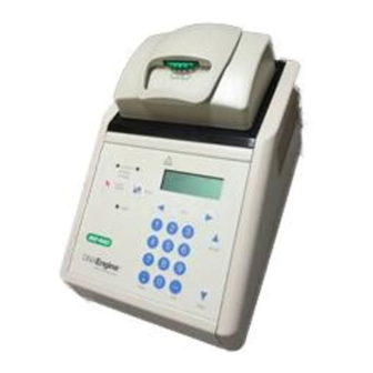
- Page 1 ® DNA Engine Thermal Cycler Operations Manual Version 4.0 PTC-200 DNA Engine Cycler...
- Page 2 DNA Engine ® Peltier Thermal Cycler PTC-0200 DNA Engine Cycler Operations Manual Version 4.0...
- Page 3 Copyright ©2005, Bio-Rad Laboratories, Incorporated. All rights reserved. Reproduction in any form, either print or electronic, is prohibited without written permission of Bio-Rad Laboratories, Inc. Alpha, Chill-out, Concord, Dual Alpha, DNA Engine, DNA Engine Tetrad, Hard-Shell, Hot Bonnet, Microseal, Moto Alpha, Multiplate, Power Bonnet, Remote Alpha Dock, Slide Chambers, and Tetrad are trademarks of Bio-Rad Laboratories, Inc.
-
Page 4: Table Of Contents
Table of Contents Explanation of Symbols ...........iv Safety Warnings . -
Page 5: Explanation Of Symbols
Explanation of Symbols CAUTION: Risk of Danger! Wherever this symbol appears, always consult note in this manual for further information before proceeding. This symbol identifies components that pose a risk of personal injury or damage to the instrument if improperly handled. CAUTION: Risk of Electrical Shock! This symbol identifies components that pose a risk of electrical shock if improperly handled. - Page 6 Safe Use Guidelines The DNA Engine instruments are designed to be safe to operate under the following conditions: • Indoor use • Altitude up to 2000 m • Ambient temperature 5–31°C • Maximum relative humidity 90%, noncondensing • Transient overvoltage per Installation Category II, IEC 664 •...
-
Page 7: Documentation Conventions
Documentation Conventions Typographic Conventions The names of keyboard keys are set in double angle brackets: Example «Proceed» Items in programming menus are italicized: Example Select Edit from the Main Menu. Graphic Conventions The programming screens displayed in the LCD window are represented by a box containing four lines of text: Example Run: 2-STEP... -
Page 8: Introduction
Introduction Meet the DNA Engine Thermal Cycler ........1-2 Using This Manual . - Page 9 DNA Engine Operations Manual Meet the DNA Engine ® Thermal Cycler Thank you for purchasing a Bio-Rad PTC-0200 DNA Engine thermal cycler. Designed by a team of molecular biologists and engineers, the DNA Engine will meet your needs for a versatile, easy-to-use, reliable, and compact programmable thermal cycler.
- Page 10 Introduction Important Safety Information Safe operation of the DNA Engine begins with a complete understanding of how the machine works. Please read this entire manual before attempting to operate the DNA Engine. Do not allow anyone who has not read this manual to operate the machine. The DNA Engine can generate enough heat to inflict serious burns and can deliver strong electrical shocks if not used according to the instructions in this manual.
-
Page 12: Layout And Specifications
Layout and Specifications Front View .............2-2 Control Panel . -
Page 13: Front View
DNA Engine Operations Manual Front View Thumbwheel Alpha ™ unit, lid closed (Figure 2-1) Control panel Air exhaust vents (also on other side) Air intake vents Control Panel Block key (Figure 2-2) LCD window Block status lights Instant incubation key Left and right selection keys Power light... -
Page 14: Back View
Layout and Specifications Back View (Figure 2-3) Alpha unit Air exhaust vents (also on other side) Alpha unit handle Air intake vents Power cord jack RS-232 port IEEE-488 port Parallel printer port Bottom View Air intake vents (Figure 2-4) Front Back Tech Support: 1-800-4BIORAD •... -
Page 15: Alpha Units
DNA Engine Operations Manual Alpha Units Single-Block Models 60V Alpha unit: Holds 60 x 0.5 ml tubes 96V Alpha unit: Holds 96 x 0.2 ml tubes or one 96-well microplate 384 Alpha unit: Holds one 384-well microplate or one 96-well microplate Dual-Block Models 30/30 Dual Alpha... -
Page 16: Specifications
Layout and Specifications Specifications Thermal range: –5° to 105°C, but no more than 30°C below ambient temperature (4° to 100°C for the Slide Chambers Alpha unit) Thermal accuracy: ±0.3°C of programmed target at 90°C, NIST-traceable Thermal uniformity: ±0.4°C well-to-well within 30 seconds of arrival at 90°C (for most Alpha units;... -
Page 17: Gradient Specifications
DNA Engine Operations Manual Gradient Specifications (96V Alpha module only) Accuracy: +0.3°C of programmed target at end columns, 30 seconds after the timer starts for the gradient step, NIST–traceable Column uniformity: +0.4°C, well–to–well within column, within 30 seconds of reaching target temperature Gradient calculator accuracy: +0.4°C of actual well temperature Lowest programmable temp: 30°C Highest programmable temp: 105°C... -
Page 18: Installation
Installation Packing Checklist ............3-2 Setting Up the DNA Engine Cycler . -
Page 19: Packing Checklist
DNA Engine Operations Manual Packing Checklist After unpacking the DNA Engine ® cycler, check to see that you have received the fol- lowing: • One DNA Engine base • One Alpha ™ unit (more if additional units were ordered) • Two spare fuses •... -
Page 20: Power Supply Requirements
Installation • Protection from excessive heat and accidental spills (Do not place the DNA Engine cycler near such heat sources as radiators, and protect it from danger of having water or other fluids splashed on it, which can cause shorting in its electrical cir- cuits.) Power Supply Requirements The DNA Engine cycler requires 100–240 VAC, 50–60 Hz, and a grounded outlet. -
Page 21: Ensuring That Air Is Cool Enough
DNA Engine Operations Manual Ensuring That Air Is Cool Enough • Do not position two or more DNA Engine cyclers (or other thermal cyclers) so that the hot exhaust air of one blows directly into the air intake vents of another. •... - Page 22 Operation Turning the DNA Engine Cycler On .........4-2 Understanding the Main Menu .
-
Page 23: Turning The Dna Engine Cycler On
In most cases a self-test of the heat pumps will begin running (see note below). Its progress is tracked on a screen in the LCD window: PTC-200: S e l f t e s t i n g This screen disappears in 1 minute. -
Page 24: Operation
Operation Using the Control Panel The control panel (see fig. 2-2) includes operation keys, status indicator lights, an LCD window for displaying programming and machine status text, and a numeric keypad for entering values into programs. Operation Keys • Select keys (left and right arrows): Move the cursor one space or option to the left or right in the LCD window;... -
Page 25: Operating Alpha Units
DNA Engine Operations Manual Operating Alpha Units Note: Operation of the Slide Chambers ™ Alpha unit will not be discussed, owing to the many differences between this type of Alpha unit and the others. Please see the Slide Chambers Operations Manual for operating instructions. Note: Moto Alpha ™... -
Page 26: Removing An Alpha Unit
Operation Removing an Alpha Unit 1. Turn the DNA Engine cycler off (see the Caution below). 2. Pull upward on the handle. When the lock releases, you will hear a click, and the Alpha unit will slide a little toward the back of the DNA Engine cycler. The elec- trical connectors of the Alpha unit and the DNA Engine cycler are now disengaged, so there is no danger of electrical shock. -
Page 27: Selecting The Correct Sample Vessel
DNA Engine Operations Manual Selecting the Correct Sample Vessel The DNA Engine cycler’s wide variety of interchangeable Alpha units affords you great scope in choosing sample vessels. Keep in mind that differences in tube and plate com- position and wall thickness among the many brands available can affect reaction performance. -
Page 28: Sealing Sample Vessels
Operation Sealing Sample Vessels To avoid changing the concentration of reactants, steps must be taken to prevent the evaporation of water from reaction mixtures during thermal cycling. Only a layer of oil or wax will completely prevent evaporation from the surface of the reaction fluid. However, an adequate degree of protection can be achieved by sealing vessels with caps, film, adhesive seals, or mats, then cycling the samples using the heated lid to prevent condensation. -
Page 29: Adjusting The Hot Bonnet Lid's Pressure
DNA Engine Operations Manual Microseal ® ‘A’ film offers a quick alternative to sealing microplates or arrays of tube strips. This film is specially designed to seal tightly during cycling, yet release smoothly to minimize the risk of aerosol formation and cross-contamination of samples. Microseal ‘A’... -
Page 30: Loading Sample Vessels Into The Block
Operation 4. Close the Hot Bonnet lid by pressing down on the top lever. Turn the thumbwheel clockwise to lower the Hot Bonnet inner lid onto the loaded microplate/tubes. The thumbwheel turns easily at first since the inner lid has not yet come into contact with anything. -
Page 31: Using Oil To Thermally Couple Sample Vessels To The Block
DNA Engine Operations Manual Using Oil to Thermally Couple Sample Vessels to the Block With two exceptions (see below), Bio-Rad does not recommend using oil to thermally couple sample vessels to the block, for the following reasons: • Calculated-control protocols do not run accurately when oil is used. •... -
Page 32: Appendix 4-A: Tube, Microplate, And Sealing System Selection Chart
Operation Appendix 4-A Tube, Microplate, and Sealing System Selection Chart 4 Reaction vessel fits block/sealing option fits reaction vessel without modification. # Reaction vessel/sealing option can be cut to fit. Reaction Vessels Sealing Options for Oil-Free Cycling Bio-Rad Thermal Cycler Blocks 60/30 Description Bio-Rad... -
Page 33: Appendix 4-B: Safety Warning Regarding Use Of
DNA Engine Operations Manual Appendix 4-B Safety Warning Regarding Use of S Nucleotides Some researchers have experienced a problem with radioactive contamination when using S in thermal cyclers. This problem has occurred with all types of reaction vessels. The Problem When S nucleotides are thermally cycled, a volatile chemical breakdown product forms, probably SO... - Page 34 Operation If mild cleaning agents do not remove radioactivity, harsher cleaners may be used. Users have suggested the detergent PCC-54 (Pierce Chemical Co., Rockford, Illinois; Pierce Eurochemie B.V., Holland), Micro Cleaning Solution (Cole-Parmer, Niles, Illinois), and Dow Bathroom Cleaner (available in supermarkets). Caution: Harsh cleaning agents are corrosive to aluminum and must never be used on bare aluminum blocks.
- Page 36 Running Protocols Running a Protocol ............5-2 Choosing a Stored Protocol to Run .
-
Page 37: Running A Protocol
DNA Engine Operations Manual Running a Protocol Running a protocol on the DNA Engine ® cycler involves three steps: 1. Choosing a stored protocol to run. 2. Choosing a block to run it on, if a Dual Alpha ™ unit is installed. 3. -
Page 38: Running Protocols
Running Protocols In either instance, after you press «Proceed», a screen similar to the following example will be displayed: Run: 2-STEP Vessel Type: _TUBES Plate The top line of the screen will identify the selected protocol (2-STEP in the example). The other lines on the screen will request information needed to set up the temperature control method (explained below). -
Page 39: Setting Up A Calculated-Control Protocol
DNA Engine Operations Manual Setting Up a Calculated-Control Protocol Three screens will be presented: • A screen asking for sample vessel information: Run: 2-STEP Vessel Type: _TUBES Plate Select from the options shown (may include tubes, plates, and slides), then press «Proceed». -
Page 40: Reading The Runtime Screen
Running Protocols Reading the Runtime Screen During a protocol run, a runtime screen will be displayed: Run: 2-STEP 1= 92.0 f o r 0 : 0 5 Cycle: 1 Calc: 68.0 The screen lists the protocol name (2-STEP in the example above), protocol step that is running (1), cycle number (1), method of temperature control (Calc), and the block temperature for block-control protocols, and the calculated sample temperature for calculated-control protocols (68.0°). -
Page 41: Switching Between The Runtime Screen And The Main Menu
DNA Engine Operations Manual Switching Between the Runtime Screen and the Main Menu Press «Block» to toggle between the runtime display and the Main Menu. This allows you to edit a stored program, enter a new one, print a program, run another protocol on a dual-block Alpha unit or networked DNA Engine cycler, or use the file utilities, while the protocol runs. -
Page 42: Manually Stepping Through A Protocol
Running Protocols To print the protocol as it runs, select Yes, then press «Proceed». Note: If no printer is connected to the machine, the screen allowing you to select printer output is not displayed at all. Manually Stepping Through a Protocol Once a protocol is running, pressing «Proceed»... -
Page 43: Stopping A Running Protocol
DNA Engine Operations Manual Stopping a Running Protocol Press either «Stop» or «Cancel» to stop a running protocol. A cancellation confirmation screen will be displayed: Run: 2-STEP Stop 2-STEP? Yes _NO Select Yes, then press «Proceed» to cancel the protocol. The total run time for the protocol will be displayed: Run: 2-STEP PROGRAM CANCELED... -
Page 44: Using The Instant Incubation Feature
Running Protocols Using the Instant Incubation Feature The DNA Engine cycler may be converted to a constant-temperature incubator by pressing «Instant Incubate». A screen allowing use of the heated lid will be displayed: INCUBATE: Use heated lid? Yes _No Use the «Select» keys to enable or disable the heated lid, then press «Proceed». A screen allowing entry of the incubation temperature will be displayed. - Page 46 Creating Programs The Elements of a Program ..........6-2 Designing a New Program .
-
Page 47: The Elements Of A Program
DNA Engine Operations Manual The Elements of a Program DNA Engine ® cycler programs consist of a series of steps encoding a protocol. These steps are run using one of two possible temperature control methods: calculated con- trol or block control. Programs may contain five types of steps. -
Page 48: Creating Programs
Creating Programs Designing a New Program Translating a Protocol into a Program Until you are completely familiar with programming the DNA Engine cycler, you may find it helpful to first translate the protocol into DNA Engine cycler program steps and options on paper. -
Page 49: Choosing A Temperature Control Method
DNA Engine Operations Manual Choosing a Temperature Control Method The DNA Engine cycler can control block temperature in two possible ways, each of which has different implications for the speed and accuracy of sample heating: • Calculated control: The DNA Engine cycler adjusts the block’s temperature to maintain samples of a specific volume in a specific vessel type at programmed tem- peratures. -
Page 50: Modifying Block-Control Programs For Calculated Control
Creating Programs Modifying Block-Control Programs for Calculated Control Block-control programs can be changed to calculated control by subtracting at least 15–20 seconds from each temperature step. Some empirical testing may be required to adjust modified programs for optimum performance. Modifying a Program Designed for a Different Machine The ramp programming step can be used to adapt programs designed for thermal cyclers with slower maximum heating and cooling rates than the DNA Engine cycler. -
Page 51: Naming The Program
DNA Engine Operations Manual Naming the Program Name the program an eight-character word consisting of any combination of letters (Roman and Greek), numbers, punctuation marks, or Japanese Katakana. Press the right «Select» key to scroll forward and the left «Select» key to scroll backward through the alphabets and characters available, which are presented in this order: Roman alphabet, selected Greek letters, punctuation marks, numbers. -
Page 52: Entering A Temperature Step
Creating Programs Use this menu to enter each step of the program: • Temp enters a temperature step. • Gradient enters a Gradient step. • GoTo enters a GoTo step (note: since a protocol cannot begin with a GoTo step, GoTo does not appear on the initial Enter Menu). •... -
Page 53: Entering A Gradient Step
DNA Engine Operations Manual Enter the hold time for the step (30 seconds is used in the example below): Enter: CUSTO M 1 1= 92.0 Time: Note: If a hold time of zero (0) is entered, the DNA Engine cycler will hold the block atthe target temperature indefinitely. - Page 54 Creating Programs The gradient screen will appear: Enter: CUSTO M 1 Lower Temp C : Enter the lower limit temperature (for the purposes of this example, 50°), then press «Proceed». The upper temperature screen will appear: Enter: CUSTO M 1 50.0 Upper Temp C : Enter the upper temperature (for the purposes of this example, 70°), then press «Proceed».
-
Page 55: Editing A Gradient Step
DNA Engine Operations Manual Editing a Gradient Step To edit a gradient step, select Edit from the Main Menu. The program will be displayed as follows: List: CUSTO M 1 1= 92.0 f o r 0 : 2 0 2= 50.0 t o 70.0 f o r 0 : 3 0 Use the «Select»... -
Page 56: Using The Gradient Calculator
Creating Programs Using the Gradient Calculator The gradient calculator predicts, for a given gradient, the temperatures for each of the twelve wells along the long-axis of the sample block. These temperatures will be predicted from an algorithm as a steady-state temperature of the block and the sample. -
Page 57: Entering A Ramp Step
DNA Engine Operations Manual Entering a Ramp Step To enter a ramp step, select Ramp from the Enter Menu. The first Ramp screen will be displayed: Enter: CUSTO M 1 Rate C / s : _ The second line of this screen shows the number of the step being programmed (3 is used in the example above). -
Page 58: Entering A Goto Step
Creating Programs Select one of the displayed choices, then press «Proceed»: • Yes accepts the step and displays the Enter Menu again. Use the Enter Menu to enter the next step in the program. • No allows reentry of the ramp rate and finish temperature. •... -
Page 59: Entering The End Step
DNA Engine Operations Manual Enter the additional number of times the program should cycle back to the step (3 is used in the example below): Enter: CUSTO M 1 3=GoTo 1 Addt n l c y c l e s : Press «Proceed». -
Page 60: Modifying A Program Step With The Options
Creating Programs If you have created custom folders for your programs (see chapter 8), choosing Yes brings up a screen listing the folders: Save Program in: <MAIN> <FOLDER> <FOLDER2> Select the folder you want to store the program in, then press «Proceed». The pro- gram will be stored in the folder, and the Main Menu will be displayed. -
Page 61: Entering An Extend Option
DNA Engine Operations Manual The temperature step being modified appears on the second line of this screen. The plus sign on the third line means that the screen is set up to enter a progressive increase in temperature per cycle. Press «–» to switch to a minus sign, allowing entry of a progressive decrease in temperature. - Page 62 Creating Programs Enter the numerical value of the increase or decrease in hold time (1.0 is used in the example below): Enter: CUSTO M 1 1= 92.0 f o r 0 : 3 0 Sec / c y c l e : + 1 Press «Proceed».
-
Page 63: Revising During Programming
DNA Engine Operations Manual Revising During Programming To change values in a program you are entering, follow the procedures described below. This editing method should be used to change just a few values at a time. To make many changes, or to delete or add entire steps, use Edit mode (see chapter 7). To Change the Last Value Entered or Menu Option Chosen Press «Cancel». -
Page 64: Deleting A Program
Creating Programs To add an option to a step, move the cursor to the step number, then press «Proceed». The Edit Menu will be displayed: Enter: CUSTO M 1 2 = 9 2 . 0 f o r 0 : 4 0 _ E d i t I n s e r t St e p : Option Delete Select Option, then press «Proceed», and follow the procedure for adding an option. -
Page 66: Editing Programs
Editing Programs Editing a Stored Program ..........7-2 Initiating Editing . -
Page 67: Editing A Stored Program
DNA Engine Operations Manual Editing a Stored Program The DNA Engine ® cycler’s editing tools, available through Edit on the Main Menu, make it easy to extensively edit stored programs by: • Changing individual values in program steps • Adding new steps •... -
Page 68: Editing The Program
Editing Programs Editing the Program The first editing screen displays the two temperature control methods. The program’s current temperature control method is displayed in all-capital letters: Enter: CUSTO M 1 Control method: Block _CALCULAT ED Select a different temperature control method if desired, then press «Proceed» The first three lines of the program will be displayed: Edit: CUSTO M 1 _1= 92.0 f o r 0 : 1 0... -
Page 69: Inserting A New Step
DNA Engine Operations Manual Inserting a New Step To insert a new step, select Insert from the Edit Menu, then press «Proceed». The Enter Menu will be displayed for the new step (a new step 2 is added in the example below): Edit: CUSTO M 1 St e p 2= _T E M P GoTo Ramp... -
Page 70: Cancelling Editing Changes
Editing Programs • End saves the changes and displays the Main Menu. This ends the editing session. • Insert allows another step to be added just before the End step. Cancelling Editing Changes To cancel all editing changes made to a program, use the «Select» keys to move the cursor to any step number, then press «Cancel». - Page 72 Using the Utilities Locating a Stored Program ..........8-2 File Utilities .
-
Page 73: Locating A Stored Program
DNA Engine Operations Manual Locating a Stored Program Many of the DNA Engine ® cycler’s utilities require you to locate a program stored in the machine. The actions necessary to do this depend on whether your programs have been stored in the <MAIN> folder or in custom folders. •... -
Page 74: Using The Utilities
Using the Utilities Creating a Folder The DNA Engine cycler’s memory can hold up to 11 folders, including the <MAIN> folder. New programs are placed in the <MAIN> folder by default unless a different folder is specified. To create a folder, select Folder from the Files Menu, then press «Proceed». A naming screen will be displayed: New Folder: Name: A... -
Page 75: Deleting A Folder
DNA Engine Operations Manual Deleting a Folder A folder must be empty before it can be deleted. After all programs have been moved or deleted from the folder, select Delete from the Files Menu, then press «Proceed». A list of all folders in the machine will be displayed. Select the folder to be deleted, then press «Proceed». -
Page 76: Renaming A Program
Using the Utilities Renaming a Program To rename a program, select Rename from the File Menu, then press «Proceed». Locate the program to be renamed (see “Locating a Stored Program,” p. 8-2), then press «Proceed». A naming screen will be displayed: Rename: CUSTO M 1 New name: A... -
Page 77: Viewing A Program In The Lcd Window
DNA Engine Operations Manual Viewing a Program in the LCD Window To view a program in the LCD window, select List from the Main Menu, then press «Proceed». Locate the program to be viewed (see “Locating a Stored Program,” p. 8-2), then press «Proceed». -
Page 78: Setup Utilities
Using the Utilities Setup Utilities Use these utilities, available from the Setup Menu, to accomplish the following tasks: • Choose a remote port and a printer port • Choose a temperature control method for the Hot Bonnet heated lid • Look up the DNA Engine cycler’s software version number To display the Setup Menu, select Setup from the Main Menu, then press «Proceed»: Setup: _ R E M O T E... -
Page 79: Choosing A Printer Port
DNA Engine Operations Manual The instrument’s current address will be displayed. To change it, enter a number from 0–30, then press «Proceed». The remote port assignment will change to IEEE-488, the address number will be assigned to the instrument, and the Main Menu will be displayed. -
Page 80: Determining The Software Version Number
Using the Utilities • Constant: Keeps the inner lid at a specified temperature (°C). The DNA Engine cycler is set for the tracking mode at the factory, using an offset of 5°C, which should be adequate for most reactions. The constant mode is provided for unusual reactions requiring the inner lid to be hot at all times. - Page 81 DNA Engine Operations Manual 8-10 Tech Support: 1-800-4BIORAD • 1-800-424-6723 • www.bio-rad.com...
-
Page 82: Networking
Networking Overview of Networking ..........9-2 Networking Instruments without a Computer . - Page 83 DNA Engine Operations Manual Overview of Networking Up to 15 instruments consisting of any combination of DNA Engine ® DNA Engine Tetrad ) cyclers may be networked, with or without a computer as the ® controller. When networking with a computer, all the instruments are controlled from the computer’s keyboard.
- Page 84 Networking Select IEEE-488, then press «Proceed». The remote addressing screen will be displayed: Remote: Serial _IEEE-448 Address (0-30): 0 Enter an address number for the instrument. Set the controller DNA Engine cycler’s address to 0. Give the other instruments in the network any number from 1 to 30. Press «Cancel»...
- Page 85 DNA Engine Operations Manual If the right or left block of a dual-block Alpha unit has been selected, an A or B will appear after the address number (e.g., 7-3A for the right-hand block in a Dual Alpha unit loaded into quadrant 3 of a DNA Engine Tetrad at address 7. See figure 12-1 for a diagram of the layout of quadrants in the DNA Engine Tetrad cycler).
- Page 86 Networking The IEEE-488 GPIB Remote Interface To connect DNA Engine (and DNA Engine Tetrad) cyclers in a computer-controlled IEEE-488 network, the computer must be equipped with an IEEE-488 (GPIB) inter- face card. Connect the instruments and assign addresses as described under “Networking Instruments Without a Computer”...
-
Page 88: Maintenance
Maintenance Cleaning the DNA Engine Cycler ......... 10-2 Cleaning the Chassis and Block . -
Page 89: Cleaning The Dna Engine Cycler
DNA Engine Operations Manual Cleaning the DNA Engine ® Cycler Cleaning the Chassis and Block Clean the outside of the DNA Engine cycler and Alpha ™ unit with a damp, soft cloth or tissue whenever something has been spilled on it or the chassis is dusty. A mild soap solution may be used if needed. -
Page 90: Cleaning Radioactive Or Biohazardous Materials Out Of The Block
Maintenance Cleaning Radioactive or Biohazardous Materials out of the Block When cleaning instruments that have been running radioactive or biohazardous reac- tions, consult your institution’s radiation safety officer or biosafety officer regarding cleaning methods, monitoring, and disposing of contaminated materials. Changing the Fuses The circuits in the DNA Engine cycler are protected by two fuses (6.3A fast-acting, 5x20mm). -
Page 92: Troubleshooting
Troubleshooting Error Messages ............11-2 Problems Related to Protocols . - Page 93 DNA Engine Operations Manual Error Messages Note: The DNA Engine ® and DNA Engine Tetrad ® software is highly sensitive with respect to block and heat-sink errors. When such errors messages occur, try restarting the protocol. If the message fails to reappear, proceed as usual. Error Message Cause Action...
- Page 94 Troubleshooting Error Message Cause and Result Action Calc Control, Probe Runtime error indicating a gradient Change to Calc control mode. Mode Invalid step is being programmed under Probe Control mode. Gradient Fault, Service Displayed at end of run. Indicates Alpha unit and / or base needs Alpha soon.
- Page 95 DNA Engine Operations Manual Error Message Cause and Result Action HS Sensor Fault, Alt Alpha unit heat sink sensor is not Alpha unit needs servicing soon. Control Mode functioning properly, so machine Contact Bio-Rad or your local dis- has begun estimating heat sink tributor.
- Page 96 Troubleshooting Error Message Cause and Result Action PS Overheated, Machine is not getting enough air, Make sure that machine is getting Program Terminated or air being taken in is warmer enough air and that temperature of than 31°C. air being taken in is 31°C or cooler (see p.
- Page 97 DNA Engine Operations Manual Problems Related to Protocols Following is a general description of some common problems related to the protocols and reaction components in sequencing and amplification applications. For a more detailed discussion of protocols and reactions, see Current Protocols in Molecular Biology (F.
- Page 98 Troubleshooting Problem Cause Action No reaction products Wrong protocol used. Re-run reaction using correct obtained. protocol. Protocol contains a wrong value. Use List utility to check protocol’s temperature control method, tem- peratures, and times. Reaction component omitted from Check reaction assembly protocol, mixture.
- Page 99 DNA Engine Operations Manual Problems Related to Environmental Conditions, Setup, and Maintenance Problem Cause Action Frequent shutdowns Machine is not receiving enough Make sure air intake vents ar not due to overheating. air. obstructed by dust, debris, or Frequent “Slow Block paper.
- Page 100 Appendix A: Warranty Information The DNA Engine ® (PTC-0200) thermal cycler is warranted against defects in materials and workmanship. For specific warranty information, contact your local Bio-Rad office. If any defects should occur during the warranty period, Bio-Rad will replace the defective parts without charge.
-
Page 101: Appendix B: Factory-Installed Protocols
Appendix B: Factory- Installed Protocols 2-step Fast PCR protocol using Standard 2-step PCR protocol iTaq ™ polymerase STD-2 iTAQ-FST Step Temp Time 4:00 Step Temp Time GOTO 2, 29X GOTO 2, 34X Standard 3-step PCR protocol 2-step PCR protocol using iProof ™... - Page 102 DNA Engine Operations Manual 3-step nested primer protocol 2-step RT PCR protocol NEST PR3 RTPCR-2 Step Temp Time Step Temp Time 60:00 4:00 5:00 GOTO 3, 39X GOTO 2, 39X 7:00 7:00 3-step RT PCR protocol GOTO 8, 39X RTPCR-3 7:00 60:00 5:00...
-
Page 103: Index
Index Air supply requirements ensuring adequate air supply 3-3 ensuring air is cool enough 3-4 troubleshooting problems with 3-4 Alpha units closing 4-5 installing 4-4 models 2-4 opening 4-5 removing 4-5 Baud rate, setting 8-7 Beep option. See Programs: options, types of Bleach, using in block 10-2 Chill-out liquid wax 4-7 Cleaning... - Page 104 DNA Engine Operations Manual keys 4-3 lights 4-3 using 4-3 Documentation conventions graphic vi terminology vi typographic vi Electromagnetic interference v Environmental requirements 3-2–3-3 Error messages 11-2 Explanation of symbols iv Extend option. See Programs: options, types of FCC warning v Fuses changing 10-3 Hot Bonnet lid...
- Page 105 Index front view 2-2 Menus Edit Menu 7-2 Enter Menu 6-5 Files Menu 8-2 Main Menu 4-2 Options Menu 6-5 Setup Menu 8-7 Microseal ‘A’ film 4-8 ‘B’ adhesive seals 4-8 ‘F’ foil 4-8 'P'/'P+' pads 4-8 Moto Alpha unit 2-4 Networking general information 9-2 with computer as controller 9-4...
- Page 106 DNA Engine Operations Manual Passwords. See Utilities: files: assigning password to folder Ports 2-5, 4-3 IEEE-488 2-3 parallel (printer) 2-3 RS-232 2-3 Power cord location of jack 2-3 plugging in 3-2 Power supply requirements 3-3 acceptable power cords 3-3 Programming choosing a temperature control method 6-6 deleting a program 6-19 entering steps...
- Page 107 Index using GoTo steps to shorten programs 6-3 editing 7-2, 7-3 adding an option 7-4 cancelling editing changes 7-5 deleting step 7-4 inserting new step 7-4 saving edited program 7-4 finding in machine 5-2, 7-2, 8-2 options, types of 6-2, 6-15 program steps, types of 6-2 renaming.
- Page 108 DNA Engine Operations Manual Sample vessel selection chart 4-11 Sample vessels ensuring good thermal contact 4-10 loading into block 4-9 sealing reason for 4-7 with Hot Bonnet lid and caps/film 4-7 with oil or wax 4-7 selection 4-6 0.2 ml tubes 4-6 0.5 ml tubes 4-6 microplates 4-6 use of oil to improve thermal contact with block 4-10...
- Page 109 Index printing a program 8-6 renaming programs 8-5 viewing a program in LCD window 8-6 setup 8-7 choosing a printer port 8-8 choosing a remote port 8-7 choosing a temperature control method for the Hot Bonnet lid 8-8 determining software version number 8-9 Warranty information A-1 Tech Support: 1-800-4BIORAD •...
- Page 110 DNA Engine Dyad and Dyad Systems Operations Manual In-8 Tech Support: 1-800-4BIORAD • 1-800-424-6723 • www.bio-rad.com...
-
Page 111: Declaration Of Conformity
Declaration of Conformity Bio-Rad Laboratories, Inc., 1000 Alfred Nobel Drive, Hercules, California, 94547, U.S.A., declares that the product PTC0200, The DNA Engine ® Thermal Cycler to which this declaration relates, is in conformity to the following standards or normative documents. IEC61010-1 EN61326: CLASS A following the provisions of the 73/23/EEC, 89/336/EEC &... - Page 113 Technical Service: Call your local Bio-Rad office, or in the U.S. call 1-800-4BIORAD (1-800-424-6723). Bio-Rad Laboratories, Inc. Life Science Web site www.bio-rad.com USA (800) 4BIORAD Australia 02 9914 2800 Austria (01)-877 89 01 Belgium 09-385 55 11 Brazil 55 21 2527 3454 Canada (905) 712-2771 China (86 21) 6426 0808 Czech Republic + 420 2 41 43 05 32 Denmark 44 52 10 00 Finland 09 804 22 00 Group France 01 47 95 69 65 Germany 089 318 84-0 Greece 30 210 777 4396 Hong Kong (852) 2789 3300 Hungary 36 1 455 8800...
Need help?
Do you have a question about the PTC-200 and is the answer not in the manual?
Questions and answers