
Related Manuals for BIO RAD 680


Summary of Contents for BIO RAD 680
- Page 1 Model 680 Microplate Reader Instruction Manual Catalog Numbers 168-1000 168-1001 168-1002 168-1003...
- Page 2 Bio-Rad shall not be liable for any incidental, special, or consequential loss, damage, or expense directly or indirectly arising from the use of the Model 680 Microplate Reader. Bio-Rad makes no warranty whatsoever in regard to products or parts furnished by third parties, such being subject to the warranty of their respective manufacturers.
- Page 3 Regulatory Notices Electro Magnetic Compatibility: This instrument is designed to meet the Class-A emissions and immunity levels of the EN61326 product family standard for the CE mark. This rating requires that it only be used in a laboratory environment. Note: This instrument has been tested and found to comply with the limits for a Class A digital device, pursuant to Part 15 of the FCC rules.
-
Page 4: Table Of Contents
Table of Contents Introduction ....................1 Section 1..1.1 Description and accessories for Model 680 Microplate Reader ......2 Product Description ..................3 Section 2..2.1 Contents of Shipping Carton ................3 2.2 External Features..................4 2.3 Membrane Keypad ..................5 Section 3. -
Page 5: Introduction
Hard copy reports can be produced by an optional on-board thermal printer or external printer. The Model 680 reader can also be controlled by the Windows’ based Microplate Manager software (catalog number 170-9520) program, through its built-in RS232C serial interface device. -
Page 6: Description And Accessories For Model 680 Microplate Reader
Model 680 microplate reader 168-1001 Model 680 microplate reader with temperature control 168-1002 Model 680 microplate reader with internal printer 168-1003 Model 680 microplate reader with temperature control and internal printer 168-1011 405 nm filter 168-1013 415 nm filter 168-1020... -
Page 7: Product Description
Section 2. Product Description Contents of Shipping Carton The shipping carton contains the following items: Model 680 Microplate Reader, with 415nm, 450nm, 490nm and 655nm interference filters installed on the filter wheel. Power cord Serial PC Cable Spare fuse Dust cover... -
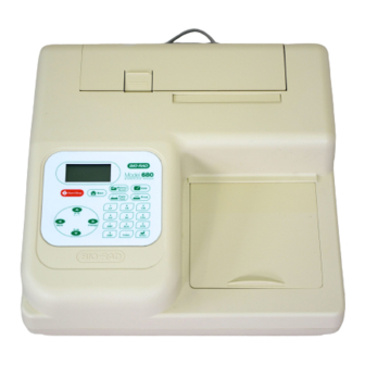
Page 8: External Features
External Features 1. Release latch for rear cover 4. Rear cover 2. Liquid crystal display (LCD) 5. Printer slot (when optional built-in printer is installed) 3. Membrane keypad 6. Reading chamber door 7. RS-232C serial interface 11. Printer port (only when optional built-in printer is not installed) 8. -
Page 9: Membrane Keypad
Membrane Keypad Memo ry E dit Recall Sta rt/ Sto p Ma in P ap er P rin t Feed Back Ch ange S T D FUNC 1. Main Returns to MAIN SCREEN. 2. Start/Stop Initiates plate reading using current active protocol. Stops plate reading and printing. -
Page 10: Instrument Set-Up
Section 3. Instrument Set-up Initial Start-up Place the instrument on a clean, sturdy table or bench. It is important to keep the instrument in a clean, relatively dust free environment to ensure optimal performance. Connect the power cord to the back of the instrument. Before connecting the instrument to the main electrical supply, check that the AC voltage is appropriate for the instrument. -
Page 11: Operation
Operation Instrument Overview The Model 680 Microplate Reader has built-in software that allows the user to set the plate reading and data analysis conditions as a protocol data, read a microplate under the defined reading conditions, and get the printout reports from the internal or external printer. The software communicates through the 4-line, 20-character LCD and is controlled through the instrument's membrane keypad. - Page 12 Operation flow when End point protocol selected Not Use Edit Ranged Cutoff Cutoff Values setting Constant Single Cutoff Gray zone setting when single Cutoff Ranged Cutoff Cutoff Control setting Control Single Cutoff Gray zone setting when single Cutoff Cutoff 12 choices of Formula Coefficient setting of selected formula cutoff formula...
- Page 13 Operation flow when Kinetic protocol selected Edit Number of reads (2-30), Start delay time (0-999) Reading Reading interval time Inter Shake (First/Every/disable), Speed (High, Low, Mid), Time Shaking Mode Single / Dual Wavelength Ph.mode Read Speed (Fast/Step) Speed Disable/Enable Temperature Incu CC Limit (correlation coefficient limit) GALT factor k input (0- 9999)
-
Page 14: Functions Overview
4.2.2 Security password The Model 680 Microplate Reader requires user login with password. This security feature helps to prevent any unwarranted modifications to the analysis conditions/protocols and data stored in the instrument, and identifies operator on reports. The reader has two user settings, the Administrator and the Common user. -
Page 15: Limits
in this memory. The first time the instrument is turned on, or after a battery failure, the following default information will be held in the memory. Both of Administrator and Common user security password are set to "00000". Laboratory name is "Bio-Rad Laboratories". All wavelength values of the filters are set to "---"... - Page 16 Blank mean = X/n S.D. = [{X^2 – n*(Blank mean)^2}/{n-1}]^1/2 Where: S.D. = Standard deviation X = Sum total of the raw absorbance for each blank X^2 = Sum total of the squared raw absorbance for each blank n = Number of blanks Limit report The Limit report provides a qualitative YES/NO report.
- Page 17 Upper cutoff absorbance = Positive absorbance + ((Gray zone/100) * Positive absorbance) Lower cutoff absorbance = Positive absorbance – ((Gray zone/100) * Positive absorbance) For units not designated "Abs", the absorbance value of each well is converted to the concentration value using the curve fit constants of the curve fit report. If the concentration of a well is within the gray zone value of the positive cutoff value, the well is scored "*".
- Page 18 (-). Curve fit report The Curve fit report provides a regression analysis based on the absorbance values of a series of standards. There are ten types of curve fits supported with the onboard software on Model 680 microplate readers:...
- Page 19 5P Logistic Rodbard 4P Logistic Rodbard iii. 5P Logistic Cook-Wilkenson iv. 4P Logistic Cook-Wilkenson 5P Exponential vi. Sigmoid Logistic vii. Linear regression viii. Quadratic regression ix. Cubic spline Point To Point regression The onboard software calculates the best fit of the defined curve between each set of two consecutive data points in the standard curve of absorbance vs.
-
Page 20: Rs-232C Interface
4.2.6 RS-232C Interface The Model 680 Microplate Reader has a built-in bi-directional RS-232C interface (9 pin D-sub connector, Bio-Rad catalog number: 168-1005). This allows external computers to control the instrument. When an external computer is in control of the microplate reader, the printer and the membrane keys, except for the "Start/Stop"... -
Page 21: Printer
4.2.7 Printer The Model 680 Microplate Reader has a built-in printer interface connector (25 pin D-sub) or an optional factory built-in printer. The printer interface connector allows the user to connect an external printer for the printout of reports or protocol. This external printer interface is based upon Centronics interface standards. -
Page 22: Detailed Operation
Detailed Operation 4.3.1. Initial Start-up Self-Diagnosis Self-diagnosis Model 680 This screen will appear upon power-up and during self-diagnosis. Date and Time shall Microplate Reader also be indicated on this screen. 13:05 18/09/01 Initialization Initializing reader After self-diagnosis, the system shall initialize all the hardware. -
Page 23: Configuring The System
4.3.2. Configuring the system Note: To return to the previous screen, use the back/left arrow key. Edit Menu Edit Menu » Protocol •Lab.name •Security •SaveSTDC This menu can be accessed by pressing the Edit key in the MAIN SCREEN. •Filters •Printer •Date set Security Menu... - Page 24 Use the Up and Down arrow keys to select from “A” to “Z” and symbol. Enter Lab. name Use the Number keys for numeric input. Bio Rad Laboratories Right arrow key to move the cursor to the right. [ABC] Left arrow key to slip out of the screen and it returns to the Edit Menu screen.
-
Page 25: Printing Reports And Protocol Information
External Printer setting Select “Printer” in Edit Menu screen above, and press Enter. Then, Select ext printer type menu shall be appeared on the screen. Printer The Up and Down arrow keys are used to move the cursor to the desired Select ext printer printer;... -
Page 26: Memory Recall Operation
4.3.4. Memory Recall operation MEMORY RECALL MENU Memory Recall Menu Memory Recall This menu screen can be accessed by pressing the Memory Recall key in the MAIN » Protocol •Plate Data screen. Protocol type menu Changing current active protocol Select protocol type Select “Protocol”... -
Page 27: Editing Kinetic Protocol
4.3.5. Editing Kinetic protocol Edit Menu Edit Menu » Protocol Lab.name Security •SaveSTDC This menu screen can be accessed by pressing the Edit key in the MAIN screen. Filters •Printer Date set Kinetic Protocol Menu Kinetic Protocol Menu » Mode Report Calc. - Page 28 Speed Selecting Reading Speed Reading speed [Fast mode] Pressing the Up or Down arrow keys will switch the selection. Press Step mode Enter to complete the selection. Incubation setting Incubator parameter setting Set Incubation param When the “Incubator” field is activated, pressing the Right arrow key will Incubator: Enable switch the field entry: “Enable”...
-
Page 29: Checkmark Value Setting (By Administrator Only)
4.3.6. Checkmark value setting (by Administrator only) Edit Menu Edit Menu » Protocol •Lab.name •Security •SaveSTDC This menu screen can be accessed by pressing the Edit key in the MAIN screen. •Filters •Printer •Date set Checkmark Protocol Menu Checkmark Protocol Menu »... -
Page 30: Editing End Point Protocol
4.3.7. Editing End Point Protocol Edit Menu Edit Menu » Protocol •Lab.name •Security •SaveSTDC This menu screen can be accessed by pressing the Edit key in the MAIN screen. •Filters •Printer •Date set End Point Protocol Menu End Point Protocol Menu »... -
Page 31: Cutoff Setting Procedure
4.3.8. Cutoff setting procedure Cutoff setting Menu » Not usex •Ratio This menu is entered by choosing "Cutoff" in the End Point Protocol Menu. It is used to [Const] •Contrl set the cutoff type. The cutoff type marked with “[ ]” is the current selection. The Up •Formula and Down arrow key moves the cursor to the desired item in the menu list. - Page 32 b. Cutoff Control setting Selection of Single/Ranged Cutoff Control » Ranged cutoff [Single cutoff] This menu screen selects Single or Ranged cutoff type. The cutoff type marked with “[ ]” is the current selection. The Enter key seals the selection and resumes to the next setting screen.
- Page 33 c. Cutoff Formula setting Selection of Formula Select formula » [k*CNx This menu screen selects a formula for cutoff calculation. The formula marked Page-1 •k*CPx with “[ ]” is the current selection. The Up and Down arrow key moves the cursor •k*COx to the desired type of the formula.
- Page 34 d. Cutoff Ratio setting Ratio to Calibrator Ratio to Calibrator In this screen, there are three items for setting the ratio to calibrator. The Up and » Concentration •Unit Down arrow key moves the cursor to the desired item in the menu list. The Enter •Cutoff value key seals the selection and resumes to the next setting screen.
-
Page 35: Standard Setting Procedure
4.3.9. Standard setting procedure Standard curve setting Menu Standard menu » STD information This menu screen is entered by choosing "STDs" in the End Point Protocol Menu •Curve fit screen. It is used to set the concentration data and the curve fit type for a standard •Recall STD curve curve or to recall a memorized standard curve. - Page 36 b. Curve fit setting Curve fit Curve fit setting In this screen, there are two items for setting the curve fit. The Up and Down » Curve fit type •Graph axis arrow key moves the cursor to the desired item in the menu list. The Enter key seals the selection and resumes to the next setting screen.
- Page 37 c. Recall STD curve setting Recall Setting of Standard Curve Recall STD curve In this screen, there are two items for setting the Recall STD curve as below. » Recall setting •Select STD curve The Up and Down arrow key moves the cursor to the desired item in the menu list.
-
Page 38: Mode Setting Procedure
4.3.10. Mode setting procedure Mode setting Menu » Set Photo mode This menu screen is entered by choosing the "Mode" in the End Point Protocol Menu •Set shaking •Set read mode screen or the Kinetic Protocol Menu screen. It is used to set the plate reading •Incubation conditions. - Page 39 d. Incubation Incubation Set Incubation param Incubator: Enable In this screen, the user switches on/off the Incubator and sets the incubation Temperature: 37.0 temperature. The temperature setting range is from 25.0 to 45.0 degrees. The Up and Down arrow key moves the cursor to the desired parameter. The Right arrow key chooses “Enable”...
-
Page 40: Plate Map Setting Procedure
4.3.11. Plate Map setting procedure Select Mapping mode Menu This menu screen is entered by choosing the "Mapping" in the End Point Protocol Select Mapping mode Menu screen or the Kinetic Protocol Menu screen. It is used to set the plate format »... - Page 41 Acceptable range of number for each well type: 1. Blank and Empty wells are not acceptable for any number. 2. Sample and Standard wells: 00 - 99 3. Standard wells: 01 - 99 4. Control and Calibrator wells: 0 - 9 b.
- Page 42 Warning and Error of Automatic Mapping: Warning screen: Warning: The total If the total number of mapping wells exceeds 96 wells, a warning message in the Of mapped wells has Exceeded 96. left figure will appear on the screen. The calculation of the total number of Press any key mapping wells is as below: (Blanks+Standards+CNs+CWs+CPs+COs+QCs+Calibrators+Sample)*Replicates...
-
Page 43: Quick Guide - Reading A Plate
Quick Guide – Reading a plate 1. Turn on the instrument. Allow about 15 seconds for the self-diagnosis. Allow the instrument to warm up for about three minutes prior to reading a plate. 2. Upon power up, the login screen will appear. Enter the login password (initial password: 00000), press Enter. -
Page 44: Language Choice
Language choice The Model 680 Microplate Reader has two versions, English and Chinese, in the on-board software. And it allows the user to choose between English and Chinese. 1. Language choice screen If both "0" key and "4" key are pressed at the same time and the power is turned on and then held for about 5 seconds, the reader will enter into the language choice mode. - Page 45 (5). Retrieval function for plate data The Chinese version does not support this feature. The URPD (Upload Raw Plate Data) and DRPD (Download Raw Plate Data) command in Command Language does not function in Chinese version. (6). Serial number input/output The Chinese version does not support Serial number input/output.
-
Page 46: Instrument Service By The User
Section 5. Instrument service by the user Caution: Electrical shock hazardous! Always disconnect the instrument from the AC power source before opening the service compartment. Caution: The lamp and the lamp cover may be very HOT ! Use caution and allow the lamp to cool before attempting service. -
Page 47: Troubleshooting And Error Messages
Section 6. Troubleshooting and Error Messages The Model 680 Microplate Reader constantly monitors several functions and will display appropriate error message on the LCD when errors are encountered. LCD appears blank on power up. Power switch is not turned on. - Page 48 LCD displays “Filter not installed”. Enter the Edit Menu by pressing Edit key, and set up the filters. Wells have color, but absorbance values seem low. Incorrect filter used for measurement and Check wavelength used in analysis. Read /or reference wavelength. plate in single wavelength mode at all wavelength to verify that the proper filter was used.
-
Page 49: Specifications
Section 7. Specifications Instrument Specifications Operating panel Membrane pad with 4 arrow keys, 7 function keys and 11 numeral keys Display 4 lines x 20 alphabet characters LCD Computer interface Bi-directional RS232C serial communication port, 9 pin D-sub plug External printer port Centronics interface with ASCII character code (Only when the internal 25 pin D-sub receptacle... - Page 50 Accuracy ±1.0% or 0.010 from 0 to 3.0 OD at 490nm Linearity ±1.0% from 0 to 2.0 OD, ±2.0% from 0 to 3.0 OD Reproducibility 1.0% or 0.005 OD from 0 to 2.0 OD, 1.5% from 2.0 to 3.0 OD Inter-channel variation 1.5% or 0.005 OD from 0 to 3.0 OD Stability and Drift...
-
Page 51: Interface Specifications
The READER command interpreter must be “case blind” (no distinction between upper or lower case ASCII characters). The first two characters of the command can distinguish all READER commands from each other. 4. SIGNAL ASSIGNMENT Host computer Model 680 DSUB 9pin DSUB 9pin Signal ground Signal ground... -
Page 52: Command Language For Model 680 Microplate Reader
Command Language for Model 680 Microplate Reader 7.3.1 Command Language for Remote control mode 1-1. Syntax SYNTAX: Command: <device name><space><command>[ <space><command args.>... ]<cr> <device name>: "EIA.READER" – Model680 reader Response: <response header><space><error code>[ <space><response data>... ]<cr> <response header>: “ERE” 1-2. - Page 53 1-2-6 RM (Reset maintenance report) <command>: "RM" Reset maintenance report values. <arguments>: none <response>: "ERE"<space><error code><cr> 1-2-7. ISTATUS (Get incubator status) <command>: "ISTATUS" Request incubator status from reader. <arguments>: none <response>: "ERE"<space><error code><space><inc status><cr> <inc status>: <incubator exist status><space><on/off><space><setting temperature value> <space><sensor temperature value>...
- Page 54 1-2-11. RWELL (Read a plate well) <command>: “RWELL” Read a plate well <arguments>: Single reading:<cl><space><rw><space><wp1> Dual reading: <cl><space><rw><space><wp1><space><wp2> < cmd args>: <cl>: Column number ASCII encoded decimal(1-12) <rw>: Row number ASCII encoded decimal(1-8) <wp1>: Measurement filter position ASCII encoded decimal(1 to 8) <wp2>: Reference filter position ASCII encoded decimal(1 to 8) Optional;...
- Page 55 1-2-14. UPLD (Upload the protocol data) <command>: "UPLD" Upload the protocol data <arguments>: <up load protocol number> <cmd args>: <up load protocol number>: 1 to 66 (1 to 64 for Endpoint protocol, 65&66 for kinetic protocol) Example: EIA.READER UPLD 1 <cr> <response>: ”ERE”<space><error code><space><protocol data><cr>...
- Page 56 1-2-20. SSN (Set Serial Number) <command>: "SSN" Set Serial number <arguments>: <Serial number> <Serial number>: Max 5 ASCII characters(“”(0x20) to”~”(0x7e)) Example: eia.reader ssn EP001<cr> <response>: ”ERE”<space><error code><cr> 1-2-21. GSN (Get Serial Number) <command>: "GSN" Get Serial number <arguments>: none <response>: “ERE”<space><error code><space><serial number><cr>...
- Page 57 1-3-1. Abs data <abs.data>: <header><date time><reading info><Mes. data><cr>[<Ref. wavelength data><cr> ] Ref.data present for dual wavelength readings. <header>: “BIO-RAD Model 680 Microplate READER”<cr> <date time>: <day> ”/” <month> “/” <year> <space> <hour> ”:” <minutes> “:” <seconds> ><cr> ex. “01/01/2001 01:05:02” <reading info>: “Mes.
- Page 58 1-4. Protocol data All protocol data is ASCII code data. <“,”(0x2c)><protocol data 1>< “,”><protocol data 2><“,”>…<protocol Transmit format: data 42><”,”> ”,”(0x2c) delimits each protocol item. Protocol data download or upload orders: Item P.C or Reader Transmit data Protocol mode “0”(endpoint) or “1”(kinetic), “2”(TeSeE), “3”(TeSeE eq) Security lock status “0”...
- Page 59 (data length max: 4 characters(include decimal point)) “.001 to 9999” Cutoff negative const value (data length max: 4 characters(include decimal point)) Gray zone “0” to “99” “0.001 to 9999” Calibrator concentration value (data length max: 5 characters(include decimal point)) [0] Recall setting: “1”: No recall, “2”: Recall Recall setting of Standard [1] Recall STD curve number: “1”...
- Page 60 [7]: Difference subtraction 0:Even-Odd (column) 1:Odd-Even(column) 2:Even-Odd(row) 3:Odd-Even(row) [8]: Concentration (“ “(0x20) data delimits print out report types.) print out graph scale (“1” to “4”) 1:X-Log,Y-Log Graph Scale 2:X-Log,Y-Linear 3:X-Linear,Y-Log 4:X-Linear,Y-Linear Plate format data(“0” to “9”) “0”: Empty “1”: Sample “2”: Standard “3”: Positive control “4”: Negative control...
- Page 61 1-5. “TSE” and “TSE eq” Assay Parameter Format “TSE” and “TSE eq” parameter is same format. All parameter data is ASCII code data. Transmit format: <“,”(0x2c)><TSE item 1><“,”><TSE item 2><“,”> …<TSE item 7><“,”> “,”(0x2c) delimits each parameters item. “TSE” and “TSE eq” assay data download or upload orders: Item P.C or Reader Transmit data Report title (for internal &...
- Page 62 1-6. Upload Raw Data Format 1-6-1. Header Type Format of the Upload Raw Plate Data <upload raw plate data>: <memory #><data exist><date time><cr> < memory #>: (1). End point “End point # " <memory number>”<cr> <memory number>: 1 to 10 (End point) ex.
- Page 63 6 to 1029 “Mes. filter: ”<measurement filter wavelength data><space>"("<filter number>")"<cr> <wavelength data>: 400 to 750 for Model 680 <filter number>: 1 to 8 “Ref. filter:”<reference filter wavelength data><space>"("<filter number>")"<cr> Only when Dual wavelength reading (2). <plate #>= 1 to 30 <plate info>:...
- Page 64 ASCII characters (max 15characters + null code) Plate reading mode (S/D) Plate reading mode (“0”: Single / “1”: Dual) Measurement wavelength Model 680: “400” to “750”nm Model 680: “400” to “750”nm Reference wavelength A space character (0x20) is available for Single reading.
- Page 65 Shaking speed "0"(low), "1"(Middle), "2"(High) Shaking time "0" to "999" sec Start delay "0" to "999" sec "6" to "1029" sec for Model 680 Interval time values must be separated by a space code. Reading interval [29] 1-2,2-3,3-4,4-5,5-6,6-7,7-8,8-9,9-10,10-11,11-12,12-13,13-14,14-1 5,15-16,16-17,17-18,18-19,19-20,20-21,21-22,22-23,23-24,24-25, 25-26,26-27,27-28,28-29,29-30...
- Page 66 (2) Reading number= "1" to "30" <year>”/”<month>“/”<day><space><hour>”:”<minutes>“:”<second s> <year>: "00" to "99" (2000 to 2099) <month>: "1" to "12" Plate reading date <day>: "1" to "31" <hour>: "0" to "23" <minutes>: "0" to "59" <seconds>: "0" to "59" Begin of <Mes. data> "begin"...
-
Page 67: Error Codes
7.3.2 Error Codes Error Error Cause Recovery code 0000 No error The received data is not a command for the 8071 Invalid Command instrument 8072 Parameter out of range The received parameter is out of range Device Not In Remote 8073 The instrument is not in remote mode Mode... - Page 68 4000155 Rev F...
Need help?
Do you have a question about the 680 and is the answer not in the manual?
Questions and answers