Table of Contents
Advertisement
Advertisement
Table of Contents
Troubleshooting

Subscribe to Our Youtube Channel
Related Manuals for Respironics BiPAP Vision


Summary of Contents for Respironics BiPAP Vision
- Page 1 BiPAP Vision Ventilatory Support System S E R V I C E M A N U A L...
- Page 2 ALL RIGHTS RESERVED This work is protected under Title 17 of the United States copyright code and is the sole property of Respironics. No part of this document may be copied or otherwise reproduced, or stored in any electronic information retrieval system, except as specifically permitted under United States copyright law, without the prior written consent of Respironics.
-
Page 3: Table Of Contents
3.4.5 Reference Voltage Checks ....... . . 3-15 1062788 BiPAP Vision Service Manual © Respironics, Inc. - Page 4 (s/n 106000 and above only) ........3-23 BiPAP Vision Service Manual © Respironics, Inc.
- Page 5 5.25 AC Inlet Assembly ........5-35 1062788 BiPAP Vision Service Manual © Respironics, Inc.
- Page 6 6.6 Interpreting Error Codes ........6-26 6.7 Vent Inop, Check Vent Error Code 201, Ventilation Continues ... 6-27 BiPAP Vision Service Manual © Respironics, Inc. 1062788...
- Page 7 8.3 PC/MC/DC Upgrade Installation ....... . 8-11 1062788 BiPAP Vision Service Manual © Respironics, Inc.
- Page 8 Schematics..........C-1 viii BiPAP Vision Service Manual © Respironics, Inc. 1062788...
-
Page 9: Introduction And Intended Use
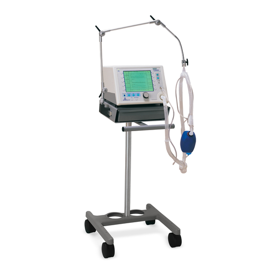
BiPAP Vision (Figure 1-1) user interface includes multi-function keys, real time graphic displays, and integral patient and system alarms. Figure 1-1: BiPAP Vision The BiPAP Vision features a centrifugal blower to generate airflow and internal oxygen module, allowing single or combined gas therapy. The system operates in these modes: •... -
Page 10: Service Notice
1.1 Service Notice Read this manual thoroughly prior to performing service or maintenance on the BiPAP Vision. This manual contains advanced troubleshooting, calibration, and maintenance instructions. All maintenance and repair work should be performed by qualified biomedical technicians who have received appropriate training and authorization to provide maintenance, repair, and service for the BiPAP Vision. - Page 11 • Tee fitting, 1/8 in. OD • Test cable (P/N 582161) • Test cable for s/n 106000 and above (P/N 1004823) • Test orifice, 0.25 in.(P/N 332353) • Whisper Swivel II assembly (P/N 332113) 1062788 BiPAP Vision Service Manual © Respironics, Inc.
- Page 12 • P/Ns 1004823 and P/N 1004699 (ribbon cable) (upgraded, new PC/MC boards installed) BiPAP Vision s/n 106000 and higher: • P/N 1004823 NOTE: These test cables are included in BiPAP Vision service kit P/N 1021276. Pressure tubing, 1/8-in. ID Local supplier • 6 in.
-
Page 13: Technical Support
Chapter 1 Introduction and Intended Use 1.3 Technical Respironics is committed to customer satisfaction. Contact Respironics with questions or for technical support: Support U.S. and Canada: Phone: 1-800-345-6443 Fax: 1-800-866-0245 International: Phone: 1-724-387-4000 Fax: 1-724-387-5012 E-Mail: service@respironics.com For Customer Service and Product Support contact: Online: http://www.respironics.com... - Page 14 Chapter 1 Introduction and Intended Use (This page is intentionally blank.) BiPAP Vision Service Manual © Respironics, Inc. 1062788...
-
Page 15: Warnings, Cautions, And Notes
NOTE: Important information concerning the device. 2.1 Warnings • Do not use the BiPAP Vision in the presence of a flammable anesthetic mixture with air, oxygen, or nitrous oxide. • Oxygen supports combustion. Do not use oxygen while smoking or in the presence of an open flame. -
Page 16: Cautions
Do not allow any liquid to enter the cabinet or the inlet filter during cleaning. • If the BiPAP Vision is exposed to temperatures near the specified limits for operating, storage, or transport temperatures, allow the device to acclimate to room temperature before use. -
Page 17: Theory Of Operation
The PC board transmits process data to the main control (MC) board, which then provides overall control of the BiPAP Vision and sends instructions to the PC board regarding required ILFR-PRV valve stem positions and blower speed. - Page 18 Table 3-1: BiPAP Vision Subsystems Subsystem Function Power supply subsystem Provides the bulk supply DC voltage to the BiPAP Vision subsystems. (PSS) Main control (MC) board Performs all control, data acquisition, and calculations required for user-selected parameters. The MC board also performs the start-up test and reports all errors.
- Page 19 Chapter 3 Theory of Operation Figure 3-1 shows the BiPAP Vision block diagram. Filter enclosure Blower muffler Blower ILFR valve PRV valve baffle AFM flow body Applies to units with s/n 106000 and above Oxygen baffle installed in newer (s/n 106000 and above) and upgraded units...
- Page 20 Chapter 3 Theory of Operation (This page is intentionally blank.) BiPAP Vision Service Manual © Respironics, Inc. 1062788...
- Page 21 Chapter 3 Theory of Operation Figure 3-2 shows the BiPAP Vision pneumatic block diagram. Ambient Proportional Oxygen Valve Oxygen Oxygen Regulator Oxygen Flow Sensor Pressure Oxygen Module 50-100 PSI Oxygen Inlet To PC Board J6 To PC Board J8 To PC Board J7...
- Page 22 Chapter 3 Theory of Operation (This page is intentionally blank.) BiPAP Vision Service Manual © Respironics, Inc. 1062788...
-
Page 23: Pss Board
PSS board still includes the J4 header. Figure 3-3: PSS Block Diagram 3.1.1 Input Range The BiPAP Vision can operate with an input of 100, 120, 230, or 240 VAC (±10%) depending on the model. 3.1.2 DC Supply The output DC supply is fused at 30 amps (A) and delivers between 20.6 VDC... -
Page 24: Overvoltage Disconnect
On / Off switch (state of switch high-low signal sent through J2 pin 6 to the MC board). • Circulation fan current sense information (hard-wired at J8) connects to (J12) on the PC board. BiPAP Vision Service Manual © Respironics, Inc. 1062788... -
Page 25: Mc Board
NOTE: is generally abbreviated as the MC board. When non-upgraded units (built referring specifically to older boards in s/n 105999 and below), it is called the main control subsystem (MCS) board. 1062788 BiPAP Vision Service Manual © Respironics, Inc. -
Page 26: Power Circuitry
If that voltage drops below a reference signal, the comparator output goes low. A resistor provides hysteresis on the comparator, and a signal is sent to the microcontroller to indicate that battery backup voltage is functional. 3-10 BiPAP Vision Service Manual © Respironics, Inc. 1062788... -
Page 27: Watchdog And Power On Reset Circuit
ICB interface: a PAL provides the logic that controls the ICB interface • Serial interface: +5 V logic voltage is converted into +10-V RS-232 voltages through transmit (TXD) and receive (RXD) lines. 3-11 1062788 BiPAP Vision Service Manual © Respironics, Inc. -
Page 28: Pc Board
NOTE: is generally abbreviated as the PC board. older boards in non-upgraded units When referring specifically to (built s/n 105999 and below), it is called the pressure airway subsystem (PAS) board. 3-12 BiPAP Vision Service Manual © Respironics, Inc. 1062788... -
Page 29: Microcontroller Interface
PC functions and system errors (J3 on PAS boards built s/n 105999 and below, unless upgraded; for units built s/n 106000 and above, the RS-232 connector is on the rear of the unit). 3-13 1062788 BiPAP Vision Service Manual © Respironics, Inc. -
Page 30: Dc Board
NOTE: is generally abbreviated as the DC board. non-upgraded units (built When referring specifically to older boards in s/n 105999 and below), it is called the display control subsystem (DCS) board. 3-14 BiPAP Vision Service Manual © Respironics, Inc. 1062788... -
Page 31: Dc/Dc Converter
Chapter 4 describes how to recharge the battery. 3.4.9 Check Vent LED Enable Current Check An internal test verifies that the Check Vent LED current is acceptable. 3-15 1062788 BiPAP Vision Service Manual © Respironics, Inc. -
Page 32: Vent Inop Led Current Check
MC board. An audible alarm also occurs when an incorrect key is pressed, an adjustable parameter has reached its limit, or the error signal has been activated. 3-16 BiPAP Vision Service Manual © Respironics, Inc. 1062788... -
Page 33: Audible Alarm Current Check
This function resets the processor if the software stops functioning correctly. When a low logic level is detected, the ELC is activated and the system shuts down. 3-17 1062788 BiPAP Vision Service Manual © Respironics, Inc. -
Page 34: Airflow Module (Afm)
AFM circuit board. Air flow to patient Temperature sensor Flow body Flow sensor board Pressure sensor EEPROM Power supply Air flow from valves Figure 3-7: AFM Block Diagram 3-18 BiPAP Vision Service Manual © Respironics, Inc. 1062788... -
Page 35: Flow Body
An extra line pulls a PC microcontroller line near 0 V. Line voltage above 2 V indicates that the AFM is not connected, and the PC board enters the error state. 3-19 1062788 BiPAP Vision Service Manual © Respironics, Inc. -
Page 36: Oxygen Module (Om)
OM. To AFM input Flow Flow sensor body Power supply board EEPROM Manifold/ Valve control regulator Oxygen inlet Figure 3-8: OM Block Diagram 3-20 BiPAP Vision Service Manual © Respironics, Inc. 1062788... -
Page 37: Ventilator Modes
For example (Figure 3-9), if the Rate setting is 10 breaths per minute (BPM), the total respiratory cycle is 6 seconds. If a spontaneous trigger occurs before the inspiratory cycle is complete, the BiPAP Vision delivers a spontaneous 3-21 1062788... -
Page 38: Proportional Assist Ventilation / Timed Mode (Pav/T)
3.7.3 Proportional Assist Ventilation / Timed Mode (PAV/T) PAV/T incorporates some features of S/T mode and is a software enhancement only. The appropriate BiPAP Vision Clinical Manual describes PAV/T in detail. 3-22 BiPAP Vision Service Manual © Respironics, Inc. 1062788... -
Page 39: Nurse Call/Remote Alarm (S/N 106000 And Above Only)
106001 - 106368. Central alarm system, 1, 2 1, 2 Open contacts = no alarm. Default factory normally open output configuration for s/n 106369 and above. 3-23 1062788 BiPAP Vision Service Manual © Respironics, Inc. - Page 40 Theory of Operation Figure 3-10: MC Board Jumper Locations CAUTION: The BiPAP Vision nurse call/remote alarm port must be connected to nurse call systems that meet relevant local safety standards. The nurse call port must be connected to a low voltage circuit (<...
-
Page 41: Periodic Maintenance
CAUTION: Do not immerse the device in water or allow any liquid to enter the enclosure or inlet filter. These instructions are for the BiPAP Vision ventilator only. To clean accessories, see the applicable instructions. 1062788 BiPAP Vision Service Manual © Respironics, Inc. - Page 42 Use only Respironics-approved parts. Nylon mesh inlet filter Air inlet filter housing Air inlet filter cover Air inlet filter element (white side faces out) Figure 4-1: Replacing the Inlet Filter BiPAP Vision Service Manual © Respironics, Inc. 1062788...
-
Page 43: Nylon Mesh Inlet Filter
Inlet filter inlet filter Air inlet filter element housing element housing Air inlet filter cover Screws Air inlet filter (x2) cover Nylon mesh inlet filter Figure 4-2: Replacing the Nylon Mesh Inlet Filter 1062788 BiPAP Vision Service Manual © Respironics, Inc. -
Page 44: Oxygen Regulator Filter
Oxygen module s/n here Oxygen module regulator bowl (P/N 582154) Oxygen module regulator filter (P/N 1007547) Figure 4-3: Removing the Oxygen Regulator Bowl and Filter (OM s/n 299999 and below) BiPAP Vision Service Manual © Respironics, Inc. 1062788... - Page 45 Oxygen module regulator bowl (P/N 1007546) Oxygen module regulator filter (P/N 1007547) Oxygen inlet spring (P/N 1030632) Figure 4-4: Removing the Oxygen Regulator Filter and Bowl (OM s/n 300000 and above) 1062788 BiPAP Vision Service Manual © Respironics, Inc.
-
Page 46: Fuses
4.0 A circulation fan muffler (P/N 1041193). Ventilator s/n • Use P/N 582100 (115 VAC) 100499 and below • Use P/N 1000750 (220 and 240 VAC) Gently pry fuse door here Figure 4-5: Opening the Fuse Door BiPAP Vision Service Manual © Respironics, Inc. 1062788... - Page 47 Chapter 4 Periodic Maintenance Power entry module Fuse drawer Fuse (note arrow) Figure 4-6: Replacing the Fuses 1062788 BiPAP Vision Service Manual © Respironics, Inc.
-
Page 48: Internal Alarm Battery
CAUTION: Prolonged storage of the BiPAP Vision at high temperatures, above 80 ºF (27 ºC) can result in premature battery failure. Failure to recharge a battery when in storage for long periods reduces battery life, activates the Check Vent alarm, and generates error code 205. - Page 49 3. During the normal charge, the ventilator can remain in the Exhalation Port/Language screen, in Standby mode, or in Diagnostic mode. Press Alarm reset to silence audible alarms. 4. If the fast charge is successful, the battery is fully recharged after 24 hours. 1062788 BiPAP Vision Service Manual © Respironics, Inc.
-
Page 50: Verifying The Charge
2. Wait 2 minutes to determine if the Check Vent alarm activates and an error code 205 is displayed in the Error Message screen. If not, then the unit is ready for use. 4-10 BiPAP Vision Service Manual © Respironics, Inc. 1062788... -
Page 51: Periodic Maintenance Log
Blower: perform blower valve calibra- tion. BiPAP Vision ventilator: • Clean exterior. • Vacuum dust/lint from interior. • Complete system final test. Record hours of operation (displayed on Options screen) Tested by: ________________________________ Date: _______________ 4-11 1062788 BiPAP Vision Service Manual © Respironics, Inc. - Page 52 Chapter 4 Periodic Maintenance (This page is intentionally blank.) 4-12 BiPAP Vision Service Manual © Respironics, Inc. 1062788...
-
Page 53: Component Removal/Installation
Electrical shock hazard. Disconnect the electrical supply before attempting any repairs. CAUTION: Electronic components used in this device are subject to damage from static electricity. Perform all repairs in an antistatic, ESD-protected environment. 1062788 BiPAP Vision Service Manual © Respironics, Inc. -
Page 54: Major Components
Chapter 5 Component Removal/Installation 5.1 Major Figure 5-1 shows an exploded view of the BiPAP Vision ventilator, and Figure 5-2 shows an exploded view of the front panel assembly. Components Top enclosure Filter enclosure assembly Transformer Inlet filter Filter enclosure... - Page 55 Chapter 5 Component Removal/Installation Display control (DC) board Mounting plate Liquid crystal display (LCD) Rotary encoder Front panel enclosure Touch pad Rotary encoder knob Figure 5-2: BiPAP Vision Front Panel Assembly Exploded View 1062788 BiPAP Vision Service Manual © Respironics, Inc.
-
Page 56: Air Inlet Filter Element
Use only Respironics-approved filters. Air inlet filter housing Air inlet Nylon mesh filter cover inlet filter Latch Air inlet filter element (white side faces out) Figure 5-3: Replacing the Air Inlet Filter Element BiPAP Vision Service Manual © Respironics, Inc. 1062788... -
Page 57: Cleaning/Replacing The Nylon Mesh Inlet Filter
NOTE: The nylon mesh inlet filter can be cleaned and reused or replaced, depending on its condition. Use only Respironics-approved filters. 6. If cleaning the filter: use a solution of mild soap and water to clean, then rinse thoroughly. Ensure that the filter is completely dry before reinstalling. -
Page 58: Oxygen Regulator Filter And Bowl
Figure 5-5: Removing the Oxygen Regulator Bowl and Filter (OM s/n 299999 and below) 4. Rotate the oxygen regulator filter counterclockwise to remove it. 5. Install a new oxygen regulator filter, then rotate clockwise to tighten. BiPAP Vision Service Manual © Respironics, Inc. 1062788... - Page 59 Oxygen module regulator bowl (P/N 1007546) Oxygen module regulator filter (P/N 1007547) Oxygen inlet spring (P/N 1030632) Figure 5-6: Removing the Oxygen Regulator Filter and Bowl (OM s/n 300000 and above) 1062788 BiPAP Vision Service Manual © Respironics, Inc.
-
Page 60: Fuses
2. Gently pry open the top of the fuse holder door. The door hinges downward. Gently pry fuse door here Figure 5-7: Opening the Fuse Door BiPAP Vision Service Manual © Respironics, Inc. 1062788... -
Page 61: Voltage Selection
1. Turn the ventilator off and disconnect the power cord from the back of the device and the wall outlet. 2. Gently pry open the top of the fuse holder door. The door hinges downward. 1062788 BiPAP Vision Service Manual © Respironics, Inc. - Page 62 3. Remove the drum from the power entry module, and reinsert so that the selected voltage is visible. Insert drum so that selected voltage is visible Figure 5-9: Selecting the Voltage 5-10 BiPAP Vision Service Manual © Respironics, Inc. 1062788...
-
Page 63: Top Enclosure
4. Pull the enclosure back to disengage the latch that attaches the top enclosure to the bottom enclosure, then lift the top enclosure away from the device. Top enclosure Screw (x2) Bottom enclosure Figure 5-10: Removing the Top Enclosure 5-11 1062788 BiPAP Vision Service Manual © Respironics, Inc. -
Page 64: Front Panel Enclosure
Intermodule communications bus (ICB) cable (ribbon cable) • Alarm cable (DC J12) CAUTION: To avoid damaging the front panel or bottom enclosures, do not tilt the front panel beyond 45 degrees while attached to the bottom enclosure. 5-12 BiPAP Vision Service Manual © Respironics, Inc. 1062788... -
Page 65: Display Control (Dc) Board
6. Lift the front panel slightly to remove it from the tabs on the bottom enclosure. 7. Set the front panel enclosure face down and remove the screw that attaches the ground wire and shielding foil to the DC board. 5-13 1062788 BiPAP Vision Service Manual © Respironics, Inc. - Page 66 DC board cable (DC J2) Rotary encoder cable (DC J10) Touch pad ribbon cable (DC J6) LCD ribbon cable (DC J9, mounting plate side) Mounting plate Figure 5-13: Removing the Board 5-14 BiPAP Vision Service Manual © Respironics, Inc. 1062788...
-
Page 67: Rotary Encoder
6. From the front of the enclosure, install the washer and nut onto the shaft and tighten the nut. 7. Reinstall the knob onto the shaft. 8. Reinstall the rotary encoder cable to DC J10. 5-15 1062788 BiPAP Vision Service Manual © Respironics, Inc. -
Page 68: Touch Pad
If the touch pad is adhered out of position, use a small amount of isopropyl alcohol to remove the touch pad, allow it to dry, and then re-align the touch pad with the front panel. 5-16 BiPAP Vision Service Manual © Respironics, Inc. 1062788... - Page 69 6 mounting screws. 10. Reinstall the rotary encoder knob to its shaft. 11. Insert the touch pad ribbon cable completely into DC J6. 5-17 1062788 BiPAP Vision Service Manual © Respironics, Inc.
-
Page 70: Lcd Assembly
Rotary encoder cable (DC J10) Figure 5-16: Removing the Mounting Plate 4. Tilt the mounting plate back, and remove the four screws that attach the LCD to the mounting plate. 5-18 BiPAP Vision Service Manual © Respironics, Inc. 1062788... - Page 71 LCD wires. LCD assembly Mounting plate 4-40 x 3/8 screw (x4) (6 lbf-in.) Cable feeds through cutout in mounting plate Figure 5-17: Removing the LCD Assembly 5-19 1062788 BiPAP Vision Service Manual © Respironics, Inc.
-
Page 72: Blower
5. Disconnect the blower motor cable from the PC board (PC J5). 6. Lift the blower up and then pull to remove from the silicone coupling. NOTE: If necessary, use isopropyl alcohol to lubricate the muffler grommet when reinstalling the muffler. 5-20 BiPAP Vision Service Manual © Respironics, Inc. 1062788... -
Page 73: Oxygen Module (Om) Assembly
Figure 5-19: Removing the Oxygen Cover 3. Remove the ribbon cable from the OM flow sensor (ribbon cable connects to PC J6). 4. Pull the hose from the flow sensor outlet. 5-21 1062788 BiPAP Vision Service Manual © Respironics, Inc. - Page 74 6. From the back panel, loosen (but do not remove) the two upper screws on the oxygen manifold. Remove the lower screw completely from the manifold. 7. Lift the OM from the bottom enclosure. Oxygen cover Ground wire Figure 5-21: The OM 5-22 BiPAP Vision Service Manual © Respironics, Inc. 1062788...
-
Page 75: Air Flow Module (Afm), Oxygen Baffle
6. Pull to remove the oxygen baffle from the AFM inlet. NOTE: The oxygen baffle is standard on units built s/n 106000 and above. Although not standard, the oxygen baffle can be installed in units built s/n 105999 and below. 5-23 1062788 BiPAP Vision Service Manual © Respironics, Inc. -
Page 76: Pressure Relief Valve (Prv)
4. Gently lift up and away from the inline flow restrictor (ILFR) valve. ILFR valve Bottom enclosure 6-32 locknut (x2) PRV cable (6 lbf-in.) (connects to PC J7) Figure 5-23: Removing the PRV 5-24 BiPAP Vision Service Manual © Respironics, Inc. 1062788... -
Page 77: Inline Flow Restrictor (Ilfr) Valve
5. Gently lift up and away from the blower. 6-32 x 1/4 screw (x1) (10 lbf-in.) Outside back panel ILFR valve Bracket Connection to ILFR cable blower (PC J8) Silicone coupling Figure 5-24: Removing the ILFR Valve 5-25 1062788 BiPAP Vision Service Manual © Respironics, Inc. -
Page 78: Main Power Switch
3. Pull the switch away from the back panel, feeding its cable through the back panel cutout. Back panel Main power switch Main power switch cable (PSS J7) Power supply subsystem (PSS) Bottom enclosure Figure 5-25: Removing the Main Power Switch 5-26 BiPAP Vision Service Manual © Respironics, Inc. 1062788... -
Page 79: Fan
Fan cable (from lower left) to PSS J6 Standoff (x4) (6 lbf-in.) 6-32 x 3/8 screw (x4) Fan outlet cover (6 lbf-in.) Route fan cable over capacitor Figure 5-26: Removing the Fan 5-27 1062788 BiPAP Vision Service Manual © Respironics, Inc. -
Page 80: Pressure Control (Pc) Board
6. Release the tabs on the 7 nylon standoffs that retain the PC board. 7. Lift the PC board away from the bottom enclosure. 5-28 BiPAP Vision Service Manual © Respironics, Inc. 1062788... - Page 81 PSS voltage monitoring cable PSS cable OM cable AFM tubing Proximal pressure tubing Standoff (x7) ICB cable Proximal pressure tubing to MT1 AFM tubing to MT3 Figure 5-27: The PC Board 5-29 1062788 BiPAP Vision Service Manual © Respironics, Inc.
-
Page 82: Main Control (Mc) Board
(x3) (2 lbf-in.) MC board RS-232 to DC cable Screw (x2) (MC J6 to DC J5) Stainless steel standoff (x1) Bottom (2 lbf-in.) enclosure Figure 5-28: Removing the MC Board 5-30 BiPAP Vision Service Manual © Respironics, Inc. 1062788... -
Page 83: Alarm
3. Remove the 2 screws that attach the alarm to the bottom enclosure. 4. Lift the alarm from the bottom enclosure. Bottom enclosure 6-32 x 1/4 screw (x2) (2 lbf-in.) Alarm Alarm cable connects to DC J12 Figure 5-29: Removing the Alarm 5-31 1062788 BiPAP Vision Service Manual © Respironics, Inc. -
Page 84: Power Supply Subsystem (Pss)
(4 lbf-in.) Power switch cable (PSS J7) Transformer cable (PSS J1) Fan cable (PSS J6) Power indicator LED cable Voltage monitoring cable (PSSJ8- PC J12) Figure 5-30: Removing the PSS 5-32 BiPAP Vision Service Manual © Respironics, Inc. 1062788... -
Page 85: Connector
Back panel (inside) RS-232 connector (red cable stripe points up) Cable connects to MC J3 Back panel (outside) RS-232 connector M2.5 x 8 screw (x2) Figure 5-31: Removing the RS-232 Connector 5-33 1062788 BiPAP Vision Service Manual © Respironics, Inc. -
Page 86: Nurse Call/Remote Alarm Connector
4. Feed the connector and cable through the cutout in the back panel. Nut (x1) (10 lbf-in.) Back panel (inside) Nurse call/remote alarm connector Cable connects to MC J5 Back panel (outside) Figure 5-32: Removing the Nurse Call/Remote Alarm Connector 5-34 BiPAP Vision Service Manual © Respironics, Inc. 1062788... -
Page 87: Ac Inlet Assembly
4-40 locknut (x2) (6 lbf-in.) AC inlet Ground wires (from AC inlet and PSS) 8-32 nut (x1 per ground wire) #8 washer (x1) (10 lbf-in.) Figure 5-33: Removing the AC Inlet Assembly 5-35 1062788 BiPAP Vision Service Manual © Respironics, Inc. -
Page 88: Transformer
3. Disconnect the transformer cables from the PSS J1 and AC inlet assembly. Transformer cable to AC inle Transformer cable Transformer connection cable to PSS J1 Transformer 1/4-20 nut (x1) (20 lbf-in.) Plate Figure 5-34: Removing the Transformer 5-36 BiPAP Vision Service Manual © Respironics, Inc. 1062788... -
Page 89: Pressure Relief Valve (Prv) Enclosure
1. From the underside of the bottom enclosure, remove the four screws that attach the PRV enclosure. 2. Remove the PRV enclosure. 6-32 x 1/4 screw (x4) (10 lbf-in.) PRV enclosure Bottom enclosure Figure 5-35: Removing the PRV Enclosure 5-37 1062788 BiPAP Vision Service Manual © Respironics, Inc. -
Page 90: Back Panel Strain Relief
1. Remove the screw that attaches the back panel strain relief. 2. Remove the strain relief. 6-32 x 1/4 screw (x1) (2 lbf-in.) Strain relief Figure 5-36: Back Panel Strain Relief 5-38 BiPAP Vision Service Manual © Respironics, Inc. 1062788... -
Page 91: Bumper Feet
To avoid contacting the power supply, do not over-tighten the left rear bumper foot. NOTE: When installing the ventilator to the universal cart, replace the rear bumper foot with the cart’s captive hardware. 5-39 1062788 BiPAP Vision Service Manual © Respironics, Inc. - Page 92 Chapter 5 Component Removal/Installation (This page is intentionally blank.) 5-40 BiPAP Vision Service Manual © Respironics, Inc. 1062788...
-
Page 93: Troubleshooting
• Section 6.7 describes how to perform service if the ventilator continues operating when both a Vent Inop and a Check Vent (error code 201) occur. 1062788 BiPAP Vision Service Manual © Respironics, Inc. -
Page 94: Troubleshooting Common Problems
10 operation. the Exhalation Port Test seconds or longer, for software 2.Check power source and power cord screen. versions 11.0 - 11.11, 12.0 - connections. 12.7, and 13.0 - 13.7. BiPAP Vision Service Manual © Respironics, Inc. 1062788... - Page 95 Chapter 6 Troubleshooting Table 6-1: Troubleshooting Common Problems Symptom Possible cause Corrective action Check Vent icon lights, See Section 6.4. audible alarm sounds Vent Inop icon lights, audible See Section 6.5. alarm sounds 1062788 BiPAP Vision Service Manual © Respironics, Inc.
-
Page 96: Alarm Indicators
Chapter 6 Troubleshooting 6.2 Alarm Indicators The BiPAP Vision checks its function at startup and periodically during operation. Ventilator microprocessors continuously monitor internal sensor readings and evaluate operation. The ventilator analyzes and reports any discrepancies according to the level of severity. -
Page 97: Patient Alarm Indicators
If an alarm condition is corrected, the audible alarm turns off. The only way to clear a visual patient alarm indicator is to press the Alarm reset key. If the alarm condition is not corrected, the audible and visual alarm indicators immediately turn on. 1062788 BiPAP Vision Service Manual © Respironics, Inc. -
Page 98: Flow Limit Control (Flc) State
160-170 LPM, the flow limit algorithm decreases the pressure to reduce the flow to 160-170 LPM. For software versions 13.2 and later, FLC terminates immediately pressure drops to 4 cmH O and the flow is above 160-170 LPM. BiPAP Vision Service Manual © Respironics, Inc. 1062788... - Page 99 (that is, the audible alarm is silenced but the visual alarm remains). To clear the alarm, press the Alarm reset key. NOTE: During FLC oxygen concentration is 21%, regardless of the setting. 1062788 BiPAP Vision Service Manual © Respironics, Inc.
-
Page 100: Alarm Troubleshooting
• High pressure alarm limit. 0.5 s. Ventilator terminates limit set below inspiration. Cancels if pressure setting. pressure during a subsequent breath is below the high pressure limit. BiPAP Vision Service Manual © Respironics, Inc. 1062788... - Page 101 • Insufficient or 1.Check oxygen supply and Ventilation continues. Alarm disconnected oxygen connections. does not self-cancel. supply. 2.Check oxygen regulator inlet • Blocked oxygen filter and replace if regulator inlet filter. necessary. 1062788 BiPAP Vision Service Manual © Respironics, Inc.
- Page 102 1 cmH O for over 1 s. Cancels if proximal pressure rises above 1 cmH O. Alarm automatically cancelled if ventilator enters flow limit control (FLC) state. 6-10 BiPAP Vision Service Manual © Respironics, Inc. 1062788...
-
Page 103: Troubleshooting Check Vent Error Codes
Perform corrective action for the error code. Verify that problem is corrected. Perform applicable testing and calibration (Chapter 7). Figure 6-2: Check Vent Troubleshooting Flow Chart 6-11 1062788 BiPAP Vision Service Manual © Respironics, Inc. - Page 104 2.Replace PC board. Blower speed exceeds 16500 revolutions per 1.Replace blower. minute (RPM) limit. 2.Replace PC board. Oxygen module (OM) disconnected from PC 1.Replace OM cable. board. 2.Replace OM. 3.Replace PC board. 6-12 BiPAP Vision Service Manual © Respironics, Inc. 1062788...
-
Page 105: Troubleshooting Vent Inop Error Codes
Perform corrective action. Verify that problem is corrected. Replace top enclosure. Perform applicable testing and calibration (Chapter 7). Figure 6-3: Vent Inop Troubleshooting Flow Chart 6-13 1062788 BiPAP Vision Service Manual © Respironics, Inc. - Page 106 MCU detects software interrupt execution. Replace subsystem with lit error LED. E08 (DC) 1608 (PC) 609 (MC) MCU detects unused interrupt execution. Replace subsystem with lit error LED. E09 (DC) 1609 (PC) 6-14 BiPAP Vision Service Manual © Respironics, Inc. 1062788...
- Page 107 Reply timer (Trply) timeout on third send to 1.Replace ICB cable. (MC, DC, PC) DC-MC: slave did not respond within 1 msec of 2.Replace DC board. last byte sent from MC. 3.Replace MC board. 4.Replace PC board. 6-15 1062788 BiPAP Vision Service Manual © Respironics, Inc.
- Page 108 Tack timeout on third send to PC: Tack not 1.Replace ICB cable. N/A (DC) received within 750 usec of last byte sent. 2.Replace PC board. N/A (PC) 3.Replace DC board. 4.Replace MC board. 6-16 BiPAP Vision Service Manual © Respironics, Inc. 1062788...
- Page 109 Replace DC board. calculation for screen pixel to start writing to (off screen). DC queue overflow: no room in display queue Replace DC board. for incoming MC message, background not running often enough. 6-17 1062788 BiPAP Vision Service Manual © Respironics, Inc.
- Page 110 ADC could not return Vref value: ADC voltage Replace MC board. test. Power failure without AC failure: loss of bulk 1.Replace MC board. supply without loss of AC input caused by PSI 2.Replace PSS. trip. 3.Replace PC board. 6-18 BiPAP Vision Service Manual © Respironics, Inc. 1062788...
- Page 111 1.Replace ICB cable. complete processing before 10-msec interrupt, 2.Replace DC board. 3 times in one hour. 3.Replace PC board. 4.Replace MC board. PAV/T security failure: software Contact Respironics technical support. implementation not possible. 6-19 1062788 BiPAP Vision Service Manual © Respironics, Inc.
- Page 112 1207 MC communication error: MC did not request 1.Replace ICB cable. status within 30 seconds of startup. 2.Replace MC board. 3.Replace PC board. 4.Replace DC board. 6-20 BiPAP Vision Service Manual © Respironics, Inc. 1062788...
- Page 113 Replace PC board. test error: signal from MUX <0 mV or >500 mV. 1217 Startup bulk supply voltage reference test Replace PC board. error: signal from MUX <18.4 V or >38.88 V. 6-21 1062788 BiPAP Vision Service Manual © Respironics, Inc.
- Page 114 Replace PC board. pressure sensor or ADC. 1220 Operational IFLR voltage reference error: drive Replace PC board. voltage read from internal ADC >40 MV on the second try, immediately following first try. 6-22 BiPAP Vision Service Manual © Respironics, Inc. 1062788...
- Page 115 1.Replace AFM cable >300 mV. 2.Replace AFM 3.Replace PC board. 1308 MC pressure setpoint message error: value in 1.Replace ICB cable. message >40 cmH 2.Replace MC board. 3.Replace PC board. 4.Replace DC board. 6-23 1062788 BiPAP Vision Service Manual © Respironics, Inc.
- Page 116 Total flow sensor error: sensor reading 1.Replace AFM cable. <-200 L/min or >300 L/min. 2.Replace AFM. 131A Oxygen flow sensor error: sensor reading 1.Replace OM cable. >120 L/min for 2.5 s. 2.Replace OM. 6-24 BiPAP Vision Service Manual © Respironics, Inc. 1062788...
- Page 117 Total flow sensor drift error: excessive total 1.Replace AFM cable. flow sensor drift. 2.Replace AFM. 3.Replace PC board. 1326 Oxygen flow sensor drift error: excessive total 1.Replace OM cable. flow sensor drift. 2.Replace OM. 3.Replace PC board. 6-25 1062788 BiPAP Vision Service Manual © Respironics, Inc.
-
Page 118: Interpreting Error Codes
The error code 70E indicates a timeout, because the MC is not receiving communication from the PC. The error code 0 indicates a hardware failure, because the ventilator is powering down. 6-26 BiPAP Vision Service Manual © Respironics, Inc. 1062788... -
Page 119: Vent Inop, Check Vent Error Code 201, Ventilation Continues
Figure 6-4: Applying Contact Grease to MC Board J1 Connector Pins 4. Reinstall the PC board into the MC board. 5. Perform a run-in cycle and system final test (see Chapter 7) before returning the ventilator to service. 6-27 1062788 BiPAP Vision Service Manual © Respironics, Inc. - Page 120 Chapter 6 Troubleshooting (This page is intentionally blank.) 6-28 BiPAP Vision Service Manual © Respironics, Inc. 1062788...
-
Page 121: Testing And Calibration
Chapter 7. Testing and Calibration This chapter describes how to test and calibrate the BiPAP Vision following service. These procedures include: • Exhalation port test (Section 7.1): characterizes the circuit and leak rate of the exhalation port. Perform at each circuit change. - Page 122 Not required Main power switch PC board PSS board Pressure relief valve (PRV) PRV muffler Rotary encoder Rotary encoder knob Not required Rubber feet Not required Top enclosure Not required Touch pad Transformer BiPAP Vision Service Manual © Respironics, Inc. 1062788...
- Page 123 Table 7-1: Test Requirements Following Part Replacement Blower valve Performance System final Replacement part calibration Run-in cycle verification test Power line filter Audible alarm EPROMs (including PAV/T) Oxygen manifold/regulator Oxygen flow module 1062788 BiPAP Vision Service Manual © Respironics, Inc.
- Page 124 (Figure 7-1), then occlude the outlet. Figure 7-1: Exhalation Port Test Setup 2. Turn the main power switch ON, and wait for the unit to perform the system self test (about 5 to 15 seconds). BiPAP Vision Service Manual © Respironics, Inc. 1062788...
-
Page 125: Exhalation Port Test
1. Check that exhalation port is not blocked. EXHALATION PORT, Repeat test. CHECK CIRUIT, 2. Replace these parts in order: PC board, REPEAT TEST PRV, and ILFR. Repeat test after each replacement. 1062788 BiPAP Vision Service Manual © Respironics, Inc. - Page 126 1. Check that internal and external circuits are EXCESSIVE FLOW, during test. properly sealed. Repeat test. CHECK CIRCUIT, 2. Replace these parts in order: PRV, PC REPEAT TEST board. Repeat test after each replacement. BiPAP Vision Service Manual © Respironics, Inc. 1062788...
-
Page 127: Service Laptop Setup
Testing and Calibration 7.2 Service Laptop This section describes how to set up a service laptop for testing and troubleshooting the BiPAP Vision. The ventilator includes all necessary Setup software to work with a service laptop, and does not require additional software. -
Page 128: Setting Up The Equipment
106000 and above: connect the other end of the test cable (1004823) to the back panel of the ventilator, and the RS-232 serial cable to the appropriate connector on the test cable. 3. Turn on the service laptop. BiPAP Vision Service Manual © Respironics, Inc. 1062788... -
Page 129: Operating System Setup
Settings, then click ASCII Setup. 8. Click Echo typed characters locally > OK > OK to return to the HyperTerminal screen. 9. Select File > Save As, and save this session of HyperTerminal to the desktop. 1062788 BiPAP Vision Service Manual © Respironics, Inc. - Page 130 Vent Inop condition, the current error appears automatically. Check vent error code history (MC connection). Check type of breath triggering (MC connection). NOTE: Enter commands in all capital letters, and no carriage return. 7-10 BiPAP Vision Service Manual © Respironics, Inc. 1062788...
-
Page 131: Transferring Total Operating Hours
MC board as shown in Figure 7-4 or Figure 7-5. (If necessary, see Section 7.2 for more information on laptop setup.) Figure 7-4: Setup for Transferring Total Hours for Non-Upgraded Ventilator (s/n 105999 and below) 7-11 1062788 BiPAP Vision Service Manual © Respironics, Inc. - Page 132 6. At the Operating Time Modify screen, follow the onscreen instructions to enter the recorded value for Total Operating Time. 7. Turn the power switch OFF and remove the service laptop from the ventilator. Reassemble the ventilator or continue testing. 7-12 BiPAP Vision Service Manual © Respironics, Inc. 1062788...
-
Page 133: Blower/Valve Calibration
Chapter 7 Testing and Calibration 7.4 Blower/Valve Calibrating the blower and valves for the BiPAP Vision takes about 10 minutes or less, depending on the installed software version. Perform the blower/valve Calibration calibration as required after replacing certain major components. - Page 134 9. Unless the test cable is required for further testing, return the ventilator to its normal configuration: • Power off and disconnect the power cord. • Unplug the test cable and remove the test orifice. • Reinstall the top enclosure. 7-14 BiPAP Vision Service Manual © Respironics, Inc. 1062788...
-
Page 135: Performance Verification
Power on the ventilator. When the Test exhalation port/language screen appears, remove the AC power cord from the back of the ventilator, and confirm that the Vent Inop indicator (wrench) lights and the audible alarm sounds. 7-15 1062788 BiPAP Vision Service Manual © Respironics, Inc. - Page 136 (If the OM and optional alarms are installed, O Flow, Lo MinVent, Hi Rate, and Lo Rate also appear.) Alarm messages in mode/message area Vent Inop and Check Vent indicators light Figure 7-6: Alarm Test Screen 7-16 BiPAP Vision Service Manual © Respironics, Inc. 1062788...
- Page 137 Disconnect alarm activates after a few seconds. Press Alarm silence. 14. Verify that the Lo P alarm is activated. Occlude the ventilator outlet and press Alarm reset to clear the alarm. 7-17 1062788 BiPAP Vision Service Manual © Respironics, Inc.
- Page 138 Measure and record the normal pole, no earth, no L2 earth leakage current and verify that the measured value is < 1000 uA. 11. Record results on the Performance Verification Form that follows. 7-18 BiPAP Vision Service Manual © Respironics, Inc. 1062788...
- Page 139 Reverse pole, no earth, L2 < 300 uA Reverse pole, no earth, no L2 < 1000 uA Normal pole, no earth, no L2 < 1000 uA Tested by: Date: (Print name) (Signature) 7-19 1062788 BiPAP Vision Service Manual © Respironics, Inc.
-
Page 140: Run-In Cycle
6. If an alarm occurs, see Chapter 6 for troubleshooting information. Repeat the run-in cycle as needed until successful completion. 7-20 BiPAP Vision Service Manual © Respironics, Inc. 1062788... -
Page 141: System Final Test
Alarms test Section 7.7.8 Oxygen module (OM) test Section 7.7.9 PAV/T mode test (if installed) Section 7.7.10 Earth resistance and leakage current Section 7.7.11 Nurse call/remote alarm test (if applicable) Section 7.7.12 7-21 1062788 BiPAP Vision Service Manual © Respironics, Inc. - Page 142 Pressure pick-off port for oxygen port (P/N 312710) • 0.25-in. test orifice (P/N 332353) • Pressure tubing NOTE: Tubing lengths between circuit components can vary. However, the maximum length of the entire circuit should not exceed 72 inches. 7-22 BiPAP Vision Service Manual © Respironics, Inc. 1062788...
-
Page 143: System Final Test Setup
Adjust restrictor valve to create a small amount of circuit leak. 3. Use a tee fitting to connect the manometer, pressure pick-off port, and ventilator pressure port together. 7-23 1062788 BiPAP Vision Service Manual © Respironics, Inc. -
Page 144: Power Indicator And Lcd Controls Test
4. Adjust the flow restrictor to a flow of 0 LPM (+ 0.5 LPM). If there is oscillation, open the flow restrictor slightly until the oscillation stops, then slowly close the valve. 7-24 BiPAP Vision Service Manual © Respironics, Inc. 1062788... -
Page 145: Flow Accuracy Test
Compensated total flow shown on the service laptop display. • Verify that Compensated total flow value is within specification for that flow 3. At 120 LPM, verify that outlet pressure shown on the ventilator is 18.0 to 22.0 cmH 7-25 1062788 BiPAP Vision Service Manual © Respironics, Inc. -
Page 146: Dynamic Pressure Regulation Test
(C) to a setting of 0.04 mL/cmH O if using the TTL mechanical lung. • If using the Ingmar QuickLung, set (C) to 50 mL/cmH O, no springs connected. Figure 7-8: Dynamic Pressure Regulation Test Setup 7-26 BiPAP Vision Service Manual © Respironics, Inc. 1062788... -
Page 147: S/T Mode Performance Test
Press Clear Error Messages. Press Time at P to reset. 6. Press System Info, and record the displayed software version and whether the oxygen module or alarm module is installed. 7-27 1062788 BiPAP Vision Service Manual © Respironics, Inc. -
Page 148: Alarms Test
For software versions 11.2 and above, the Loss of AC Power message flashes in the display area upon startup: this does not mean the test fails. Press Alarm reset to clear. 7. Power off the ventilator. 7-28 BiPAP Vision Service Manual © Respironics, Inc. 1062788... -
Page 149: Oxygen Module (Om) Test
4. Power up the ventilator. 5. Select these settings: IPAP = 20 cmH Timed Insp = 1.0 s EPAP = 4 cmH IPAP Rise Time = 0.05 s Rate = 15 BPM % = 21% 7-29 1062788 BiPAP Vision Service Manual © Respironics, Inc. - Page 150 90 to 109%. 16. Close the oxygen cylinder valve and disconnect the oxygen input line. 17. If this test fails, perform the OM calibration (Section 7.8) and repeat this test. 7-30 BiPAP Vision Service Manual © Respironics, Inc. 1062788...
-
Page 151: Pav/T Mode Test (If Installed)
7. Electrical safety analyzer settings: neutral: open; polarity: normal; leakage current: earth leakage. Measure and record the normal pole, no earth, no L2 earth leakage current and verify that the measured value is < 1000 uA. 7-31 1062788 BiPAP Vision Service Manual © Respironics, Inc. -
Page 152: Nurse Call/Remote Alarm Test (If Applicable)
Remote alarm (option 1) Nurse call, NC (option 2) Nurse call, NO (option 3) NOTE: Before testing, ensure that MC board jumpers are set correctly. Figure 7-10: MC Board Jumpers 7-32 BiPAP Vision Service Manual © Respironics, Inc. 1062788... - Page 153 3. Activate a patient alarm (for example, set Apnea = 20 seconds). 4. When the alarm occurs, repeat the connector measurement and verify that it indicates a closed circuit. 5. Power off the ventilator. 7-33 1062788 BiPAP Vision Service Manual © Respironics, Inc.
- Page 154 Invert, Bar Graph, and Test Alarms function correctly Pass Fail Record displayed error messages, if any: Pass Fail Record MC board error codes, if any: Record PC board error codes, if any: 7-34 BiPAP Vision Service Manual © Respironics, Inc. 1062788...
- Page 155 < 1000 uA Normal pole, no earth, no L2 < 1000 uA Nurse Call/Remote Alarm Test Correct continuity with ventilator off and with active alarm Pass Fail Tested by: Date: (Print name) (Signature) 7-35 1062788 BiPAP Vision Service Manual © Respironics, Inc.
-
Page 156: Oxygen Module (Om) Calibration
3. Power on the ventilator and allow it to complete its system self test. Do not enter Monitoring. 4. Adjust R41 on the OM so that the DMM measures 0.225-0.235 VDC. 5. Reassemble the ventilator. 7-36 BiPAP Vision Service Manual © Respironics, Inc. 1062788... -
Page 157: Options And Upgrades
1. Remove the DC board from the ventilator. It is possible to remove the retaining screws and pull the DC board from the enclosure while leaving the touch pad and LCD connections attached. 1062788 BiPAP Vision Service Manual © Respironics, Inc. - Page 158 To avoid damaging pressure transducers, avoid using excessive pressure to remove tubing. Carefully twist the tubing slightly to break the seal, the continue to rotate the tubing as you lift it away from the transducer. BiPAP Vision Service Manual © Respironics, Inc. 1062788...
- Page 159 PC EPROM Ventilator s/n 106000 and above Figure 8-2: PC Board EPROM Location 7. Carefully install the new PC EPROM, aligning the flat edges of the EPROM and the socket. 1062788 BiPAP Vision Service Manual © Respironics, Inc.
- Page 160 9. Carefully install the new MC EPROM and alarm PAL, aligning the flat edges of the EPROM and the socket. 10. Reassemble the ventilator. 11. Perform the run-in cycle and system final test (described in Chapter 7) before returning the ventilator to use. BiPAP Vision Service Manual © Respironics, Inc. 1062788...
-
Page 161: Oxygen Baffle
OM outlet tubing support bracket (no longer needed) • T connection (no longer needed) • 22-mm coupling at OM outlet (no longer needed) OM tubing Oxygen tubing Tee connection 22-mm support bracket coupling Figure 8-5: Removing OM Components 1062788 BiPAP Vision Service Manual © Respironics, Inc. - Page 162 (x2) Circuit board Figure 8-6: Installing Nylon Washers under AFM Mounting Screws 5. Replace the flow body and fasten the screws (Figure 8-7). Flow body Nylon washers (x2) Figure 8-7: Reassembled AFM BiPAP Vision Service Manual © Respironics, Inc. 1062788...
- Page 163 AFM circuit board to secure the AFM in place (Figure 8- OM tubing Oxygen baffle Inserting the AFM into the oxygen baffle Figure 8-9: Installing the AFM 1062788 BiPAP Vision Service Manual © Respironics, Inc.
-
Page 164: Upgrades
9. Perform the system final test (described in Chapter 7) before returning the ventilator to use. 8.2 Upgrades This section summarizes the upgrade history for BiPAP Vision ventilators. 8.2.1 Serial Number 105999 and Below The following upgrades (Table 8-1) do not include these updated items: •... - Page 165 • ICB cable • PC/MC board spacers • Nut for MC center board spacer • Pressure tubing • Cable clamps • Screw for center cable clamp • MC ground screw • Top cover screws 1062788 BiPAP Vision Service Manual © Respironics, Inc.
-
Page 166: Obsolete Repair Kits
(P/N 1041193) Install when replacing 3.5-A fuses with 4.0-A fuses. EPROM upgrade kit (P/N 582180) EPROM upgrade kit, non-PAV, s/n 105999 and below Fuse, international (P/N 582099) Fuse, international (P/N 1000750) 8-10 BiPAP Vision Service Manual © Respironics, Inc. 1062788... -
Page 167: Pc/Mc/Dc Upgrade Installation
Record the total operating hours to enter onto the ventilator when the upgrade is complete. Required equipment: • Ribbon cable, test (P/N 1004699) • Test cable (P/N 582161) • Test cable (P/N 1004823) 8-11 1062788 BiPAP Vision Service Manual © Respironics, Inc. - Page 168 8-32 x 3/8 screw into the mounting hole surrounded by the ground plane (along the transformer edge). 7. Install new nylon standoffs on the MC board mounting holes (front left and back left), then install another standoff between them. Install 2 8-12 BiPAP Vision Service Manual © Respironics, Inc. 1062788...
- Page 169 Connect the blower connector to the PC board. 18. Reinstall the front enclosure, ensuring that all connections are secure. The patient pressure tubing connects from the front enclosure to the middle pressure sensor port on the right side. 8-13 1062788 BiPAP Vision Service Manual © Respironics, Inc.
- Page 170 20. When testing is complete, remove the test ribbon cable from MC board, and install the top enclosure using the two 6-32 x 1/2 screws provided in the upgrade kit. 8-14 BiPAP Vision Service Manual © Respironics, Inc. 1062788...
-
Page 171: Parts List
Appendix A Parts List Table A-1 lists replacement parts for the BiPAP Vision ventilator. WARNING: To reduce the risk of explosion, replace batteries only with the same or equivalent type recommended by the manufacturer, and dispose of battery according to manufacturer instructions. - Page 172 Caster kit, Universal Roll Stand, non-locking 1048897 Circulation fan kit 582132 (includes fan and 4 standoffs, P/N 581526) Connector, DC 1007206 Cover, inlet filter 1003444 Cover, oxygen 1040859 Display control (DC) board (s/n 106000 and above) 1004709 BiPAP Vision Service Manual © Respironics, Inc. 1062788...
- Page 173 Feet, storage tray, Mobile Stand III 1009745 Filter kit, OM manifold/regulator (OM s/n 299999 and 582153 below) (package of 5) Filter kit, OM manifold/regulator (OM s/n 300000 and 1007547 above) (package of 5) 1062788 BiPAP Vision Service Manual © Respironics, Inc.
- Page 174 582101 Inlet fitting, oxygen, DISS 1014805 Inline flow restrictor (ILFR) assembly 582137 Knob, rotary encoder 582157 Label, BiPAP Auto-Trak Sensitivity 1031502 Label, diagnostic/nurse call (s/n 105999 and below) 1004703 LCD assembly 582139 BiPAP Vision Service Manual © Respironics, Inc. 1062788...
- Page 175 Pole, Mobile Stand II 1001923 Pole, oxygen analyzer, Mobile Stand III 1011515 Post, oxygen analyzer, Universal Roll Stand 1048899 Power cord wrap, Universal Roll Stand 1049636 Power supply subsystem (PSS) board 582145 1062788 BiPAP Vision Service Manual © Respironics, Inc.
- Page 176 Shipper (packaging kit), Universal Roll Stand 1049903 Side rail, Universal Roll Stand 1049678 Spring, oxygen inlet 1030632 Standoff, male/female, 6-32 x 1.75 (package of 4, 581526 included in circulation fan kit P/N 582132) BiPAP Vision Service Manual © Respironics, Inc. 1062788...
- Page 177 This kit is now obsolete. Install P/N 1004714GL. Upgrade kit, PC/MC with PAV (s/n 105999 and below) 1000356GL NOTE: This kit is now obsolete. Install P/N 104707GL. Valve coupler, blower 1003728 Vibration isolator, blower (package of 3) 1003893 1062788 BiPAP Vision Service Manual © Respironics, Inc.
-
Page 178: Replacement Part Photos
Appendix A A.1 Replacement Part This section includes photos of the major components of the BiPAP Vision ventilator. Photos PC board s/n 106000 and above (P/N 1004710G) Pressure transducer MT3 (connect AFM tubing to upper port if there are two (one port shown here) - Page 179 Appendix A This board is obsolete: order Upgrade kit, DC/MC/PC (s/n 105999 and below) Figure A-2: PAS (PCS) Board (Obsolete) 1062788 BiPAP Vision Service Manual © Respironics, Inc.
- Page 180 Power cord clamp (P/N 582138) (P/N 1000751) Oxygen regulator bowl (P/N 582154 OM s/n 299999 and below) (P/N 1007546 OM s/n 300000 and above) Figure A-3: Back Panel Components, s/n 106000 and above A-10 BiPAP Vision Service Manual © Respironics, Inc. 1062788...
- Page 181 Fuses (100-120 VAC, P/N 1000749) (230-240 VAC, P/N 1000750) Figure A-4: Fuses Inlet mesh filter (P/N 1000747) Inlet filter (P/N 582101) Inlet filter cover (P/N 1003444) Figure A-5: Inlet Filter Enclosure A-11 1062788 BiPAP Vision Service Manual © Respironics, Inc.
- Page 182 106000 and above Screws (x4), (P/N 1004703) included Circulation fan muffler (English, 3.5 A rating, P/N 582155) (English, 4.0 A rating, P/N 1041193) (International P/N 1005618) Figure A-6: Circulation Fan Muffler A-12 BiPAP Vision Service Manual © Respironics, Inc. 1062788...
- Page 183 (P/N 582148 LCD backlight voltage Main power indicator connection cable connection DC/LCD mounting plate ICB cable (P/N 1004695) Audible alarm connection Rotary encoder connection Figure A-7: DC Board, s/n 106000 and above A-13 1062788 BiPAP Vision Service Manual © Respironics, Inc.
- Page 184 106000 and above Figure A-8: Component Identification (AFM side) Inlet filter enclosure assembly (P/N 582134) Blower muffler (P/N 582129) Oxygen flow module (P/N 1014433) Blower assembly (P/N 582128) Figure A-9: Component Identification (Blower) A-14 BiPAP Vision Service Manual © Respironics, Inc. 1062788...
- Page 185 Figure A-10: Blower Assembly ICB connector Error LED Main power indicator connector LCD/DC cable DC board Audible alarm battery Touch pad cable Ground connection Rotary encoder Front panel enclosure Figure A-11: Front Panel Assembly A-15 1062788 BiPAP Vision Service Manual © Respironics, Inc.
- Page 186 Appendix A DC board DC EPROM DC/LCD cable (P/N 1016457) Touch pad ribbon cable Rotary encoder (P/N 582148) Figure A-12: DC Cable Connections A-16 BiPAP Vision Service Manual © Respironics, Inc. 1062788...
- Page 187 DC EPROM DC board (P/N 1004709) (DC board back view) Audible alarm battery Audible alarm connection Touch pad Rotary Power supply ICB connector connector encoder connection connection Figure A-13: DC Board A-17 1062788 BiPAP Vision Service Manual © Respironics, Inc.
- Page 188 (P/N 582145) AC inlet to transformer AC inlet connection Circulation fan (P/N 582138) (P/N 582132) Transformer assembly RFI filter (part (P/N 582152) of AC inlet) Figure A-14: Component Identification (Inside Back Panel) A-18 BiPAP Vision Service Manual © Respironics, Inc. 1062788...
- Page 189 Figure A-15: Component Identification (PSS) ICB cable, s/n 106000 and above (P/N 1004695) RS-232 cable, s/n 106000 and above (P/N 1004698) Power harness, PC/DC, s/n 106000 and above (P/N 1004695) Figure A-16: DC Cables A-19 1062788 BiPAP Vision Service Manual © Respironics, Inc.
- Page 190 (ILFR) valve (P/N 582137) Pressure regulation valve (PRV) (P/N 582147) AC inlet to transformer thermistor connection OM/PC ribbon cable (part of cable kit P/N 582131) Figure A-17: Component Identification (OM and Pneumatics) A-20 BiPAP Vision Service Manual © Respironics, Inc. 1062788...
- Page 191 OM/PC ribbon cable (part of cable kit P/N 582131) Redundant pressure sensor Audible alarm (P/N 1000743) Error LED ICB cable, s/n 106000 and above (P/N 1004695) Figure A-18: Component Identification (PC Board) A-21 1062788 BiPAP Vision Service Manual © Respironics, Inc.
- Page 192 Oxygen flow module Oxygen regulator/manifold assembly (P/N 1014433) (P/N 1014434) Inlet fitting, DISS (P/N 1014805) Oxygen module (OM) assembly (English P/N 582142) (International P/N 1004977) Figure A-20: Oxygen Module (OM) Assembly A-22 BiPAP Vision Service Manual © Respironics, Inc. 1062788...
- Page 193 Patient pressure sensor Power supply to Circulation fan current DC connector sense connector Power supply Redundant connector pressure sensor AFM connector OM connector ICB connector Error LED EPROM Figure A-21: PC Board A-23 1062788 BiPAP Vision Service Manual © Respironics, Inc.
- Page 194 RS-232 connector MC board battery (P/N 1006005 s/n 106000 and EPROM above) (P/N 1001988 s/n 105999 and below) Error LED Alarm PAL RS-232 to DC (P/N 582158) connection Figure A-22: MC Board A-24 BiPAP Vision Service Manual © Respironics, Inc. 1062788...
- Page 195 Figure A-23: IFLR Valve, PRV, Oxygen Baffle Air flow module (AFM) P/N 582127) Thermistor Flow sensor Pressure sensor Connects to PC board Tubing connects to redundant pressure sensor on PC board Figure A-24: Air Flow Module (AFM) A-25 1062788 BiPAP Vision Service Manual © Respironics, Inc.
- Page 196 (P/N 582145) Main power switch connector Transformer connector Circulation fan power connector Main power LED, connects to front panel Circulation fan current sense cable, connects to PC board Figure A-26: PSS Board A-26 BiPAP Vision Service Manual © Respironics, Inc. 1062788...
- Page 197 Appendix A Inline flow restrictor (ILFR) valve (P/N 582137) Pressure regulation valve (PRV) (P/N 582147) Connect to PC board Figure A-27: Valve Identification (IFLR and PRV) A-27 1062788 BiPAP Vision Service Manual © Respironics, Inc.
- Page 198 Appendix A Transformer assembly (P/N 582152) Connection to PSS Connection to AC inlet Metal retaining plate Top insulation spacer Retaining nut Bottom insulation spacer Figure A-28: Transformer Assembly A-28 BiPAP Vision Service Manual © Respironics, Inc. 1062788...
- Page 199 RS-232 harness, s/n 106000 and above (P/N 1004699) Ground stud Connects to PSS Bottom enclosure (P/N 1004700) Nurse call/remote alarm connection to MC board Connects to PSS Figure A-29: Inside Back Panel A-29 1062788 BiPAP Vision Service Manual © Respironics, Inc.
- Page 200 Appendix A Nurse call/remote alarm cable RS-232 cable MC board Figure A-30: Nurse Call/Remote Alarm Cable Routing A-30 BiPAP Vision Service Manual © Respironics, Inc. 1062788...
- Page 201 Bottom enclosure (English, 3.5 A rating, P/N 582155) s/n 105999 and below (English, 4.0 A rating, P/N 1041193) (P/N 582130) (International P/N 1005618) Figure A-31: Back Panel, s/n 105999 and Below A-31 1062788 BiPAP Vision Service Manual © Respironics, Inc.
- Page 202 DCS board, s/n 105999 and below (obsolete P/N 582133) LCD power connection Main power indicator LED connection Audible alarm connection ICB cable Rotary encoder connection connection Figure A-32: DCS Board, s/n 105999 and Below A-32 BiPAP Vision Service Manual © Respironics, Inc. 1062788...
- Page 203 Rotary encoder connector ICB connector placement for DCS board, s/n 105999 and below upgraded units Power connector (obsolete P/N 582133) Figure A-33: DCS Board in Front Panel Enclosure, s/n 105999 and Below A-33 1062788 BiPAP Vision Service Manual © Respironics, Inc.
- Page 204 Audible alarm connector ICB connector Rotary encoder connector ICB connector placement for upgraded units (part of upgrade kit P/N 1004713 or 1000356) Figure A-34: DCS Board Connectors, s/n 105999 and Below A-34 BiPAP Vision Service Manual © Respironics, Inc. 1062788...
- Page 205 (P/N 1000752) ICB cable, s/n 106000 and above (P/N 1004695) MC board, s/n 106000 and above PC board, (P/N 1004711G) s/n 106000 and above (P/N 1004710G) Figure A-35: Component Identification (Blower) A-35 1062788 BiPAP Vision Service Manual © Respironics, Inc.
- Page 206 EPROM, PAV, s/n 105999 and below (P/N 1003524) ICB cable connector Error LED Note that PCS board is installed in non-upgraded units built s/n 105999 and below Figure A-36: PCS Board A-36 BiPAP Vision Service Manual © Respironics, Inc. 1062788...
- Page 207 Alarm PAL (P/N 582158) ICB cable connection MCS to DCS ground wire EPROM, non-PAV, s/n 105999 and below (P/N 1000286) EPROM, PAV, s/n 105999 and below (P/N 1003524) Figure A-38: MC Board A-37 1062788 BiPAP Vision Service Manual © Respironics, Inc.
- Page 208 Appendix A Front enclosure (P/N 582135) Touch pad, English (P/N 582151) Universal (symbols) (P/N 1004712) Rotary encoder knob German (P/N 582221) (P/N 582157) Figure A-39: BiPAP Vision Front View A-38 BiPAP Vision Service Manual © Respironics, Inc. 1062788...
- Page 209 106000 and above (P/N 1004700) PRV muffler (P/N 582156) Figure A-40: Bottom Enclosure LCD assembly (P/N 582139) LCD backlight (P/N 1014432) Connects to touch pad Connects to DCS board Figure A-41: LCD Assembly A-39 1062788 BiPAP Vision Service Manual © Respironics, Inc.
- Page 210 Appendix A Blower valve coupler (P/N 1003728) Figure A-42: Blower Valve Coupler A-40 BiPAP Vision Service Manual © Respironics, Inc. 1062788...
- Page 211 Test cable for s/n s/n 105999 and below 105999 and below) (P/N 1004699) (P/N 582161) Test cable for s/n 106000 and above and upgraded s/n 105999 and below (P/N 1004823) Figure A-43: Test Cables A-41 1062788 BiPAP Vision Service Manual © Respironics, Inc.
- Page 212 Appendix A (This page is intentionally blank.) A-42 BiPAP Vision Service Manual © Respironics, Inc. 1062788...
-
Page 213: Specifications
220 VAC, 230 VAC and 240 VAC ~ T 1.6 A, 250 V, 5 × 20 mm (all s/n, P/N 1000750) Power consumption 300 VA maximum AC current 3.0 A maximum AC frequency 50/60 Hz 1062788 BiPAP Vision Service Manual © Respironics, Inc. -
Page 214: Pressure
Dynamic regulation + 2 cmH O at sinusoidal flow at + 100 L/min Static regulation + 2 cmH O from -60 to 120 L/min Elevation 0 to 5000 ft. above sea level BiPAP Vision Service Manual © Respironics, Inc. 1062788... -
Page 215: Control Accuracy
Shape trigger, leak flow volume 6 cc or above Spontaneous cycle Spontaneous expiratory threshold (SET), shape cycle, IPAP maximum 3.0 s, flow reversal NOTE: See the BiPAP Vision Clinical Manual for more Auto-Trak details. B.8 Oxygen Module Inlet Pressure range 50 to 100 psig Inlet fitting... -
Page 216: Internal Batteries
Lithium cell, 3 VDC, 300 mAh, non- (original MCS board) rechargeable, P/N 1001988 Located on MCS board Data retention battery Lithium cell, 3 VDC, 300 mAh, non- (current MC board) rechargeable, P/N 1006005 Located on MC board BiPAP Vision Service Manual © Respironics, Inc. 1062788... -
Page 217: Settings
Appendix B B.10 Settings NOTE: See the BiPAP Vision Clinical Manual for PAV/T information. Parameter Range Increments IPAP 4 to 40 cmH 1 cmH EPAP 4 to 20 cmH 1 cmH CPAP 4 to 20 cmH 1 cmH Rate 4 to 40 BPM... -
Page 218: Display Data
Patient leak (P 4 to 120 BPM 1 BPM Peak inspiratory pressure (P 0 to 50 cmH 1 cmH Percent of patient-triggered 0 to 100% breaths (P T. TRIG 0 to 100% BiPAP Vision Service Manual © Respironics, Inc. 1062788... -
Page 219: Schematics
NOTE: These schematics are proprietary and confidential. Do not copy or disclose to third parties beyond the purpose for which they are intended. Patents are pending. 1062788 BiPAP Vision Service Manual © Respironics, Inc. - Page 220 Appendix C Figure C-1: Main Control ( ) Board Microcontroller Interface BiPAP Vision Service Manual © Respironics, Inc. 1062788...
- Page 221 Appendix C Figure C-2: Board Analog Outputs 1062788 BiPAP Vision Service Manual © Respironics, Inc.
- Page 222 Appendix C Figure C-3: Board Watchdog/Real Time Clock BiPAP Vision Service Manual © Respironics, Inc. 1062788...
- Page 223 Appendix C Figure C-4: Board Error Line Control (ELC)/Serial Interface 1062788 BiPAP Vision Service Manual © Respironics, Inc.
- Page 224 Appendix C Figure C-5: Board Power Supply/Status BiPAP Vision Service Manual © Respironics, Inc. 1062788...
- Page 225 Appendix C Figure C-6: Board Bypass Circuitry 1062788 BiPAP Vision Service Manual © Respironics, Inc.
- Page 226 Appendix C Figure C-7: Display Control ( ) Power Conversion Circuitry BiPAP Vision Service Manual © Respironics, Inc. 1062788...
- Page 227 Appendix C Figure C-8: Battery and Indicator Circuitry 1062788 BiPAP Vision Service Manual © Respironics, Inc.
- Page 228 Appendix C Figure C-9: ELC Circuitry C-10 BiPAP Vision Service Manual © Respironics, Inc. 1062788...
- Page 229 Appendix C Figure C-10: Diagnostic Interface and Address Decoding C-11 1062788 BiPAP Vision Service Manual © Respironics, Inc.
- Page 230 Appendix C Figure C-11: User Interface and Safe State Circuitry C-12 BiPAP Vision Service Manual © Respironics, Inc. 1062788...
- Page 231 Appendix C Figure C-12: Microcontroller Interface C-13 1062788 BiPAP Vision Service Manual © Respironics, Inc.
- Page 232 Appendix C Figure C-13: Board Power Conversion Circuitry C-14 BiPAP Vision Service Manual © Respironics, Inc. 1062788...
- Page 233 Appendix C Figure C-14: Board Battery and Indicator Circuitry C-15 1062788 BiPAP Vision Service Manual © Respironics, Inc.
- Page 234 Appendix C Figure C-15: Board ELC Circuitry C-16 BiPAP Vision Service Manual © Respironics, Inc. 1062788...
- Page 235 Appendix C Figure C-16: Board Diagnostic Interface and Address Decoding C-17 1062788 BiPAP Vision Service Manual © Respironics, Inc.
- Page 236 Appendix C Figure C-17: Board Microcontroller Interface C-18 BiPAP Vision Service Manual © Respironics, Inc. 1062788...
- Page 237 Appendix C Figure C-18: Pressure Control ( ) Board CPU C-19 1062788 BiPAP Vision Service Manual © Respironics, Inc.
- Page 238 Appendix C Figure C-19: Board Motor Controller C-20 BiPAP Vision Service Manual © Respironics, Inc. 1062788...
- Page 239 Appendix C Figure C-20: Board Pressure Sensors C-21 1062788 BiPAP Vision Service Manual © Respironics, Inc.
- Page 240 Appendix C Figure C-21: Board Valve Drivers/ELC C-22 BiPAP Vision Service Manual © Respironics, Inc. 1062788...
- Page 241 Appendix C Figure C-22: Board Bypass/Pullup/ICB Databus C-23 1062788 BiPAP Vision Service Manual © Respironics, Inc.
- Page 242 Appendix C Figure C-23: Air Flow Module (AFM) C-24 BiPAP Vision Service Manual © Respironics, Inc. 1062788...
- Page 243 Appendix C Figure C-24: Oxygen Module (OM) C-25 1062788 BiPAP Vision Service Manual © Respironics, Inc.
- Page 244 Appendix C Figure C-25: Power Supply Subsystem (PSS) C-26 BiPAP Vision Service Manual © Respironics, Inc. 1062788...
Need help?
Do you have a question about the BiPAP Vision and is the answer not in the manual?
Questions and answers