Table of Contents
Advertisement
Quick Links
Advertisement
Table of Contents

Related Manuals for Respironics Bipap Harmony S/T


Summary of Contents for Respironics Bipap Harmony S/T
- Page 1 Patient Guide...
- Page 2 1004221 JR 3/15/01...
-
Page 3: Table Of Contents
2 Introduction to the Harmony S/T .............. 7 What is Bi-Level Ventilation? ..........................7 What is the Harmony S/T? ..........................8 Symbols ................................9 How to Contact Respironics ..........................9 3 A Tour of the Harmony S/T ..............10 Overview ................................10 Top Panel ................................. 11 Connecting the Breathing Circuit ........................ - Page 4 4 Using the Harmony S/T ................13 Installing the Inlet Filters ..........................13 Where to Place the Harmony S/T Unit ......................14 Connecting the Breathing Circuit ........................14 Complete Harmony S/T Setup ......................... 16 Plugging the Unit In (Using AC Power) ......................17 Using DC Power ...............................
-
Page 5: Warnings, Cautions, And Notes
• The Harmony S/T ventilator is not intended to provide the total ventilatory requirements of the patient. • Repairs and adjustments must be performed by Respironics-authorized service personnel ONLY. • The prescribed patient settings must be adjusted by Service done by inexperienced, unqualified personnel or trained and authorized personnel only. -
Page 6: Cautions
Cautions A Caution indicates the possibility of damage to the device. • Federal law restricts this device to sale by or on the order of a physician. • Do not expose the Harmony S/T ventilator to tempera- tures at or near the extremes of those shown below. If exposure to such temperatures has occurred, allow the unit to come to room temperature before turning it on. -
Page 7: Intended Use/Indications For Use
If any of the following conditions apply to you, consult your physician before using the Harmony S/T ventilator. The BiPAP Harmony S/T is a non-invasive, pressure Consult your physician if you have: support ventilator used to augment the breathing of patients suffering from acute or chronic respiratory •... -
Page 8: Contents Of The Package
1 Contents of the Package The BiPAP Harmony S/T package contains: • BiPAP Harmony S/T unit • Six feet of tubing • Whisper Swivel II exhalation port Six Feet of • Gray Foam filter Harmony S/T Unit Tubing • Ultra-fine filter Your home care provider should have pre-assembled the tubing, exhalation port, and mask into a breathing circuit. -
Page 9: Introduction To The Harmony S/T
2 Introduction to the Harmony S/T What is Bi-Level Ventilation? The Harmony Ventilator Provides Two Levels of Ventilation. Bi-level ventilation with the Harmony S/T Ventilatory Support System helps you to breathe by supplying two IPAP levels of air pressure. The Harmony S/T provides a higher Pressure pressure—known as IPAP (Inspiratory Positive Airway Pressure)—when you inhale, and a lower pressure—... -
Page 10: What Is The Harmony S/T
What is the Harmony S/T? The Harmony ventilator, shown in Figure 2-2, supplies two levels of air pressure through a breathing circuit. The circuit consists of: • circuit tubing to deliver the air from the ventilator to your interface (e.g., mask) •... -
Page 11: Symbols
AC Power Indicator How to Contact Respironics DC Power Indicator To have your unit serviced, contact your home care Alarms provider. If you need to contact Respironics directly, use the following addresses: System Alarm Indicator Patient Alarm Indicator START STOP... -
Page 12: Tour Of The Harmony S/T
3 A Tour of the Harmony S/T Carrying Handle Overview Figure 3-1 shows the location of the: • controls and indicators Controls/ Indicators • breathing circuit connection • carry handle Breathing Circuit Connection Optional Oxygen Valve Figure 3-1. The Harmony S/T Front and Top. S/T Patient Guide... -
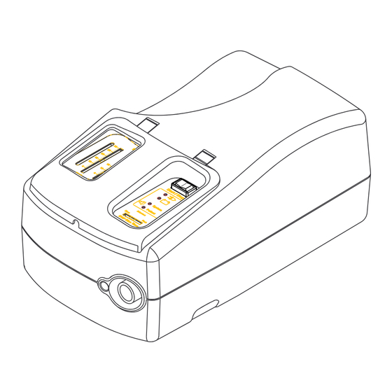
Page 13: Top Panel
Top Panel Start/Stop Switch The top panel contains the controls and indicators you will need when you are using the BiPAP Harmony S/T. Pressure Indicator • Start/Stop switch Power Indicators • AC Power Indicator Alarm • DC Power Indicator Indicators •... -
Page 14: Connecting The Breathing Circuit
Connecting the Breathing Circuit Figure 3-3 shows where the circuit tubing connects to the Harmony S/T unit. Patient Interface Rear Panel Port Figure 3-4 shows the location of the: • air inlet filters • AC inlet • DC inlet Figure 3-3. Breathing Circuit Connection. The Harmony S/T uses a gray pollen filter that is washable and reusable, and a white ultra-fine filter that is disposable. -
Page 15: Using The Harmony S/T
4 Using the Harmony S/T Installing the Inlet Filters The Harmony uses a gray foam filter that is reuseable, and an optional white ultra-fine filter that is disposable. One filter of each kind is supplied with Harmony. Reusable Pollen Filter If your home care provider did not install the inlet filters, you must install at least the gray foam filter before using the Harmony. -
Page 16: Where To Place The Harmony S/T Unit
Where to Place the Harmony S/T Unit Place the Harmony S/T unit on its base somewhere within easy reach of where you will be using it. Make sure that the air inlet on the rear of the unit is not blocked. If you block the air flow around the unit, the unit may not work properly. - Page 17 Connect the exhalation device to the mask Mask or connector. Other Interface ® Attach the Softcap or headgear to the mask— see the instructions that came with your Softcap or headgear. Mask Connector Exhalation Device Step 3 S/T Patient Guide...
-
Page 18: Complete Harmony S/T Setup
Complete Harmony S/T Setup Patient Interface (typical) Figure 4-1 shows the completed breathing circuit setup for the Harmony S/T unit. Exhalation Port Circuit Tubing Figure 4-1. Harmony S/T Complete Breathing Circuit. S/T Patient Guide... -
Page 19: Plugging The Unit In (Using Ac Power)
Plugging the Unit In (Using AC Power) Plug the receptacle end of the AC cord into the AC inlet. Insert the plug end of the AC cord into the wall outlet. WARNING: Never plug the Harmony S/T AC cord into an outlet that is controlled by a wall switch. -
Page 20: Starting The Harmony S/T Unit
Starting the Harmony S/T Unit Relax. Take slow, relaxed breaths through your nose. Press the Start/Stop switch to the START position. The unit will sound two beeps and NOTE: If you are having trouble with your mask, see briefly illuminate all the indicators. This is the Chapter 6 for some suggestions. -
Page 21: Alarms And What To Do
5 Alarms and What to Do Symbol Meaning This chapter describes the Harmony S/T alarms and what Flashing you should do if an alarm is activated. The Harmony S/T unit provides two types of alarms, System Alarm System and Patient. Both types are indicated by visual and audible alarms. - Page 22 WHAT YOU SEE WHAT YOU HEAR WHAT THE UNIT WHY THE ALARM WHAT TO DO DOES SOUNDED Continuous Tone Unit not working Loss of input power Be sure that the AC AC LED Off power cord is plugged DC LED Off into a working outlet System LED On Continuously...
- Page 23 WHAT TO DO WHAT YOU SEE WHAT YOU HEAR WHAT THE UNIT WHY THE ALARM DOES SOUNDED Contact your home Intermittent Beeps Unit not working Internal Failure AC LED On care provider for DC LED On service. System LED On Continuously Patient LED Off Intermittent Beeps...
- Page 24 WHAT TO DO WHAT YOU SEE WHAT YOU HEAR WHAT THE UNIT WHY THE ALARM DOES SOUNDED The external battery is Three beeps every 15 Unit is operating Low external battery AC LED Off about to fail. Seek an seconds DC LED Flashing alternate power source.
-
Page 25: Troubleshooting
6 Troubleshooting This chapter lists problems you could experience with your Harmony unit or mask, and presents possible solutions. PROBLEM WHY IT HAPPENED WHAT TO TRY Inlet filters may be dirty. Clean or replace the inlet air filters as The air out of the mask is much described in Chapter 7. -
Page 26: Mask Discomfort And Corrective Actions
Mask Discomfort and Corrective Actions Problem Why it Happened What to Try Mask feels uncomfortable to wear. 1. Improper Softcap or headgear Check the Softcap or headgear adjustment. adjustment as described in the Softcap or headgear instructions. 2. Improper mask fitting. Contact your home care provider for a refitting or a different size of mask. - Page 27 Problem Why it Happened What to Try Redness occurs when the mask 3. Irritation or allergic reaction to Use a barrier between your skin and ® ® cushion or Comfort Flap mask mask material. the mask, such as 3M’s Microfoam ®...
- Page 28 1. Increase the room humidity. 2. Consult with your doctor or home 2. Improper mask fitting. care provider about using a Respironics humidifier with the ventilator. Nasal, sinus or ear pain Sinus or middle ear infection Stop using the Harmony S/T ventilator and contact your doctor.
-
Page 29: Cleaning The Unit And Filters
7 Cleaning the Unit and Filters Cleaning Your Harmony Unit Before cleaning or performing any routine maintenance, always switch the start/stop switch to disconnect the unit from the power source. NOTE: The following cleaning instructions are for the Harmony unit only. To clean the circuit and accessories, refer to each accessory’s instruction sheet. -
Page 30: Cleaning/Replacing The Inlet Filters
Cleaning/Replacing the Inlet Filters The Harmony unit has two removable filters at the air inlet. The gray foam filter is washable and reusable. The optional white ultra-fine filter is disposable. CAUTION: Dirty inlet filters may cause high operating temperatures and may affect ventilator performance. - Page 31 Step 5 If needed, wash the gray foam filter in warm, soapy water. Rinse the filter thoroughly to remove all soap residue. Allow the filter to completely dry before reinstalling it. Use the extra gray foam filter that was supplied with your Harmony unit while the wet filter dries.
-
Page 32: Using Oxygen With Your Harmony Ventilator
8 Using Oxygen with your Harmony Ventilator If your doctor has prescribed oxygen to be used with your Harmony S/T, follow these instructions to connect oxygen to the breathing circuit. WARNING: If you are using oxygen, your Harmony S/T must be equipped with the optional oxygen valve, shown in Figure 8-1 . - Page 33 Step 1 As shown in Figure 8-2, attach oxygen tubing to the rear oxygen valve port. The oxygen valve prevents oxygen from entering the Harmony S/T enclosure when the unit is stopped. Circuit Step 2 Connect another section of oxygen tubing to From Oxygen Tubing the front valve port, then to the oxygen...
- Page 34 Index AC Indicator 11 DC Indicator 11 AC Inlet 12 DC Inlet 12 Air Inlet Filters 12 Alarms 19 Patient 11 EPAP 7 System 11 EPAP control 11 What to Do 19 Exhalation Port 15 Expiratory Positive Airway Pressure 7 Bi-Level Ventilation 7 Breathing Circuit 8 Filters...
- Page 35 Inspiratory Positive Airway Pressure 7 Pressure Indicator 11 Installing the Inlet Filters 13 Interface 8 Introduction 7 Rear Panel 12 IPAP 7 Respironics IPAP Control 11 How to Contact Us 9 Limited Warranty 35 Start/Stop switch 11 Location 14 Starting the Harmony Unit 18...
- Page 36 Temperatures operating, storage 4 Top Panel Components of 11 Troubleshooting 23 Tubing Breathing Circuit 6, 12, 14 Ventilation, bi-level 7 Warnings 3 Warnings, Cautions, and Notes 3 Warranty 35 S/T Patient Guide...
-
Page 37: Limited Warranty
Respironics, Inc. to the dealer. If the product fails to perform in accordance with the product specifications, Respironics, Inc. will repair or replace – at its option – the defective material or part. Respironics, Inc. will pay customary freight charges from Respironics, Inc. to the dealer location only. This warranty does not cover damage caused by accident, misuse, abuse, alteration, and other defects not related to material or workmanship. - Page 38 S/T Patient Guide...
Need help?
Do you have a question about the Bipap Harmony S/T and is the answer not in the manual?
Questions and answers