Mitsubishi FX3G SERIES User Manual
Hide thumbs
Also See for FX3G SERIES:
- Programming manual (944 pages) ,
- Installation manual (3 pages) ,
- User manual (240 pages)
Table of Contents
Advertisement
Quick Links
Advertisement
Table of Contents
Troubleshooting

Related Manuals for Mitsubishi FX3G SERIES


Summary of Contents for Mitsubishi FX3G SERIES
- Page 1 USER'S MANUAL - Hardware Edition SERIES PROGRAMMABLE CONTROLLERS...
- Page 3 Safety Precautions (Read these precautions before using.) Before installation, operation, maintenance or inspection of this product, thoroughly read through and understand this manual and the associated manuals. Also, take care to handle the module properly and safely. This manual classifies the safety precautions into two categories: Indicates that incorrect handling may cause hazardous conditions, resulting in death or severe injury.
- Page 4 Safety Precautions (Read these precautions before using.) 2. INSTALLATION PRECAUTIONS Reference • Make sure to cut off all phases of the power supply externally before attempting installation or wiring work. Failure to do so may cause electric shock. Reference • Use the product within the generic environment specifications described in Section 4.1 of this manual.
- Page 5 • Do not disassemble or modify the PLC. Doing so may cause fire, equipment failures, or malfunctions. For repair, contact your local Mitsubishi Electric distributor. • Turn off the power to the PLC before connecting or disconnecting any extension cable.
- Page 6 Safety Precautions (Read these precautions before using.) 5. DISPOSAL PRECAUTIONS Reference • Please contact a certified electronic waste disposal company for the environmentally safe recycling and disposal of your device. 6. TRANSPORTATION PRECAUTIONS Reference • When transporting the FX Series PLC incorporating the optional battery, turn on the PLC before shipment, confirm that the battery mode is set using a parameter and the ALM LED is OFF, and check the battery life.
-
Page 7: Safety Precautions
This manual confers no industrial property rights or any rights of any other kind, nor does it confer any patent licenses. Mitsubishi Electric Corporation cannot be held responsible for any problems involving industrial property rights which may occur as a result of using the contents noted in this manual. - Page 8 • Since the examples indicated by this manual, technical bulletin, catalog, etc. are used as a reference, please use it after confirming the function and safety of the equipment and system. Mitsubishi Electric will accept no responsibility for actual use of the product based on these illustrative examples.
-
Page 9: Table Of Contents
Series Programmable Controllers User's Manual - Hardware Edition Table of Contents Table of Contents SAFETY PRECAUTIONS ....................(1) 1. Introduction 1.1 Introduction of Manuals......................... 14 1.1.1 Classification of major components in this manual................ 14 1.1.2 Manual organization and position of this manual ................16 1.1.3 List of manuals .......................... - Page 10 Series Programmable Controllers User's Manual - Hardware Edition Table of Contents 5. Version Information and Peripheral Equipment Connectability 5.1 Version Information ........................44 5.1.1 Version check method ........................44 5.1.2 How to look at manufacturer's serial number ................44 5.1.3 Version upgrade history......................... 44 5.2 Programming Tool Applicability.....................
- Page 11 Series Programmable Controllers User's Manual - Hardware Edition Table of Contents 7.2 Unit Numbers of Special Function Blocks ..................77 7.2.1 Concept of assigning ........................77 7.2.2 Example of assigning ........................77 7.2.3 Application of unit number labels....................78 7.3 Assignment of Communication Channels ..................79 7.3.1 Assignment of communication channels ..................
- Page 12 Series Programmable Controllers User's Manual - Hardware Edition Table of Contents 10. Input Wiring Procedures 10.1 Before Starting Input Wiring ...................... 118 10.1.1 Sink and source input ........................ 118 10.2 24V DC input (Sink and source input type) ................119 10.2.1 Handling of 24V DC input ......................
- Page 13 Series Programmable Controllers User's Manual - Hardware Edition Table of Contents 12.3 External Wiring for Triac (SSR) Output Type ................150 12.3.1 Handling of triac output......................150 12.3.2 External wiring precautions ....................... 151 12.3.3 Example of external wiring ......................152 13.
- Page 14 Series Programmable Controllers User's Manual - Hardware Edition Table of Contents 15.3 FX -32ER-ES/UL, FX -48ER-ES/UL ................... 194 15.3.1 Product specifications........................ 194 15.3.2 External dimensions ........................196 15.3.3 Terminal layout .......................... 196 15.4 FX -32ET-ESS/UL, FX -48ET-ESS/UL ................197 15.4.1 Product specifications........................ 197 15.4.2 External dimensions ........................
- Page 15 Series Programmable Controllers User's Manual - Hardware Edition Table of Contents 16.10 FX -8EYR, FX -16EYR (Relay Output) ................237 16.10.1 Product specifications......................237 16.10.2 Parts identification and terminal arrangement ................. 238 16.10.3 External dimensions ........................ 239 16.11 FX -8EYT, FX -16EYT, FX -16EYT-C (Transistor Output) ..........
- Page 16 Series Programmable Controllers User's Manual - Hardware Edition Table of Contents 18.4 Power Supply ..........................265 18.4.1 FX -20PSU ..........................265 18.5 Connector Conversion Adapter....................265 18.5.1 FX -CNV-ADP ........................265 18.5.2 FX -CNV-BC........................... 266 18.6 Interface Module ........................266 18.6.1 FX-232AWC-H...........................
- Page 17 Series Programmable Controllers User's Manual - Hardware Edition Table of Contents 19.14 Specified Device Monitor Function..................296 19.14.1 System information - specified device monitor function ............296 19.14.2 Differences between specified device monitor screen and monitor/test screen...... 297 19.14.3 Program example1 (when monitoring/testing a timer)............. 297 19.14.4 Program example2 (when monitoring consecutive timers using operation keys)....
- Page 18 Series Programmable Controllers User's Manual - Hardware Edition Table of Contents 20.8 FX-16EYT-TB, FX-16EYT-H-TB ....................329 20.8.1 Specifications ..........................329 20.8.2 Internal circuit ..........................330 20.8.3 Example of output external wiring ..................... 330 20.8.4 External wiring precautions ....................... 331 20.9 FX-16EYS-TB ........................... 332 20.9.1 Specifications ..........................
- Page 19 Series Programmable Controllers User's Manual - Hardware Edition Table of Contents Appendix B: Instruction List Appendix B-1 Basic Instructions ....................368 Appendix B-2 Step Ladder Instructions ..................368 Appendix B-3 Applied Instructions ... in Ascending Order of FNC Number ......369 Warranty..........................
-
Page 20: Introduction
Series Programmable Controllers 1 Introduction User's Manual - Hardware Edition 1.1 Introduction of Manuals Introduction This manual explains the procedures for selecting the system components, main unit specifications and procedures for installing the main unit, specifications for the input/output powered extension units/blocks, and procedures for adding input/output devices, and procedures for operating the display module etc. - Page 21 Series Programmable Controllers 1 Introduction User's Manual - Hardware Edition 1.1 Introduction of Manuals 2) Extension devices (Chapter 15 to Chapter 18) Division Outline Reference Input/output powered extension Chapter 15 This chapter contains explanations for the input/output specifications, external units dimensions and terminal layout for each product.
-
Page 22: Manual Organization And Position Of This Manual
Series Programmable Controllers 1 Introduction User's Manual - Hardware Edition 1.1 Introduction of Manuals 1.1.2 Manual organization and position of this manual This manual describes detail on the hardware, including the system configuration, selection, installation and wiring. The instructions, communication control, analog control and positioning control are explained in separate manuals. -
Page 23: List Of Manuals
Series Programmable Controllers 1 Introduction User's Manual - Hardware Edition 1.1 Introduction of Manuals 1.1.3 List of manuals Series PLC main units supplied only with the hardware manual. For the details of the hardware of FX Series, refer to this manual. For instructions for programming and hardware information on special function devices, refer to the relevant manuals. - Page 24 Series Programmable Controllers 1 Introduction User's Manual - Hardware Edition 1.1 Introduction of Manuals Model name Manual title Manual number Contents code Procedures for handling the RS-485 communication Supplied -485ADP special adapter with JY997D13801 Installation Manual When using, refer also to FX Series User's Manual - product Data Communication Edition.
- Page 25 Series Programmable Controllers 1 Introduction User's Manual - Hardware Edition 1.1 Introduction of Manuals Model name Manual title Manual number Contents code Procedures for handling the 4-ch analog input special Supplied -4AD-ADP adapter with JY997D13901 User's Manual When using, refer also to FX Series product User's Manual - Analog Control Edition.
- Page 26 Series Programmable Controllers 1 Introduction User's Manual - Hardware Edition 1.1 Introduction of Manuals Model name Manual title Manual number Contents code Other manuals When using each product, refer also to the User's Manual - Hardware Edition for the PLC main unit to be installed. Variable analog potentiometers Procedures for handling the 8-ch variable analog Supplied...
-
Page 27: Generic Names And Abbreviations Used In Manuals
Series Programmable Controllers 1 Introduction User's Manual - Hardware Edition 1.2 Generic Names and Abbreviations Used in Manuals Generic Names and Abbreviations Used in Manuals Abbreviation/ Description generic name PLCs Series Generic name for FX Series PLCs Series Generic name for FX Series PLCs Series Generic name for FX... - Page 28 Series Programmable Controllers 1 Introduction User's Manual - Hardware Edition 1.2 Generic Names and Abbreviations Used in Manuals Abbreviation/ Description generic name Handy programming panels Generic name for the following models (HPP) FX-20P, FX-20P-E Generic name for the following models RS-232C/RS-422 converters FX-232AW, FX-232AWC, FX-232AWC-H RS-232C/RS-485 converters...
-
Page 29: Features And Part Names
Series Programmable Controllers 2 Features and Part Names User's Manual - Hardware Edition 2.1 Major Features Features and Part Names Major Features 1. Basic functions the RS-232C expansion board and RS-232C communication special adapter. [Up to 256 input/output points] 2. Input/output high-speed processing The total number of inputs and outputs (128 functions of main unit points maximum) directly connected to the PLC... - Page 30 Series Programmable Controllers 2 Features and Part Names User's Manual - Hardware Edition 2.1 Major Features [Pulse output function] • Computer link → Refer to Data Communication Edition. When output terminals in the transistor output type main unit are used, pulses (open collector •...
-
Page 31: Names And Functions Of Parts
Series Programmable Controllers 2 Features and Part Names User's Manual - Hardware Edition 2.2 Names and Functions of Parts Names and Functions of Parts 2.2.1 Front Panel Factory default configuration (standard) [10] [11] [1] Peripheral device connecting The peripheral device connector, variable analog potentiometers and RUN/STOP switch connector cover are located under this cover. - Page 32 Series Programmable Controllers 2 Features and Part Names User's Manual - Hardware Edition 2.2 Names and Functions of Parts When the top covers are open [10] [1] Peripheral device connecting Connect a programming tool(PC) to program a sequence. → For details on applicable peripheral devices, connector (USB) refer to Chapter 5.
-
Page 33: Sides
MODEL 100-240VAC 50/60Hz 37W OUT:5~30VDC 0.5A SERIAL 8X0001 MITSUBISHI ELECTRIC CORPORATION MADE IN JAPAN Control number Month (Example: Oct.):(1 to 9 = January to September, X = October, Y = November, Z = December) Year (Example: 2008): Last digit of year [3] DIN rail mounting groove The unit can be installed on DIN46277 rail (35 mm (1.38") wide). -
Page 34: Introduction Of Products
Series Programmable Controllers 3 Introduction of Products User's Manual - Hardware Edition 3.1 List of Products and Interpretation of Model Names Introduction of Products List of Products and Interpretation of Model Names The following system configuration is classified into product groups A to N in the product introduction sections given below. -
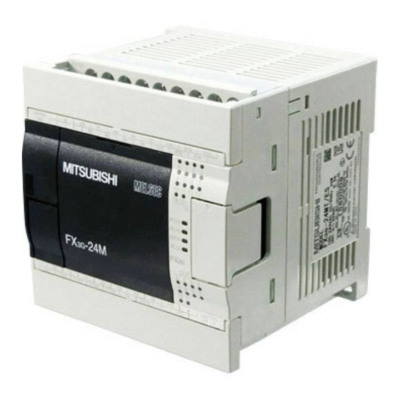
Page 35: Main Units
Series Programmable Controllers 3 Introduction of Products User's Manual - Hardware Edition 3.1 List of Products and Interpretation of Model Names 3.1.1 Main units The main unit incorporates a CPU, memory, input and output terminals and power supply. To establish a system, at least one main unit is necessary. Incorporating power supply, CPU, memory and input/output Series name Power supply, Input/output type: Connection on terminal block... -
Page 36: Input/Output Extension Blocks
Series Programmable Controllers 3 Introduction of Products User's Manual - Hardware Edition 3.1 List of Products and Interpretation of Model Names 3.1.3 Input/output extension blocks The input/output extension block has built-in input or output terminals to add input or output terminals. Connect the input/output extension block to the main unit or input/output powered extension unit. -
Page 37: Special Function Blocks
Series Programmable Controllers 3 Introduction of Products User's Manual - Hardware Edition 3.1 List of Products and Interpretation of Model Names 3.1.4 Special function blocks For details of each product, refer to the product manual. 1) Analog control Analog Model name Description Input Output... -
Page 38: Special Adapters
Series Programmable Controllers 3 Introduction of Products User's Manual - Hardware Edition 3.1 List of Products and Interpretation of Model Names 3.1.8 Special adapters Model name Description -232ADP(-MB) RS-232C communication -485ADP(-MB) RS-485 communication -4AD-ADP 4-ch voltage/current input -4DA-ADP 4-ch voltage/current output -4AD-PT-ADP 4-ch platinum resistance thermometer sensor input (-50 to 250 C) -4AD-PTW-ADP... -
Page 39: Fx Series Terminal Blocks (Cables And Connectors)
Series Programmable Controllers 3 Introduction of Products User's Manual - Hardware Edition 3.1 List of Products and Interpretation of Model Names 3.1.11 FX Series terminal blocks (cables and connectors) 1. FX Series terminal blocks Number of Number of Model name Function input points output points... -
Page 40: Connector Types And Cables For Program Communication
Series Programmable Controllers 3 Introduction of Products User's Manual - Hardware Edition 3.2 Connector Types and Cables for Program Connector Types and Cables for Program Communication RS-232C/RS-422 cable Connection cabling Connection cabling for Peripheral device connector extension devices FX-232AWC-H RS-232C RS-422 Special adapter -232ADP... -
Page 41: Programming Tool
Series Programmable Controllers 3 Introduction of Products User's Manual - Hardware Edition 3.2 Connector Types and Cables for Program 3.2.1 Programming tool The following programming tool supports FX Series PLCs. Model name Description Version 8.72A or later of SW D5C-GPPW-J and SW D5C-GPPW-E supports FX GX Developer Although the tool earlier than version 8.72A can be used for programming by selecting FX (C), restrictions... -
Page 42: Specifications, External Dimensions And Terminal Layout (Main Units)
Series Programmable Controllers 4 Specifications, External Dimensions and Terminal User's Manual - Hardware Edition 4.1 Generic Specifications Specifications, External Dimensions and Terminal Layout (Main Units) This Chapter explains the specifications, external dimensions and terminal layout of the main units. → For the specifications for the input/output powered extension units, refer to Chapter 15. →... -
Page 43: Dielectric Withstand Voltage Test And Insulation Resistance Test
Series Programmable Controllers 4 Specifications, External Dimensions and Terminal User's Manual - Hardware Edition 4.2 Power Supply Specifications 4.1.1 Dielectric withstand voltage test and insulation resistance test Perform dielectric withstand voltage test and insulation resistance test at the following voltage between each terminals and the main unit ground terminal. -
Page 44: Input Specifications
Series Programmable Controllers 4 Specifications, External Dimensions and Terminal User's Manual - Hardware Edition 4.3 Input Specifications Input Specifications The main unit input specifications are explained below. 4.3.1 24V DC Input (sink/source) The input numbers in the table indicate the main unit terminal numbers. "X010 or more" means the numbers from X010 to the largest number that the main unit has. -
Page 45: Output Specifications
Series Programmable Controllers 4 Specifications, External Dimensions and Terminal User's Manual - Hardware Edition 4.4 Output Specifications Output Specifications The main unit output specifications are explained below. 4.4.1 Transistor output Transistor output specifications Item -14MT/ES -24MT/ES -40MT/ES -60MT/ES Number of output points 16 points 24 points 6 points(8) -
Page 46: Performance Specifications
Series Programmable Controllers 4 Specifications, External Dimensions and Terminal User's Manual - Hardware Edition 4.5 Performance Specifications Performance Specifications The main unit performance specifications are explained below. Item Performance Operation control system Stored program repetitive operation system with interruption function Batch processing system (when END instruction is executed) Input/output control system Input/output refresh instruction and pulse catch function are provided. - Page 47 Series Programmable Controllers 4 Specifications, External Dimensions and Terminal User's Manual - Hardware Edition 4.5 Performance Specifications Item Performance 32 bits up/down C200 to C219 20 points (For general) Counting from -2,147,483,648 to Counter +2,147,483,647 32 bits up/down C220 to C234 15 points (EEPROM keep) 1-phase 1-count input in...
-
Page 48: External Dimensions (Weight/Accessories/Installation)
Series Programmable Controllers 4 Specifications, External Dimensions and Terminal User's Manual - Hardware Edition 4.6 External Dimensions (Weight/Accessories/Installation) External Dimensions (Weight/Accessories/Installation) The external dimensions of the main unit are explained. 4.6.1 Main units 2- 4.5 mounting holes Unit: mm (inches) W1(mounting hole pitch) 8(0.32") 86(3.39") -
Page 49: Fx 3G -14Mt/Es
Series Programmable Controllers 4 Specifications, External Dimensions and Terminal User's Manual - Hardware Edition 4.7 Terminal Layout 4.7.2 -14MT/ES -14MT/ES COM0 COM1 COM2 COM3 COM4 COM5 4.7.3 -24MT/ES -24MT/ES COM0 COM1 COM2 COM3 COM4 4.7.4 -40MT/ES S/S X1 -40 MT/ES COM0 COM1 COM2 COM3... -
Page 50: Version Information And Peripheral Equipment Connectability
Right side 100-240VAC 50/60Hz 37W OUT:5~30VDC 0.5A SERIAL 8X0001 MITSUBISHI ELECTRIC CORPORATION MADE IN JAPAN Control number Month (Example: Oct.):(1 to 9 = January to September, X = October, Y = November, Z = December) Year (Example: 2008): Last digit of year 5.1.3... -
Page 51: Programming Tool Applicability
Series Programmable Controllers 5 Version Information and Peripheral Equipment Connectability User's Manual - Hardware Edition 5.2 Programming Tool Applicability Programming Tool Applicability 5.2.1 Applicable versions of programming tool GX Developer is applicable to FX PLCs from the following version. Model name Applicable (Media model name is PLC version... -
Page 52: Cautions On Connecting Peripheral Equipment By Way Of Expansion Board Or Special Adapter
Series Programmable Controllers 5 Version Information and Peripheral Equipment Connectability User's Manual - Hardware Edition 5.2 Programming Tool Applicability 5.2.4 Cautions on connecting peripheral equipment by way of expansion board or special adapter. When connecting peripheral equipment (programming tool or GOT [CPU direct connection]) by way of the -232-BD, FX -422-BD or FX -232ADP(-MB), set the connection channel (CH1 or CH2) as follows. -
Page 53: Cautions On Write During Run
Series Programmable Controllers 5 Version Information and Peripheral Equipment Connectability User's Manual - Hardware Edition 5.2 Programming Tool Applicability 5.2.5 Cautions on write during RUN In FX PLCs, write during RUN (program changes in the RUN mode) is enabled using the following programming tools. - Page 54 Series Programmable Controllers 5 Version Information and Peripheral Equipment Connectability User's Manual - Hardware Edition 5.2 Programming Tool Applicability Item Caution Avoid write during RUN to a circuit block including the following instructions during execution. If write during RUN is executed to such a circuit block, the PLC decelerates and stops pulse output.
-
Page 55: Precautions On Use Of (Built-In Usb) Programming Port
Series Programmable Controllers 5 Version Information and Peripheral Equipment Connectability User's Manual - Hardware Edition 5.3 Precautions on Use of (Built-in USB) Programming Port Precautions on Use of (Built-in USB) Programming Port Make sure to set the contents described in this section when executing circuit monitor, device registration monitor, program reading/writing, etc. -
Page 56: Cautions On Using Transparent Function By Way Of Usb In Got1000 Series
Series Programmable Controllers 5 Version Information and Peripheral Equipment Connectability User's Manual - Hardware Edition 5.4 Cautions on using transparent function by way of USB in GOT1000 Series Cautions on using transparent function by way of USB in GOT1000 Series When monitoring circuits, device registration, etc. -
Page 57: Cautions On Using Transparent Port (2-Port) Function Of Got-F900 Series
Series Programmable Controllers 5 Version Information and Peripheral Equipment Connectability User's Manual - Hardware Edition 5.5 Cautions on using transparent port (2-port) function of GOT-F900 Series Cautions on using transparent port (2-port) function of GOT-F900 Series When monitoring circuits, device registration, etc. in an FX PLC from GX Developer Ver. -
Page 58: Other Peripheral Equipment Applicability
Series Programmable Controllers 5 Version Information and Peripheral Equipment Connectability User's Manual - Hardware Edition 5.6 Other Peripheral Equipment Applicability Other Peripheral Equipment Applicability 5.6.1 Other Peripheral Equipment Applicability Model name Applicability Remarks This series is compatible with the FX PLC when GT Designer2 Ver. -
Page 59: Examination Of System Configuration
Series Programmable Controllers 6 Examination of System Configuration User's Manual - Hardware Edition 6.1 Configuration of a Whole System Examination of System Configuration Configuration of a Whole System The configuration of a whole system is shown below as an example. Configuration of whole system Determination of number of Expansion board/Special adapters/Memory cassette... -
Page 60: Expansion Board/Connector Conversion Adapter/Memory Cassette/Display Module Configuration
Series Programmable Controllers 6 Examination of System Configuration User's Manual - Hardware Edition 6.1 Configuration of a Whole System 6.1.1 Expansion board/connector conversion adapter/memory cassette/display module configuration The connection positions and number of expansion boards, connector conversion adapter and memory cassette configuration vary depending on the number of points in main units. -
Page 61: Rules Of System Configuration
Series Programmable Controllers 6 Examination of System Configuration User's Manual - Hardware Edition 6.2 Rules of System Configuration Rules of System Configuration The system configuration must meet the following four requirements. Number of input/output points The total number of input and output points should be 256 or less in the whole system. →... - Page 62 Series Programmable Controllers 6 Examination of System Configuration User's Manual - Hardware Edition 6.2 Rules of System Configuration Connection restriction and calculation of current consumption The number of points and number of units connected are restricted by the number of extension blocks connected to the main unit.
-
Page 63: Number Of Input/Output Points And Maximum Number Of Input/Output Points
Series Programmable Controllers 6 Examination of System Configuration User's Manual - Hardware Edition 6.3 Number of Input/Output Points and Maximum Number of Input/Output Number of Input/Output Points and Maximum Number of Input/Output Points 6.3.1 Calculation of number of input/output points To obtain the total number of input/output points, count the input/output points of input/output powered extension units/blocks and the input/output occupied points of special function blocks. - Page 64 Series Programmable Controllers 6 Examination of System Configuration User's Manual - Hardware Edition 6.3 Number of Input/Output Points and Maximum Number of Input/Output Calculate the total number of input/output points. Total the number of points counted in Steps 1, 2 and 3, and check that it does not exceed 128 points (maximum number of input/output points).
-
Page 65: Maximum Number Of Input/Output Points When Cc-Link Master Is Used
Series Programmable Controllers 6 Examination of System Configuration User's Manual - Hardware Edition 6.3 Number of Input/Output Points and Maximum Number of Input/Output 6.3.2 Maximum number of input/output points when CC-Link master is used 1. Calculation of maximum number of input/output points When CC-Link master block is used, the following maximum number of input/output points can be connected. -
Page 66: Number Of Connected Extension Devices (Including Extension Cable)
Series Programmable Controllers 6 Examination of System Configuration User's Manual - Hardware Edition 6.4 Number of Connected Extension Devices (Including Extension Cable) Number of Connected Extension Devices (Including Extension Cable) 6.4.1 Number of connectable expansion boards and special adapters The number of connectable expansion boards and special adapters varies depending on the number of points in the main unit. -
Page 67: Expansion Of Main Unit
Series Programmable Controllers 6 Examination of System Configuration User's Manual - Hardware Edition 6.5 Expansion of Main Unit Expansion of Main Unit The allowable extension to the main unit varies depending on used extension blocks as described below. 1. When connecting only the input/output extension block Input/output extension blocks of up to 32 points can be connected. -
Page 68: When Adding Input/Output Extension Blocks Using The 24V Dc Service Power Supply Of The Main Unit
Series Programmable Controllers 6 Examination of System Configuration User's Manual - Hardware Edition 6.5 Expansion of Main Unit 6.5.1 When adding input/output extension blocks using the 24V DC service power supply of the main unit If extension is not allowed due to restrictions in connection to the main unit described in the preceding subsection, extension blocks can be added using the 24V DC service power supply of the main unit. - Page 69 Series Programmable Controllers 6 Examination of System Configuration User's Manual - Hardware Edition 6.5 Expansion of Main Unit Confirm the current capacity of the 24V DC service power supply from the value shown in the quick reference matrix. This remaining power supply capacity (current) can be used as power supply for external loads (such as sensors) by the user.
-
Page 70: Selection Example 1 Using The 24V Dc Service Power Supply Of The Main Unit
Series Programmable Controllers 6 Examination of System Configuration User's Manual - Hardware Edition 6.5 Expansion of Main Unit 6.5.2 Selection example 1 using the 24V DC service power supply of the main unit This subsection explains an example in which 8 input points and 16 output points are added to the following system configuration using the 24V DC service power supply of the main unit. -
Page 71: Selection Example 2 Using The 24V Dc Service Power Supply Of The Main Unit
Series Programmable Controllers 6 Examination of System Configuration User's Manual - Hardware Edition 6.5 Expansion of Main Unit 6.5.3 Selection example 2 using the 24V DC service power supply of the main unit This subsection explains an example in which FX -2AD and 8 output points are added to the following system configuration using the 24V DC service power supply of the main unit. -
Page 72: Expansion Of Fx2N Series I/O Powered Extension Unit
Series Programmable Controllers 6 Examination of System Configuration User's Manual - Hardware Edition 6.6 Expansion of FX2N Series I/O Powered Extension Unit Expansion of FX Series I/O Powered Extension Unit When extension is not possible due to the main unit connection restrictions described in the preceding section and extension of input/output is required, select the input/output powered extension unit. - Page 73 Series Programmable Controllers 6 Examination of System Configuration User's Manual - Hardware Edition 6.6 Expansion of FX2N Series I/O Powered Extension Unit 2) FX -48ER, FX -48ET -48ER-ES/UL, FX -48ET-ESS/UL Output AC power supply DC input type (Example) -48E 160 110 235 185 135 310 260 210 160 385 335 285 235 185 135...
-
Page 74: When Special Extension Devices Are Also Added (Calculation Of Current Consumption)
Series Programmable Controllers 6 Examination of System Configuration User's Manual - Hardware Edition 6.6 Expansion of FX2N Series I/O Powered Extension Unit 6.6.2 When special extension devices are also added (calculation of current consumption) Select an input/output powered extension unit. →... - Page 75 Series Programmable Controllers 6 Examination of System Configuration User's Manual - Hardware Edition 6.6 Expansion of FX2N Series I/O Powered Extension Unit Determine whether FX -2AD and FX -2DA can be added. Determine the number of analog special function blocks (FX -2AD and FX -2DA) to be con- nected to the input/output powered extension unit by the following method.
-
Page 76: Expansion Of Extension Power Supply Unit (Fx 3U -1Psu-5V)
Series Programmable Controllers 6 Examination of System Configuration User's Manual - Hardware Edition 6.7 Expansion of Extension Power Supply Unit (FX3U-1PSU-5V) Expansion of Extension Power Supply Unit (FX -1PSU-5V) If the selected devices in Section 6.5 are not connectable due to the built-in 5V DC power shortage, add an extension power supply unit. - Page 77 Series Programmable Controllers 6 Examination of System Configuration User's Manual - Hardware Edition 6.7 Expansion of Extension Power Supply Unit (FX3U-1PSU-5V) Input/output occupied points by special function blocks are excluded. For the input extension block (including the FX -8ER-ES/UL and FX -8ER), it is not necessary to calculate the current consumption of the internal 24V DC.
-
Page 78: Number Of Input/Output (Occupied) Points And Current Consumption
Series Programmable Controllers 6 Examination of System Configuration User's Manual - Hardware Edition 6.8 Number of Input/Output (Occupied) Points and Current Consumption Number of Input/Output (Occupied) Points and Current Consumption The following tables show the number of input/output points or the number of input/output occupied points for each type of device, along with the power supply type and current consumption values needed for selecting a product. - Page 79 Series Programmable Controllers 6 Examination of System Configuration User's Manual - Hardware Edition 6.8 Number of Input/Output (Occupied) Points and Current Consumption 2. Input/output extension blocks Current consumed (mA) Number of input/ Type output points 5V DC Internal 24V DC Types for addition of input/output -8ER-ES/UL 62.5...
-
Page 80: C] Special Function Devices
Series Programmable Controllers 6 Examination of System Configuration User's Manual - Hardware Edition 6.8 Number of Input/Output (Occupied) Points and Current Consumption 6.8.3 [C] Special function devices Number of input/ Current consumed (mA) Type occupied output 5V DC Internal 24V DC External 24V DC points -4AD... -
Page 81: Assignment Of Input/Output Numbers And Unit Numbers
Series Programmable Controllers 7 Assignment of Input/Output Numbers and Unit Numbers User's Manual - Hardware Edition 7.1 Assignment of Input/Output Numbers (X/Y) Assignment of Input/Output Numbers and Unit Numbers Assignment of Input/Output Numbers (X/Y) If input/output powered extension units/blocks have been connected when the power is turned on, the main unit automatically assigns the input/output numbers (X/Y) (octal) to the units/blocks. -
Page 82: Example Of Assigning
Series Programmable Controllers 7 Assignment of Input/Output Numbers and Unit Numbers User's Manual - Hardware Edition 7.1 Assignment of Input/Output Numbers (X/Y) 7.1.2 Example of assigning An example of assignment of input/output numbers (X/Y) is shown below. 1. Example of configuration Connector Input/output Special function... -
Page 83: Unit Numbers Of Special Function Blocks
Series Programmable Controllers 7 Assignment of Input/Output Numbers and Unit Numbers User's Manual - Hardware Edition 7.2 Unit Numbers of Special Function Blocks Unit Numbers of Special Function Blocks 7.2.1 Concept of assigning When power is turned on, the main unit (CPU) automatically assigns the numbers 0 to 7 to special function blocks starting from the one closest to the main unit. -
Page 84: Application Of Unit Number Labels
Series Programmable Controllers 7 Assignment of Input/Output Numbers and Unit Numbers User's Manual - Hardware Edition 7.2 Unit Numbers of Special Function Blocks 7.2.3 Application of unit number labels The special function units/blocks come with unit number labels. Apply the unit number labels to spaces on the enclosure (see the following figure) so that the unit numbers can be identified. -
Page 85: Assignment Of Communication Channels
Series Programmable Controllers 7 Assignment of Input/Output Numbers and Unit Numbers User's Manual - Hardware Edition 7.3 Assignment of Communication Channels Assignment of Communication Channels 7.3.1 Assignment of communication channels When the communication expansion board or special communication adapter is used, the main unit (CPU) automatically assigns communication channels at the time of power ON. -
Page 86: Station No." Label Of Expansion Board (Fx 3G -485-Bd)
Series Programmable Controllers 7 Assignment of Input/Output Numbers and Unit Numbers User's Manual - Hardware Edition 7.4 "Station No." Label of Expansion Board (FX3G-485-BD) "Station No." Label of Expansion Board (FX -485-BD) The "station No." label is packed together with the FX -485-BD. -
Page 87: Installation In Enclosure
Series Programmable Controllers 8 Installation In Enclosure User's Manual - Hardware Edition Installation In Enclosure DESIGN PRECAUTIONS • Make sure to have the following safety circuits outside of the PLC to ensure safe system operation even during external power supply problems or PLC failure. - Page 88 Series Programmable Controllers 8 Installation In Enclosure User's Manual - Hardware Edition INSTALLATION PRECAUTIONS • Use the product within the generic environment specifications described in Section 4.1 of this manual. Never use the product in areas with excessive dust, oily smoke, conductive dusts, corrosive gas (salt air, Cl S, SO or NO flammable gas, vibration or impacts, or expose it to high temperature, condensation, or rain and wind.
- Page 89 Series Programmable Controllers 8 Installation In Enclosure User's Manual - Hardware Edition WIRING PRECAUTIONS • Do not supply power to the [24+] and [24V] terminals (24V DC service power supply) on the main unit or extension units. Doing so may cause damage to the product. •...
-
Page 90: Installation Location
Series Programmable Controllers 8 Installation In Enclosure User's Manual - Hardware Edition 8.1 Installation location Installation location Use the PLC under the environmental conditions complying with the generic specifications (Chapter 4). Notes • Keep a space of 50 mm (1.97") away between the unit main body and other devices and structure. Install the unit as far away as possible from high-voltage lines, high-voltage devices and power equipment. -
Page 91: Spaces In Enclosure
Series Programmable Controllers 8 Installation In Enclosure User's Manual - Hardware Edition 8.2 Layout in Enclosure 8.1.2 Spaces in enclosure Extension devices can be connected on the left and right sides of the main unit of the PLC. If you intend to add extension devices, keep necessary spaces on the left and right sides. 1. -
Page 92: 2-Stage Layout
Series Programmable Controllers 8 Installation In Enclosure User's Manual - Hardware Edition 8.2 Layout in Enclosure 8.2.2 2-stage layout In the case of a 2-stage layout, connect the first stage and the second stage with the extension cable. When an extension block is connected at the top of the second stage, FX -CNV-BC (connector conversion adapter) is necessary. -
Page 93: Examination For Installing Method In Enclosure
Series Programmable Controllers 8 Installation In Enclosure User's Manual - Hardware Edition 8.3 Examination for Installing Method in Enclosure Examination for Installing Method in Enclosure Examine the installation location of PLC in consideration of the environmental conditions (generic specifications). 8.3.1 Installing methods The PLC can be installed by the following two methods. - Page 94 Series Programmable Controllers 8 Installation In Enclosure User's Manual - Hardware Edition 8.3 Examination for Installing Method in Enclosure 2. Example of direct installation 1 to 2mm (0.04" to 0.08") Series main unit 16EYT 16EX 1 to 2mm (0.04" to 0.08") Extension cable ·FX -65EC...
-
Page 95: Procedures For Installing On And Detaching From Din Rail
Series Programmable Controllers 8 Installation In Enclosure User's Manual - Hardware Edition 8.4 Procedures for Installing on and Detaching from DIN Rail Procedures for Installing on and Detaching from DIN Rail The main unit can be installed on a DIN46277 rail (35 mm (1.38") wide). 8.4.1 Preparation for installation 1. -
Page 96: Installation Of Main Unit
Series Programmable Controllers 8 Installation In Enclosure User's Manual - Hardware Edition 8.4 Procedures for Installing on and Detaching from DIN Rail 8.4.2 Installation of main unit The main unit must be installed before installing a special adapter or connector conversion adapter on the enclosure. -
Page 97: Installation Of Input/Output Powered Extension Unit/Block And Special Function Block
Series Programmable Controllers 8 Installation In Enclosure User's Manual - Hardware Edition 8.4 Procedures for Installing on and Detaching from DIN Rail 8.4.3 Installation of input/output powered extension unit/block and special function block Push out the DIN rail mounting hook (A in the right fig- Rear panel Rear panel ure) of the input/output extension block. -
Page 98: Removal Of Main Unit
Series Programmable Controllers 8 Installation In Enclosure User's Manual - Hardware Edition 8.4 Procedures for Installing on and Detaching from DIN Rail 8.4.4 Removal of main unit Open the terminal block cover, and remove the lower terminal block cover (A in the right figure). Gradually loosen the left and right terminal block mounting screws (B in the right figure), and remove the terminal blocks. -
Page 99: Procedures For Installing Directly (With M4 Screws)
Series Programmable Controllers 8 Installation In Enclosure User's Manual - Hardware Edition 8.5 Procedures for Installing Directly (with M4 Screws) Procedures for Installing Directly (with M4 Screws) The product can be installed directly in the enclosure (with screws). Point Position the holes so that there is a gap of 1 to 2 mm (0.04" to 0.08") between the products. 8.5.1 Hole pitches for direct mounting The product mounting hole pitches are shown below. -
Page 100: Example Of Mounting Hole Pitches
Series Programmable Controllers 8 Installation In Enclosure User's Manual - Hardware Edition 8.5 Procedures for Installing Directly (with M4 Screws) 4. Input/output extension block (E or F) Unit: mm (inches) Model name Mounting hole pitch(W) (0.16") W -8ER-ES/UL -8ER -8EX-ES/UL -8EX -8EX-UA1/UL 39 (1.54") -
Page 101: Installation Of Main Unit
Series Programmable Controllers 8 Installation In Enclosure User's Manual - Hardware Edition 8.5 Procedures for Installing Directly (with M4 Screws) 8.5.3 Installation of main unit Mount the special adapters and connector conversion adapter (FX -CNV-ADP) on the main unit before installing the unit in the enclosure. -
Page 102: Connecting Methods For Main Unit And Extension Devices
Series Programmable Controllers 8 Installation In Enclosure User's Manual - Hardware Edition 8.6 Connecting Methods for Main Unit and Extension Devices Connecting Methods for Main Unit and Extension Devices This section explains the connecting methods for extension devices. 8.6.1 Connection of extension devices The connecting method varies depending on the combination of the products, i.e. -
Page 103: Connecting Method A - Connection Of Expansion Board
Series Programmable Controllers 8 Installation In Enclosure User's Manual - Hardware Edition 8.6 Connecting Methods for Main Unit and Extension Devices 8.6.2 Connecting method A - connection of expansion board This subsection explains how to connect the expansion board to the main unit. The FX -40MT/ES is used as the main unit in this example. -
Page 104: Connecting Method A - Connection Of Connector Conversion Adapter
Series Programmable Controllers 8 Installation In Enclosure User's Manual - Hardware Edition 8.6 Connecting Methods for Main Unit and Extension Devices 8.6.3 Connecting method A - connection of connector conversion adapter 1. This paragraph explains how to connect the connector conversion adapter to the main unit. The FX -24MT/ES is used as the main unit in this example. - Page 105 Series Programmable Controllers 8 Installation In Enclosure User's Manual - Hardware Edition 8.6 Connecting Methods for Main Unit and Extension Devices 2. This paragraph explains how to connect the connector conversion adapter to the main unit. The FX -40MT/ES is used as the main unit in this example. Remove the top cover (A in the right figure) and peripheral device connector cover (B in the right figure) from the front face of the main unit.
-
Page 106: Connecting Method C - Connection Of Special Adapter
Series Programmable Controllers 8 Installation In Enclosure User's Manual - Hardware Edition 8.6 Connecting Methods for Main Unit and Extension Devices 8.6.4 Connecting method C - connection of special adapter When connecting the special adapter, it is necessary to attach the connector conversion adapter before the special adapter using the method described in the preceding subsection. -
Page 107: Connecting Method E - Connection Of Powered Extension Units/Blocks
Series Programmable Controllers 8 Installation In Enclosure User's Manual - Hardware Edition 8.6 Connecting Methods for Main Unit and Extension Devices 8.6.6 Connecting method E - connection of powered extension units/blocks This subsection explains the procedures for connecting FX Series input/output powered extension units/ blocks or FX Series special function blocks. -
Page 108: Connecting Method G - Connection Of Input/Output Powered Extension Unit
Series Programmable Controllers 8 Installation In Enclosure User's Manual - Hardware Edition 8.6 Connecting Methods for Main Unit and Extension Devices 8.6.8 Connecting method G - connection of input/output powered extension unit This subsection explains the procedures for connecting an input/output powered extension unit. Remove the top cover (A in the right figure) on the left side of the input/output powered extension unit. -
Page 109: Preparation For Wiring And Power Supply Wiring Procedures
Series Programmable Controllers 9 Preparation for Wiring and Power Supply Wiring User's Manual - Hardware Edition Preparation for Wiring and Power Supply Wiring Procedures DESIGN PRECAUTIONS • Make sure to have the following safety circuits outside of the PLC to ensure safe system operation even during external power supply problems or PLC failure. - Page 110 Series Programmable Controllers 9 Preparation for Wiring and Power Supply Wiring User's Manual - Hardware Edition WIRING PRECAUTIONS • Do not supply power to the [24+] and [24V] terminals (24V DC service power supply) on the main unit or extension units. Doing so may cause damage to the product.
-
Page 111: Preparation For Wiring
Series Programmable Controllers 9 Preparation for Wiring and Power Supply Wiring User's Manual - Hardware Edition 9.1 Preparation for Wiring Preparation for Wiring 9.1.1 Wiring procedures Before starting wiring work, make sure that the main power is off. Prepare the parts for wiring. Prepare the solderless terminals and cables necessary for wiring. -
Page 112: Cable Connecting Procedures
Series Programmable Controllers 9 Preparation for Wiring and Power Supply Wiring User's Manual - Hardware Edition 9.2 Cable Connecting Procedures Cable Connecting Procedures For cable connection, a terminal block or a connector is used.The cable connecting procedures are explained below. 9.2.1 Input/output terminal block (power supply and input/output wiring) For the main unit, FX... - Page 113 Series Programmable Controllers 9 Preparation for Wiring and Power Supply Wiring User's Manual - Hardware Edition 9.2 Cable Connecting Procedures 3. Wire end treatment The solderless terminal size depends on the terminal screw size and wiring method. - Use solderless terminals of the following size. - Tighten the terminals to a torque of 0.5 N•m to 0.8 N•m.
-
Page 114: Input/Output Connectors (Fx 2N Input/Output Extension Blocks)
Series Programmable Controllers 9 Preparation for Wiring and Power Supply Wiring User's Manual - Hardware Edition 9.2 Cable Connecting Procedures 9.2.2 Input/output connectors (FX input/output extension blocks) The input/output connectors of FX Series input/output extension blocks (connector type) conform to MIL-C- 83503. -
Page 115: Terminal Block (For Europe) [Expansion Board And Special Adapters]
Series Programmable Controllers 9 Preparation for Wiring and Power Supply Wiring User's Manual - Hardware Edition 9.2 Cable Connecting Procedures 9.2.3 Terminal block (for europe) [expansion board and special adapters] The expansion board and special adapters of a terminal block type have terminal blocks for Europe. 1. -
Page 116: Grounding
Series Programmable Controllers 9 Preparation for Wiring and Power Supply Wiring User's Manual - Hardware Edition 9.3 Grounding Grounding Ground the PLC as stated below. • Perform class D grounding. (Grounding resistance: 100 or less) • Ground the PLC independently if possible. If it cannot be grounded independently, ground it jointly as shown below. -
Page 117: Examples Of External Wiring
Series Programmable Controllers 9 Preparation for Wiring and Power Supply Wiring User's Manual - Hardware Edition 9.4 Examples of External Wiring Examples of External Wiring 9.4.1 Example of input/output wiring with 24V DC service power supply 24V DC service power supply of the main unit can be used as a power supply for loads. AC power supply of 100 to 240V Breaker... -
Page 118: Example Of Sink Input [-Common] Wiring
Series Programmable Controllers 9 Preparation for Wiring and Power Supply Wiring User's Manual - Hardware Edition 9.4 Examples of External Wiring 9.4.2 Example of sink input [-common] wiring An example of sink input [-common] wiring is given below. When connecting input/output powered extension units/blocks, carefully check the signal names on the terminal block because the sink and source input type units/blocks and the sink input type units/blocks vary in signal names on the terminal block. -
Page 119: Example Of Source Input [+Common] Wiring
Series Programmable Controllers 9 Preparation for Wiring and Power Supply Wiring User's Manual - Hardware Edition 9.4 Examples of External Wiring 9.4.3 Example of source input [+common] wiring An example of source input [+common] wiring is shown below. Sink and source input type AC power supply of Class D 100 to 240V... -
Page 120: An External Wiring Example For The Extension Power Supply Unit (Sink Input [-Common])
Series Programmable Controllers 9 Preparation for Wiring and Power Supply Wiring User's Manual - Hardware Edition 9.4 Examples of External Wiring 9.4.4 An external wiring example for the extension power supply unit (sink input [-common]) This example shows a sink input wiring (-common),including the extension power supply unit.When adding an input extension block,check the signal name on the terminal block since the sink/source type and sink type differ from each there. -
Page 121: An External Wiring Example For The Extension Power Supply Unit (Source Input [+Common])
Series Programmable Controllers 9 Preparation for Wiring and Power Supply Wiring User's Manual - Hardware Edition 9.4 Examples of External Wiring 9.4.5 An external wiring example for the extension power supply unit (source input [+common]) This example shows a source input wiring (+common), including the extension power supply unit. Sink and source input type AC power supply of Class D... -
Page 122: Input Wiring Procedures
Series Programmable Controllers 10 Input Wiring Procedures User's Manual - Hardware Edition 10. Input Wiring Procedures DESIGN PRECAUTIONS • Make sure to have the following safety circuits outside of the PLC to ensure safe system operation even during external power supply problems or PLC failure. - Page 123 Series Programmable Controllers 10 Input Wiring Procedures User's Manual - Hardware Edition WIRING PRECAUTIONS • Do not supply power to the [24+] and [24V] terminals (24V DC service power supply) on the main unit or extension units. Doing so may cause damage to the product. •...
-
Page 124: Before Starting Input Wiring
Series Programmable Controllers 10 Input Wiring Procedures User's Manual - Hardware Edition 10.1 Before Starting Input Wiring 10.1 Before Starting Input Wiring 10.1.1 Sink and source input The input terminals (X) of the main unit are common to sink/source input of 24V DC internal power. Series input/output powered extension units/blocks have input terminals common to sink/source input or only for sink input. -
Page 125: Dc Input (Sink And Source Input Type)
Series Programmable Controllers 10 Input Wiring Procedures User's Manual - Hardware Edition 10.2 24V DC input (Sink and source input type) 10.2 24V DC input (Sink and source input type) This section explains handling of 24V DC inputs in the main unit, precautions on input device connection, and external wiring examples. -
Page 126: Instructions For Connecting Input Devices
Series Programmable Controllers 10 Input Wiring Procedures User's Manual - Hardware Edition 10.2 24V DC input (Sink and source input type) 3. Input sensitivity The PLC input current and input sensitivity are shown in the following table. When there is a series diode or resistance at the input contact or there is a parallel resistance or leakage current at the input contact, wire the terminals in accordance with the following table. - Page 127 Series Programmable Controllers 10 Input Wiring Procedures User's Manual - Hardware Edition 10.2 24V DC input (Sink and source input type) 3. In the case of input device with built-in parallel resistance Use a device having a parallel resistance, Rp, of 15k or more. If the resistance is less than 15k , connect a bleeder resistance, Rb, obtained by the following formula as shown in the following figure.
-
Page 128: Examples Of External Wiring (Sink Input)
Series Programmable Controllers 10 Input Wiring Procedures User's Manual - Hardware Edition 10.2 24V DC input (Sink and source input type) 10.2.3 Examples of external wiring (sink input) Sink and source input type Main unit Fuse Class D grounding Three- wire Input Input... - Page 129 Series Programmable Controllers 10 Input Wiring Procedures User's Manual - Hardware Edition 10.2 24V DC input (Sink and source input type) Use of input/output extension units/blocks of sink input type Main unit Fuse Class D grounding Sink and source input type Three- Input wire...
-
Page 130: Examples Of External Wiring (Source Input)
Series Programmable Controllers 10 Input Wiring Procedures User's Manual - Hardware Edition 10.2 24V DC input (Sink and source input type) 10.2.4 Examples of external wiring (source input) Sink and source input type Main unit Fuse Class D grounding Three- wire sensor Input... -
Page 131: Ac Input
Series Programmable Controllers 10 Input Wiring Procedures User's Manual - Hardware Edition 10.3 100V AC Input 10.3 100V AC Input 10.3.1 Input specifications Main units of a 100V AC input type are not available. Select the input for the input/output powered extension units/blocks. →... -
Page 132: Examples Of External Wiring (100V Ac Input)
Series Programmable Controllers 10 Input Wiring Procedures User's Manual - Hardware Edition 10.3 100V AC Input 10.3.3 Examples of external wiring (100V AC input) Main unit Fuse Class D grounding 24V DC X000 input type (Sink wiring) X001 Three- Input Input wire terminal... -
Page 133: Input Interruption (I00 To I50 )
Series Programmable Controllers 10 Input Wiring Procedures User's Manual - Hardware Edition 10.4 Input Interruption (I00 to I50 ) 10.4 Input Interruption (I00 to I50 ) The PLC (main unit) is provided with an input interruption function and has six interruption input points. Make sure that the ON duration or OFF duration of interruption input signals is 10 s or more (X000, X001, X003 and X004) or 50 s or more (X002 and X005). -
Page 134: Pulse Catch (M8170 To M8175)
Series Programmable Controllers 10 Input Wiring Procedures User's Manual - Hardware Edition 10.5 Pulse Catch (M8170 to M8175) 10.5 Pulse Catch (M8170 to M8175) The PLC (main unit) is provided with a pulse catch function and has 6 pulse catch input points. →... -
Page 135: Pulse Width/Pulse Period Measurement Function (Supported In Ver. 1.10 Or Later)
Series Programmable Controllers 10 Input Wiring Procedures User's Manual - Hardware Edition 10.6 Pulse width/Pulse period measurement function 10.6 Pulse width/Pulse period measurement function (Supported in Ver. 1.10 or later) Four input points in the PLC (main unit) can be used for the pulse width/period measurement function which enables measurement of the pulse width or pulse frequency in units of 10 s. -
Page 136: Use Of High-Speed Counters
Series Programmable Controllers 11 Use of High-speed Counters User's Manual - Hardware Edition 11.1 Outline 11. Use of High-speed Counters 11.1 Outline High-speed counters use input terminals X000 to X007 of the main unit for inputs, and offer counting up to 60kHz (1 phase). -
Page 137: List Of Device Numbers And Functions
Series Programmable Controllers 11 Use of High-speed Counters User's Manual - Hardware Edition 11.3 List of Device Numbers and Functions 11.3 List of Device Numbers and Functions → For details on the counter number (OP), refer to Subsection 11.2.2 Response Device No. -
Page 138: Allocation Of Device Numbers To Input Numbers
Series Programmable Controllers 11 Use of High-speed Counters User's Manual - Hardware Edition 11.4 Allocation of Device Numbers to Input Numbers 11.4 Allocation of Device Numbers to Input Numbers The high-speed counter numbers are allocated to the input terminals X000 to X007 as shown in the following table. -
Page 139: Handling Of High-Speed Counters
Series Programmable Controllers 11 Use of High-speed Counters User's Manual - Hardware Edition 11.5 Handling of High-speed Counters 11.5 Handling of High-speed Counters 11.5.1 1-phase 1-count input Examples of program 1) For C235 • C235 counts the number of times the input terminal X000 X010 switches from OFF to ON while X012 is on. -
Page 140: 1-Phase 2-Count Input
Series Programmable Controllers 11 Use of High-speed Counters User's Manual - Hardware Edition 11.5 Handling of High-speed Counters C235 is set to the up-count or down-count mode through interruption by the count input X000. • When the current value increases from -6 to -5, the output contact is set, and when the value decreases from -5 to -6, it is reset. -
Page 141: 2-Phase 2-Count Input
Series Programmable Controllers 11 Use of High-speed Counters User's Manual - Hardware Edition 11.5 Handling of High-speed Counters 11.5.3 2-phase 2-count input These counters are 32-bit up-count/down-count binary counters. The operations of the output contact according to the current value are the same as those of the above- mentioned 1-phase 1-count input high-speed counters. -
Page 142: Timing Of Updating Of Current Value And Comparison Of Current Value
Series Programmable Controllers 11 Use of High-speed Counters User's Manual - Hardware Edition 11.6 Timing of Updating of Current Value and Comparison of Current Value 11.6 Timing of Updating of Current Value and Comparison of Current Value 11.6.1 Timing of updating of current value When pulses are input to an input terminal for a high-speed counter, the high-speed counter executes up- counting or down-counting. -
Page 143: Response Frequency And Overall Frequency
Series Programmable Controllers 11 Use of High-speed Counters User's Manual - Hardware Edition 11.7 Response Frequency and Overall Frequency 11.7 Response Frequency and Overall Frequency 1. Response Frequency and Overall Frequency When any of the following functions/instructions is used, the overall frequency is restricted without regard to the operand of the instruction. -
Page 144: Related Devices And Function Switching Procedures
Series Programmable Controllers 11 Use of High-speed Counters User's Manual - Hardware Edition 11.8 Related Devices and Function Switching Procedures 11.8 Related Devices and Function Switching Procedures 11.8.1 Related devices 1. For switching 1-phase 1-count input counter mode to up-count or down-count Counter type Counter No. -
Page 145: Function Switching] Switching Of Allocation And Functions Of Input Terminals
Series Programmable Controllers 11 Use of High-speed Counters User's Manual - Hardware Edition 11.8 Related Devices and Function Switching Procedures 11.8.2 [Function switching] switching of allocation and functions of input terminals When the counters C248, C253 and C254 are combined with the following special auxiliary relays, the allocation of the input terminals and functions are changed. -
Page 146: Output Wiring Procedures
Series Programmable Controllers 12 Output Wiring Procedures User's Manual - Hardware Edition 12. Output Wiring Procedures DESIGN PRECAUTIONS • Make sure to have the following safety circuits outside of the PLC to ensure safe system operation even during external power supply problems or PLC failure. - Page 147 Series Programmable Controllers 12 Output Wiring Procedures User's Manual - Hardware Edition WIRING PRECAUTIONS • Do not supply power to the [24+] and [24V] terminals (24V DC service power supply) on the main unit or extension units. Doing so may cause damage to the product. •...
-
Page 148: External Wiring For Relay Output Type
Series Programmable Controllers 12 Output Wiring Procedures User's Manual - Hardware Edition 12.1 External Wiring for Relay Output Type 12.1 External Wiring for Relay Output Type This section explains relay outputs and external wiring. • There are not relay output type of main units. Select from the input/output powered extension units/blocks. -
Page 149: External Wiring Precautions
Series Programmable Controllers 12 Output Wiring Procedures User's Manual - Hardware Edition 12.1 External Wiring for Relay Output Type 12.1.3 External wiring precautions 1. Protection circuit for load short-circuiting A short-circuit at a load connected to an output terminal could cause burnout at the output element or the PCB. -
Page 150: Example Of External Wiring
Series Programmable Controllers 12 Output Wiring Procedures User's Manual - Hardware Edition 12.1 External Wiring for Relay Output Type 12.1.4 Example of external wiring AC power supply 100 to 240V Main unit transistor output (sink) COM0 Breaker Power ON COM2 For the transistor output (sink) wiring of the main unit, refer to Subsection... -
Page 151: External Wiring Of Transistor Output (Sink/Source) Type
Series Programmable Controllers 12 Output Wiring Procedures User's Manual - Hardware Edition 12.2 External Wiring of Transistor Output (Sink/Source) 12.2 External Wiring of Transistor Output (Sink/Source) Type This section explains the procedures for handling transistor output and external wiring. • There are not transistor output source type of main units. Select from the input/output powered extension units/blocks. -
Page 152: Handling Of Transistor Output
Series Programmable Controllers 12 Output Wiring Procedures User's Manual - Hardware Edition 12.2 External Wiring of Transistor Output (Sink/Source) 12.2.2 Handling of transistor output 1. Output terminals One, 4 or 8 transistor output points are covered by one common terminal. Sink output Sink output type Load current flows into the output (Y) terminals. - Page 153 Series Programmable Controllers 12 Output Wiring Procedures User's Manual - Hardware Edition 12.2 External Wiring of Transistor Output (Sink/Source) 5. Response time The time from when the PLC drives (or shuts down) the photocoupler until the transistor is turned on (or off) is shown in the following table.
-
Page 154: External Wiring Precautions
Series Programmable Controllers 12 Output Wiring Procedures User's Manual - Hardware Edition 12.2 External Wiring of Transistor Output (Sink/Source) 12.2.3 External wiring precautions 1. Protection circuit for load short-circuits A short-circuit at a load connected to an output terminal could Sink output type cause burnout at the output element or the PCB. -
Page 155: Example Of External Wiring
Series Programmable Controllers 12 Output Wiring Procedures User's Manual - Hardware Edition 12.2 External Wiring of Transistor Output (Sink/Source) 12.2.4 Example of external wiring 1. Transistor output (Sink) AC power supply Main unit 100 to 240V transistor output (sink) Fuse COM0 Breaker Load... -
Page 156: External Wiring For Triac (Ssr) Output Type
Series Programmable Controllers 12 Output Wiring Procedures User's Manual - Hardware Edition 12.3 External Wiring for Triac (SSR) Output Type 12.3 External Wiring for Triac (SSR) Output Type This section explains the procedures for handling triac output and external wiring. •... -
Page 157: External Wiring Precautions
Series Programmable Controllers 12 Output Wiring Procedures User's Manual - Hardware Edition 12.3 External Wiring for Triac (SSR) Output Type 12.3.2 External wiring precautions 1. Protection circuit for load short-circuits A short-circuit at a load connected to an output terminal could cause burnout at the output element or the PCB. -
Page 158: Example Of External Wiring
Series Programmable Controllers 12 Output Wiring Procedures User's Manual - Hardware Edition 12.3 External Wiring for Triac (SSR) Output Type 12.3.3 Example of external wiring AC power supply Main unit 100 to 240V transistor output (sink) COM0 Breaker COM2 Power ON For the transistor output (sink) wiring of the main unit, refer to Subsection 12.2.4 "Transistor... -
Page 159: Examples Of Wiring For Various Uses
Series Programmable Controllers 13 Examples of Wiring for Various Uses User's Manual - Hardware Edition 13. Examples of Wiring for Various Uses DESIGN PRECAUTIONS • Make sure to have the following safety circuits outside of the PLC to ensure safe system operation even during external power supply problems or PLC failure. -
Page 160: Notes About Examples Of Wiring
Series Programmable Controllers 13 Examples of Wiring for Various Uses User's Manual - Hardware Edition 13.1 Notes about Examples of Wiring WIRING PRECAUTIONS • Do not supply power to the [24+] and [24V] terminals (24V DC service power supply) on the main unit or extension units. Doing so may cause damage to the product. -
Page 161: Digital Switch [Dsw Instructions (Fnc72)/Bin Instructions (Fnc19)]
Series Programmable Controllers 13 Examples of Wiring for Various Uses User's Manual - Hardware Edition 13.2 Digital Switch [DSW Instructions (FNC72)/BIN 13.2 Digital Switch [DSW Instructions (FNC72)/BIN Instructions (FNC19)] 13.2.1 When DSW instructions are used Examples of wiring for capturing values from a 4-digit digital switch to the data register D100 are given below. 1. - Page 162 Series Programmable Controllers 13 Examples of Wiring for Various Uses User's Manual - Hardware Edition 13.2 Digital Switch [DSW Instructions (FNC72)/BIN 2. Main unit + input/output powered extension unit/block Example of program M8000 X010 Y030 D100 Example of wiring 1) In the case of sink wiring When the main unit and a transistor output (sink) type input/output powered extension unit/block are used Digital switch of...
-
Page 163: When Bin Instructions Are Used
Series Programmable Controllers 13 Examples of Wiring for Various Uses User's Manual - Hardware Edition 13.2 Digital Switch [DSW Instructions (FNC72)/BIN 13.2.2 When BIN instructions are used Examples of wiring for capturing values from a 2-digit digital switch to the data register D102 are given below. Example of program M8000 K2X010... -
Page 164: Input Matrix [Mtr Instructions (Fnc 52)]
Series Programmable Controllers 13 Examples of Wiring for Various Uses User's Manual - Hardware Edition 13.3 Input Matrix [MTR Instructions (FNC 52)] 13.3 Input Matrix [MTR Instructions (FNC 52)] This section gives examples of wiring for capturing the ON/OFF status of 24 switches to M30 to M37, M40 to M47 and M50 to M57 using MTR instructions. - Page 165 Series Programmable Controllers 13 Examples of Wiring for Various Uses User's Manual - Hardware Edition 13.3 Input Matrix [MTR Instructions (FNC 52)] 2. Main unit + input/output powered extension unit/block Example of program M8000 X020 Y050 Example of wiring 1) In the case of sink wiring When the main unit and a transistor output (sink) type input/output powered extension unit/block are used 0.1A 50V diode is...
-
Page 166: Seven Segment With Latch [Segl Instructions (Fnc74)/Bcd Instructions (Fnc18)]
Series Programmable Controllers 13 Examples of Wiring for Various Uses User's Manual - Hardware Edition 13.4 Seven Segment with Latch [SEGL Instructions 13.4 Seven Segment with Latch [SEGL Instructions (FNC74)/BCD Instructions (FNC18)] 13.4.1 When SEGL instructions are used This subsection gives examples of wiring for displaying the current value of D100 on the 4-digit 7-segment display. - Page 167 Series Programmable Controllers 13 Examples of Wiring for Various Uses User's Manual - Hardware Edition 13.4 Seven Segment with Latch [SEGL Instructions 2. Input/output powered extension unit Example of program M8000 SEGL D100 Y020 Example of wiring 1) In the case of sink wiring When inputs are used for sink only and outputs are the transistor sink type in the used input/output powered extension unit 7-segment display to be used for sink wiring...
-
Page 168: When Bcd Instructions Are Used
Series Programmable Controllers 13 Examples of Wiring for Various Uses User's Manual - Hardware Edition 13.4 Seven Segment with Latch [SEGL Instructions 13.4.2 When BCD instructions are used This subsection gives examples of wiring for displaying the current value of D100 on the 2-digit 7-segment display. - Page 169 Series Programmable Controllers 13 Examples of Wiring for Various Uses User's Manual - Hardware Edition 13.4 Seven Segment with Latch [SEGL Instructions 2. Input/output powered extension unit Example of program M8000 D100 K2Y020 Example of wiring 1) In the case of sink wiring When inputs are used for sink only and outputs are the transistor sink type in the used input/output powered extension unit 7-segment display to be used for sink wiring...
-
Page 170: Test Operation, Adjustment, Maintenance And Troubleshooting
• Do not disassemble or modify the PLC. Doing so may cause fire, equipment failures, or malfunctions. For repair, contact your local Mitsubishi Electric distributor. • Turn off the power to the PLC before connecting or disconnecting any extension cable. -
Page 171: Preparation For Test Operation
Series Programmable Controllers 14 Test Operation, Adjustment, Maintenance and Troubleshooting User's Manual - Hardware Edition 14.1 Preparation for Test Operation 14.1 Preparation for Test Operation 14.1.1 Preliminary inspection [power OFF] Incorrect connection of the power supply terminal, contact of the DC input wire and power supply wire, or short-circuiting of output wires may result in serious damage. -
Page 172: Connection To Built-In Programming Connector (Usb)
Series Programmable Controllers 14 Test Operation, Adjustment, Maintenance and Troubleshooting User's Manual - Hardware Edition 14.1 Preparation for Test Operation 3. For continuous use of a peripheral device (such as GOT) (using the connector conversion adapter) Cut off the area shown in the left figure below of the connector conversion adapter using a nipper, etc., and connect the peripheral device as shown in the right figure below. -
Page 173: Writing Of Program And Program Check [Power On And Plc Stopped]
Series Programmable Controllers 14 Test Operation, Adjustment, Maintenance and Troubleshooting User's Manual - Hardware Edition 14.1 Preparation for Test Operation 14.1.4 Writing of program and program check [power ON and PLC stopped] Turn on the PLC power. Make sure that the RUN/STOP switch of the PLC is set to STOP, and turn the power on. Check the program. -
Page 174: Running And Stopping Procedures [Power On]
Series Programmable Controllers 14 Test Operation, Adjustment, Maintenance and Troubleshooting User's Manual - Hardware Edition 14.2 Running and Stopping Procedures [Power ON] 14.2 Running and Stopping Procedures [Power ON] 14.2.1 Methods of running and stopping PLCs can be started or stopped by any of the following three methods. Two of the methods can be combined. -
Page 175: Use Of Several Running/Stopping Methods
Series Programmable Controllers 14 Test Operation, Adjustment, Maintenance and Troubleshooting User's Manual - Hardware Edition 14.2 Running and Stopping Procedures [Power ON] 3. Starting and stopping by remote control from programming software The programming software has a function to forcibly start and stop the PLC by remote control (remote RUN/ STOP function). -
Page 176: Operation And Test [Power On And Plc Running]
Series Programmable Controllers 14 Test Operation, Adjustment, Maintenance and Troubleshooting User's Manual - Hardware Edition 14.3 Operation and Test [Power ON and PLC Running] 14.3 Operation and Test [Power ON and PLC Running] 14.3.1 Self-diagnostic function When the PLC’s power is turned on, its self-diagnostic function starts automatically. If there are no problems with the hardware, parameters or program, the PLC will start and the RUN command (refer to Section 14.2) is given (RUN LED is lit). -
Page 177: Built-In Variable Analog Potentiometer Function
Series Programmable Controllers 14 Test Operation, Adjustment, Maintenance and Troubleshooting User's Manual - Hardware Edition 14.3 Operation and Test [Power ON and PLC Running] 14.3.4 Built-in variable analog potentiometer function The main unit has two built-in variable analog potentiometers (shown in the figure below). The current value increases from 0 to 255 when a variable analog potentiometer is turned clockwise. -
Page 178: Maintenance And Periodic Inspection
Series Programmable Controllers 14 Test Operation, Adjustment, Maintenance and Troubleshooting User's Manual - Hardware Edition 14.4 Maintenance and Periodic Inspection 14.4 Maintenance and Periodic Inspection This PLC does not incorporate consumable parts that are factors in the reduction of service life. However, the output relays (points of contact) and batteries (option) have a limited life expectancy. -
Page 179: Maintenance - Product Life Of Relay Contacts
Series Programmable Controllers 14 Test Operation, Adjustment, Maintenance and Troubleshooting User's Manual - Hardware Edition 14.4 Maintenance and Periodic Inspection 14.4.3 Maintenance - product life of relay contacts The product life of relay contacts varies considerably depending on the load type used. Take care that loads generating reverse electromotive force or rush current may cause poor contact or deposition of contacts which may lead to considerable reduction of the contact product life. - Page 180 Series Programmable Controllers 14 Test Operation, Adjustment, Maintenance and Troubleshooting User's Manual - Hardware Edition 14.4 Maintenance and Periodic Inspection 2. Lamp load Lamp loads generally generate rush current 10 to 15 times the stationary current. Make sure that the rush current does not exceed the current corresponding to the maximum specified resistance load.
-
Page 181: Troubleshooting With Leds
If the power is not off, check the power supply and the power supply One of the following problems may have route. occurred. If power is being supplied correctly, consult your local Mitsubishi • The power supply is off. Electric distributer. -
Page 182: Err Led [On/Flashing/Off]
Fit a noise filter onto the power supply line. 3) If the ERR LED does not go off even after the measures stated in (1) and (2) are taken, consult your local Mitsubishi Electric distributer. One of the following errors has occurred in the PLC. -
Page 183: Judgment By Error Codes And Representation Of Error Codes
Series Programmable Controllers 14 Test Operation, Adjustment, Maintenance and Troubleshooting User's Manual - Hardware Edition 14.6 Judgment by Error Codes and Representation of Error Codes 14.6 Judgment by Error Codes and Representation of Error Codes Error codes can be checked with the programming tool and display module. 14.6.1 Operation and check by GX Developer Connect the personal computer and the PLC. -
Page 184: Operation And Check On Display Module (Fx 3G -5Dm)
Series Programmable Controllers 14 Test Operation, Adjustment, Maintenance and Troubleshooting User's Manual - Hardware Edition 14.6 Judgment by Error Codes and Representation of Error Codes 14.6.2 Operation and check on display module (FX -5DM) 1) Move the cursor to "ErrorCheck" pressing the + or - button on the menu screen (shown right). For the menu structure, refer to Section 19.5. -
Page 185: Representation Of Errors
Series Programmable Controllers 14 Test Operation, Adjustment, Maintenance and Troubleshooting User's Manual - Hardware Edition 14.6 Judgment by Error Codes and Representation of Error Codes 14.6.3 Representation of errors Errors are represented in this manual, GX Developer as shown in the following table. GX Developer This manual English version... -
Page 186: Error Code List And Action
Series Programmable Controllers 14 Test Operation, Adjustment, Maintenance and Troubleshooting User's Manual - Hardware Edition 14.6 Judgment by Error Codes and Representation of Error Codes 14.6.4 Error Code List and Action When a program error occurs in the PLC, the error code is stored in special data registers D8061 - D8067 and D8438. - Page 187 Series Programmable Controllers 14 Test Operation, Adjustment, Maintenance and Troubleshooting User's Manual - Hardware Edition 14.6 Judgment by Error Codes and Representation of Error Codes Error operation Contents of error Action code at error occurrence Serial communication error 1 [M8063 (D8063)] 0000 —...
- Page 188 Series Programmable Controllers 14 Test Operation, Adjustment, Maintenance and Troubleshooting User's Manual - Hardware Edition 14.6 Judgment by Error Codes and Representation of Error Codes Error operation Contents of error Action code at error occurrence Circuit error [M8066(D8066)] 0000 — No error 6610 LD, LDI is continuously used 9 times or more.
- Page 189 Series Programmable Controllers 14 Test Operation, Adjustment, Maintenance and Troubleshooting User's Manual - Hardware Edition 14.6 Judgment by Error Codes and Representation of Error Codes Error operation Contents of error Action code at error occurrence Operation error [M8067(D8067)] 0000 — No error •...
- Page 190 Series Programmable Controllers 14 Test Operation, Adjustment, Maintenance and Troubleshooting User's Manual - Hardware Edition 14.6 Judgment by Error Codes and Representation of Error Codes Error operation Contents of error Action code at error occurrence Operation error [M8067(D8067)] Variation of measured value exceeds limit. 6742 ( PV <...
- Page 191 Series Programmable Controllers 14 Test Operation, Adjustment, Maintenance and Troubleshooting User's Manual - Hardware Edition 14.6 Judgment by Error Codes and Representation of Error Codes Error operation Contents of error Action code at error occurrence Operation error [M8067(D8067)] <Auto tuning is finished (K = 32767).
-
Page 192: Troubleshooting
→ For the procedures on operating peripheral devices, refer to the manuals for the peripheral devices. → For the phone numbers and addresses of Mitsubishi Electric System & Service Co., Ltd., refer to the service network at the end of this manual. -
Page 193: Cautions In Registering Keyword
Series Programmable Controllers 14 Test Operation, Adjustment, Maintenance and Troubleshooting User's Manual - Hardware Edition 14.7 Troubleshooting 14.7.3 Cautions in registering keyword 1. Cautions in registering keyword The keyword limits access to the program prepared by the user from peripheral devices. Keep the keyword carefully. -
Page 194: Input/Output Powered Extension Units
Series Programmable Controllers 15 Input/Output Powered Extension Units User's Manual - Hardware Edition 15. Input/Output Powered Extension Units DESIGN PRECAUTIONS • Make sure to have the following safety circuits outside of the PLC to ensure safe system operation even during external power supply problems or PLC failure. - Page 195 Series Programmable Controllers 15 Input/Output Powered Extension Units User's Manual - Hardware Edition WIRING PRECAUTIONS • Do not supply power to the [24+] and [24V] terminals (24V DC service power supply) on the main unit or extension units. Doing so may cause damage to the product. •...
-
Page 196: Outline
Series Programmable Controllers 15 Input/Output Powered Extension Units User's Manual - Hardware Edition 15.1 Outline 15.1 Outline An input/output powered extension unit is used to expand inputs/outputs. Power can be supplied to subsequent extension blocks from an input/output powered extension unit with a built-in 24V DC power supply. -
Page 197: Power Supply Specifications
Series Programmable Controllers 15 Input/Output Powered Extension Units User's Manual - Hardware Edition 15.2 Power supply specifications 15.2 Power supply specifications -32ER -32ER-ES/UL -48ER-ES/UL -48ER Item -32ES -32ET-ESS/UL -48ET-ESS/UL -48ET -32ET Classification powered extension unit Supply voltage 100 to 240V AC Allowable supply voltage range 85 to 264V AC Rated frequency... -
Page 198: Part Names
Series Programmable Controllers 15 Input/Output Powered Extension Units User's Manual - Hardware Edition 15.2 Power supply specifications 15.2.2 Part names 1. Front [4] Input display LEDs [5] Terminal block covers [1] Top cover [6] Extension device connecting connector cover [7] POWER LED [8] Output display LEDs [2] DIN rail mounting hooks [3] Model name... - Page 199 Series Programmable Controllers 15 Input/Output Powered Extension Units User's Manual - Hardware Edition 15.2 Power supply specifications When the terminal block covers are open [10] Input (X) terminals [11] Terminal block fitting screws [9] Power supply terminal [12] Terminal names [13] Terminal block covers [12] Terminal names [14] Output (Y) terminals...
-
Page 200: Fx 2N -32Er-Es/Ul, Fx 2N -48Er-Es/Ul
Series Programmable Controllers 15 Input/Output Powered Extension Units User's Manual - Hardware Edition 15.3 FX2N-32ER-ES/UL, FX2N-48ER-ES/UL 15.3 -32ER-ES/UL, FX -48ER-ES/UL 15.3.1 Product specifications The generic specifications are the same as those for the main unit. → Refer to Section 4.1 for generic specifications. For external wiring, refer to the following chapters. - Page 201 Series Programmable Controllers 15 Input/Output Powered Extension Units User's Manual - Hardware Edition 15.3 FX2N-32ER-ES/UL, FX2N-48ER-ES/UL 3. Output specifications (relay output type) Item -32ER-ES/UL -48ER-ES/UL Output Points 16 points 24 points Connection type Removable terminal block (M3 screw) Output unit Relay 30V DC or less External power supply...
-
Page 202: External Dimensions
Series Programmable Controllers 15 Input/Output Powered Extension Units User's Manual - Hardware Edition 15.3 FX2N-32ER-ES/UL, FX2N-48ER-ES/UL 15.3.2 External dimensions -32ER-ES/UL 2- 4.5 mounting holes Unit : mm (inches) 140 (5.52") (mounting hole pitch) 9 (0.36") 87 (3.43") 150 (5.91") -48ER-ES/UL 4- 4.5 mounting holes Unit : mm (inches) 172 (6.78") (mounting hole pitch) -
Page 203: Fx 2N -32Et-Ess/Ul, Fx 2N -48Et-Ess/Ul
Series Programmable Controllers 15 Input/Output Powered Extension Units User's Manual - Hardware Edition 15.4 FX2N-32ET-ESS/UL, FX2N-48ET-ESS/UL 15.4 -32ET-ESS/UL, FX -48ET-ESS/UL 15.4.1 Product specifications The generic specifications are the same as those for the main unit. → Refer to Section 4.1 for generic specifications. For external wiring, refer to the following chapters. - Page 204 Series Programmable Controllers 15 Input/Output Powered Extension Units User's Manual - Hardware Edition 15.4 FX2N-32ET-ESS/UL, FX2N-48ET-ESS/UL 3. Output specifications (transistor output type) Item -32ET-ESS/UL -48ET-ESS/UL Output Points 16 points 24 points Connection type Removable terminal block (M3 screw) Output unit/type Transistor/source output External power supply 5 to 30V DC...
-
Page 205: External Dimensions
Series Programmable Controllers 15 Input/Output Powered Extension Units User's Manual - Hardware Edition 15.4 FX2N-32ET-ESS/UL, FX2N-48ET-ESS/UL 15.4.2 External dimensions -32ET-ESS/UL 2- 4.5 mounting holes Unit : mm (inches) 9 (0.36") 140 (5.52") (mounting hole pitch) 150 (5.91") 87 (3.43") -48ET-ESS/UL 4- 4.5 mounting holes Unit : mm (inches) 172 (6.78") (mounting hole pitch) -
Page 206: Fx 2N -32Er, Fx 2N -48Er
Series Programmable Controllers 15 Input/Output Powered Extension Units User's Manual - Hardware Edition 15.5 FX2N-32ER, FX2N-48ER 15.5 -32ER, FX -48ER 15.5.1 Product specifications The generic specifications are the same as those for the main unit. → Refer to Section 4.1 for generic specifications. For external wiring, refer to the following chapters. - Page 207 Series Programmable Controllers 15 Input/Output Powered Extension Units User's Manual - Hardware Edition 15.5 FX2N-32ER, FX2N-48ER 3. Output specifications (relay output type) Item -32ER -48ER Output Points 16 points 24 points Connection type Removable terminal block (M3 screw) Output unit Relay External power supply 250V AC/30V DC or less...
-
Page 208: External Dimensions
Series Programmable Controllers 15 Input/Output Powered Extension Units User's Manual - Hardware Edition 15.5 FX2N-32ER, FX2N-48ER 15.5.2 External dimensions -32ER 2- 4.5 mounting holes Unit : mm (inches) 9 (0.36") 140 (5.52") (mounting hole pitch) 87 (3.43") 150 (5.91") -48ER 4- 4.5 mounting holes Unit : mm (inches) 9 (0.36") -
Page 209: Fx 2N -32Et, Fx 2N -48Et
Series Programmable Controllers 15 Input/Output Powered Extension Units User's Manual - Hardware Edition 15.6 FX2N-32ET, FX2N-48ET 15.6 -32ET, FX -48ET 15.6.1 Product specifications The generic specifications are the same as those for the main unit. → Refer to Section 4.1 for generic specifications. For external wiring, refer to the following chapters. - Page 210 Series Programmable Controllers 15 Input/Output Powered Extension Units User's Manual - Hardware Edition 15.6 FX2N-32ET, FX2N-48ET 3. Output specifications (transistor output type) Item -32ET -48ET Output Points 16 points 24 points Connection type Removable terminal block (M3 screw) Output unit/type Transistor/sink output External power supply 5 to 30V DC...
-
Page 211: External Dimensions
Series Programmable Controllers 15 Input/Output Powered Extension Units User's Manual - Hardware Edition 15.6 FX2N-32ET, FX2N-48ET 15.6.2 External dimensions -32ET 2- 4.5 mounting holes Unit : mm (inches) 9 (0.36") 140 (5.52") (mounting hole pitch) 150 (5.91") 87 (3.43") -48ET 2- 4.5 mounting holes Unit : mm (inches) 172 (6.78") (mounting hole pitch) -
Page 212: Fx 2N -32Es
Series Programmable Controllers 15 Input/Output Powered Extension Units User's Manual - Hardware Edition 15.7 FX2N-32ES 15.7 -32ES 15.7.1 Product specifications The generic specifications are the same as those for the main unit. → Refer to Section 4.1 for generic specifications. For external wiring, refer to the following chapters. -
Page 213: External Dimensions
Series Programmable Controllers 15 Input/Output Powered Extension Units User's Manual - Hardware Edition 15.7 FX2N-32ES 3. Output specifications (triac output type) Item -32ES Output Points 16 points Connection type Removable terminal block (M3 screw) Output unit Triac output (SSR) External power supply 85 to 242V AC Output circuit insulation Photo-thyristor insulation... -
Page 214: Fx 2N -48Er-Ua1/Ul
Series Programmable Controllers 15 Input/Output Powered Extension Units User's Manual - Hardware Edition 15.8 FX2N-48ER-UA1/UL 15.8 -48ER-UA1/UL 15.8.1 Product specifications The generic specifications are the same as those for the main unit. → Refer to Section 4.1 for generic specifications. For external wiring, refer to the following chapters. -
Page 215: External Dimensions
Series Programmable Controllers 15 Input/Output Powered Extension Units User's Manual - Hardware Edition 15.8 FX2N-48ER-UA1/UL 3. Output specifications (relay output type) Item 2N-48ER-UA1/UL Output Points 24 points Connection type Removable terminal block (M3 screw) Output unit Relay 30V DC or less External power supply 240V AC or less (250V AC or less when the unit does not comply with CE, UL or cUL standards) Output circuit insulation... -
Page 216: Input/Output Extension Blocks
Series Programmable Controllers 16 Input/Output Extension Blocks User's Manual - Hardware Edition 16. Input/Output Extension Blocks DESIGN PRECAUTIONS • Make sure to have the following safety circuits outside of the PLC to ensure safe system operation even during external power supply problems or PLC failure. -
Page 217: Outline
Series Programmable Controllers 16 Input/Output Extension Blocks User's Manual - Hardware Edition 16.1 Outline 16.1 Outline Connect input/output extension blocks to the PLC to add more input/output points. 8 or 16 points can be added by an input/output extension block. Since the power is supplied from the main unit, it is not necessary to prepare another power supply unit for each input/output extension block. - Page 218 Series Programmable Controllers 16 Input/Output Extension Blocks User's Manual - Hardware Edition 16.1 Outline 3. For output extension :Sink [-common], :Source [+common] Sink Source Input Output Connection Model Number Common Number Common type Type Type of points system of points system Relay output type -8EYR-ES/UL...
-
Page 219: Fx 2N -8Er-Es/Ul (24V Dc Sink/Source Input, Relay Output)
Series Programmable Controllers 16 Input/Output Extension Blocks User's Manual - Hardware Edition 16.2 FX2N-8ER-ES/UL (24V DC Sink/Source Input, Relay Output) 16.2 -8ER-ES/UL (24V DC Sink/Source Input, Relay Output) 16.2.1 Product specifications The generic specifications are identical to the main unit specifications. →... -
Page 220: Parts Identification And Terminal Arrangement
Series Programmable Controllers 16 Input/Output Extension Blocks User's Manual - Hardware Edition 16.2 FX2N-8ER-ES/UL (24V DC Sink/Source Input, Relay Output) 4. Output specifications (Relay output type) Item -8ER-ES/UL Output Points 4 points Connection type Vertical terminal block (M3 screws) Output type Relay 30V DC or less External power supply... -
Page 221: External Dimensions
Series Programmable Controllers 16 Input/Output Extension Blocks User's Manual - Hardware Edition 16.2 FX2N-8ER-ES/UL (24V DC Sink/Source Input, Relay Output) 16.2.3 External dimensions 2- 4.5 mounting holes Unit:mm(inches) 9(0.36") 43(1.7") 87(3.43") -
Page 222: Fx 2N
Series Programmable Controllers 16 Input/Output Extension Blocks User's Manual - Hardware Edition 16.3 FX2N-8ER (24V DC Sink Input, Relay Output) 16.3 -8ER (24V DC Sink Input, Relay Output) 16.3.1 Product specifications The generic specifications are identical to the main unit specifications. →... -
Page 223: Parts Identification And Terminal Arrangement
Series Programmable Controllers 16 Input/Output Extension Blocks User's Manual - Hardware Edition 16.3 FX2N-8ER (24V DC Sink Input, Relay Output) 4. Output specifications (Relay output type) Item -8ER Output Points 4 points Connection type Vertical terminal block (M3 screws) Output type Relay 30V DC or less External power supply... -
Page 224: External Dimensions
Series Programmable Controllers 16 Input/Output Extension Blocks User's Manual - Hardware Edition 16.3 FX2N-8ER (24V DC Sink Input, Relay Output) 16.3.3 External dimensions 2- 4.5 mounting holes Unit:mm(inches) 9(0.36") 43(1.7") 87(3.43") -
Page 225: Fx 2N -8Ex-Es/Ul, Fx 2N
Series Programmable Controllers 16 Input/Output Extension Blocks User's Manual - Hardware Edition 16.4 FX2N-8EX-ES/UL, FX2N-16EX-ES/UL (24V DC Sink/Source Input) 16.4 -8EX-ES/UL, FX -16EX-ES/UL (24V DC Sink/Source Input) 16.4.1 Product specifications The generic specifications are identical to the main unit specifications. →... -
Page 226: Parts Identification And Terminal Arrangement
Series Programmable Controllers 16 Input/Output Extension Blocks User's Manual - Hardware Edition 16.4 FX2N-8EX-ES/UL, FX2N-16EX-ES/UL (24V DC Sink/Source Input) 16.4.2 Parts identification and terminal arrangement -8EX-ES/UL With cover Without cover Rear line extension Input indicator connector lamps (LED lamps) -16EX-ES/UL When an input (X) number is assigned, 8 points on the upper side will be used for the lower input numbers, and 8 points on the lower side will be used for the higher input numbers. -
Page 227: External Dimensions
Series Programmable Controllers 16 Input/Output Extension Blocks User's Manual - Hardware Edition 16.4 FX2N-8EX-ES/UL, FX2N-16EX-ES/UL (24V DC Sink/Source Input) 16.4.3 External dimensions -8EX-ES/UL 2- 4.5 mounting holes Unit:mm (inches) 9(0.36") 87(3.43") 43(1.7") -16EX-ES/UL 2- 4.5 mounting holes Unit:mm (inches) 9(0.36") 40(1.58") 87(3.43") -
Page 228: Fx2N-8Ex, Fx2N-16Ex And Fx2N-16Ex-C
Series Programmable Controllers 16 Input/Output Extension Blocks User's Manual - Hardware Edition 16.5 FX2N-8EX, FX2N-16EX and FX2N-16EX-C 16.5 -8EX, FX -16EX and FX -16EX-C 16.5.1 Product specifications The generic specifications are identical to the main unit specifications. → Refer to Section 4.1 for generic specifications. For external wiring, refer to the following chapters. -
Page 229: Parts Identification And Terminal Arrangement
Series Programmable Controllers 16 Input/Output Extension Blocks User's Manual - Hardware Edition 16.5 FX2N-8EX, FX2N-16EX and FX2N-16EX-C 16.5.2 Parts identification and terminal arrangement -8EX With cover Without cover Rear line Input extension indicator connector lamps (LED lamps) -16EX When an input (X) number is assigned, 8 points on the upper side will be used for the lower input numbers, and 8 points on the lower side will be used for the higher input numbers. -
Page 230: External Dimensions
Series Programmable Controllers 16 Input/Output Extension Blocks User's Manual - Hardware Edition 16.5 FX2N-8EX, FX2N-16EX and FX2N-16EX-C -16EX-C When an input (X) number is assigned, 8 points on side A will be used for the lower input numbers, and 8 points on side B will be used for the higher input numbers. - Page 231 Series Programmable Controllers 16 Input/Output Extension Blocks User's Manual - Hardware Edition 16.5 FX2N-8EX, FX2N-16EX and FX2N-16EX-C -16EX-C 2- 4.5 mounting holes Unit:mm (inches) 9(0.36") 40(1.58") 87(3.43") How to connect connector (FX -16EX-C) (Socket) Connection face of connector The polarity is shown in the following table. FX-16E- CAB type cable Cross section of 20-core flat cable...
-
Page 232: Fx 2N
Series Programmable Controllers 16 Input/Output Extension Blocks User's Manual - Hardware Edition 16.6 FX2N-16EXL-C (5V DC Input: 16 Points) 16.6 -16EXL-C (5V DC Input: 16 Points) 16.6.1 Product specifications The generic specifications are identical to the main unit specifications. → Refer to Section 4.1 for generic specifications. 1. -
Page 233: Parts Identification And Terminal Arrangement
Series Programmable Controllers 16 Input/Output Extension Blocks User's Manual - Hardware Edition 16.6 FX2N-16EXL-C (5V DC Input: 16 Points) 16.6.2 Parts identification and terminal arrangement When an input (X) number is assigned, 8 points on side A will be used for the lower input numbers, and 8 points on side B will be used for the higher input numbers. - Page 234 Series Programmable Controllers 16 Input/Output Extension Blocks User's Manual - Hardware Edition 16.6 FX2N-16EXL-C (5V DC Input: 16 Points) How to connect connector (Socket) Connection face of connector The polarity is shown in the following table. FX-16E- CAB type cable Cross section of 20-core flat cable (Be sure to check the wire number.) Side B is for the higher input numbers,...
-
Page 235: Fx 2N -8Ex-Ua1/Ul (100V Ac Input)
Series Programmable Controllers 16 Input/Output Extension Blocks User's Manual - Hardware Edition 16.7 FX2N-8EX-UA1/UL (100V AC Input) 16.7 -8EX-UA1/UL (100V AC Input) 16.7.1 Product specifications The generic specifications are identical to the main unit specifications. → Refer to Section 4.1 for generic specifications. For external wiring, refer to the following chapters. -
Page 236: Parts Identification And Terminal Arrangement
Series Programmable Controllers 16 Input/Output Extension Blocks User's Manual - Hardware Edition 16.7 FX2N-8EX-UA1/UL (100V AC Input) 16.7.2 Parts identification and terminal arrangement With cover Without cover Rear line Input extension indicator connector lamps (LED lamps) 16.7.3 External dimensions 2- 4.5 mounting holes Unit:mm (inches) 9(0.36") 43(1.7") -
Page 237: Fx -8Eyr-Es/Ul, Fx -16Eyr-Es/Ul (Relay Output)
Series Programmable Controllers 16 Input/Output Extension Blocks User's Manual - Hardware Edition 16.8 FX2N-8EYR-ES/UL, FX2N-16EYR-ES/UL (Relay Output) 16.8 -8EYR-ES/UL, FX -16EYR-ES/UL (Relay Output) 16.8.1 Product specifications The generic specifications are identical to the main unit specifications. → Refer to Section 4.1 for generic specifications. For external wiring, refer to the following chapters. -
Page 238: Parts Identification And Terminal Arrangement
Series Programmable Controllers 16 Input/Output Extension Blocks User's Manual - Hardware Edition 16.8 FX2N-8EYR-ES/UL, FX2N-16EYR-ES/UL (Relay Output) 16.8.2 Parts identification and terminal arrangement -8EYR-ES/UL With cover Without cover Rear line Output extension indicator connector lamps (LED lamps) -16EYR-ES/UL When an output (Y) number is assigned, 8 points on the upper side will be used for the lower output numbers, and 8 points on the lower side will be used for the higher output numbers. -
Page 239: External Dimensions
Series Programmable Controllers 16 Input/Output Extension Blocks User's Manual - Hardware Edition 16.8 FX2N-8EYR-ES/UL, FX2N-16EYR-ES/UL (Relay Output) 16.8.3 External dimensions -8EYR-ES/UL 2- 4.5 mounting holes Unit:mm (inches) 9(0.36") 43(1.7") 87(3.43") -16EYR-ES/UL 2- 4.5 mounting holes Unit:mm (inches) 9(0.36") 40(1.58") 87(3.43") -
Page 240: 8Eyt-Ess/Ul, Fx 2N -16Eyt-Ess/Ul (Transistor Output)
Series Programmable Controllers 16 Input/Output Extension Blocks User's Manual - Hardware Edition 16.9 FX2N-8EYT-ESS/UL, FX2N-16EYT-ESS/UL (Transistor Output) 16.9 -8EYT-ESS/UL, FX -16EYT-ESS/UL (Transistor Output) 16.9.1 Product specifications The generic specifications are identical to the main unit specifications. → Refer to Section 4.1 for generic specifications. For external wiring, refer to the following chapters. -
Page 241: Parts Identification And Terminal Arrangement
Series Programmable Controllers 16 Input/Output Extension Blocks User's Manual - Hardware Edition 16.9 FX2N-8EYT-ESS/UL, FX2N-16EYT-ESS/UL (Transistor Output) 16.9.2 Parts identification and terminal arrangement -8EYT-ESS/UL With cover Without cover Rear line Output extension indicator connector lamps (LED lamps) -16EYT-ESS/UL When an output (Y) number is assigned, 8 points on the upper side will be used for the lower output numbers, and 8 points on the lower side will be used for the higher output numbers. -
Page 242: External Dimensions
Series Programmable Controllers 16 Input/Output Extension Blocks User's Manual - Hardware Edition 16.9 FX2N-8EYT-ESS/UL, FX2N-16EYT-ESS/UL (Transistor Output) 16.9.3 External dimensions -8EYT-ESS/UL 2- 4.5 mounting holes Unit:mm (inches) 9(0.36") 43(1.7") 87(3.43") -16EYT-ESS/UL 2- 4.5 mounting holes Unit:mm (inches) 9(0.36") 40(1.58") 87(3.43") -
Page 243: User's Manual - Hardware Edition
Series Programmable Controllers 16 Input/Output Extension Blocks User's Manual - Hardware Edition 16.10 FX2N-8EYR, FX2N-16EYR (Relay Output) 16.10 FX -8EYR, FX -16EYR (Relay Output) 16.10.1 Product specifications The generic specifications are identical to the main unit specifications. → Refer to Section 4.1 for generic specifications. For external wiring, refer to the following chapters. -
Page 244: Parts Identification And Terminal Arrangement
Series Programmable Controllers 16 Input/Output Extension Blocks User's Manual - Hardware Edition 16.10 FX2N-8EYR, FX2N-16EYR (Relay Output) 16.10.2 Parts identification and terminal arrangement -8EYR With cover Without cover Rear line Output extension indicator connector lamps (LED lamps) -16EYR When an output (Y) number is assigned, 8 points on the upper side will be used for the lower output numbers, and 8 points on the lower side will be used for the higher output numbers. -
Page 245: External Dimensions
Series Programmable Controllers 16 Input/Output Extension Blocks User's Manual - Hardware Edition 16.10 FX2N-8EYR, FX2N-16EYR (Relay Output) 16.10.3 External dimensions -8EYR 2- 4.5 mounting holes Unit:mm (inches) 9(0.36") 43(1.7") 87(3.43") -16EYR 2- 4.5 mounting holes Unit:mm (inches) 9(0.36") 40(1.58") 87(3.43") -
Page 246: 16Eyt-C (Transistor Output)
Series Programmable Controllers 16 Input/Output Extension Blocks User's Manual - Hardware Edition 16.11 FX2N-8EYT, FX2N-16EYT, FX2N-16EYT-C (Transistor Output) 16.11 FX -8EYT, FX -16EYT, FX -16EYT-C (Transistor Output) 16.11.1 Product specifications The generic specifications are identical to the main unit specifications. →... -
Page 247: Parts Identification And Terminal Arrangement
Series Programmable Controllers 16 Input/Output Extension Blocks User's Manual - Hardware Edition 16.11 FX2N-8EYT, FX2N-16EYT, FX2N-16EYT-C (Transistor Output) 16.11.2 Parts identification and terminal arrangement -8EYT With cover Without cover Rear line Output extension indicator connector lamps (LED lamps) -16EYT When an output (Y) number is assigned, 8 points on the upper side will be used for the lower output numbers, and 8 points on the lower side will be used for the higher output numbers. -
Page 248: External Dimensions
Series Programmable Controllers 16 Input/Output Extension Blocks User's Manual - Hardware Edition 16.11 FX2N-8EYT, FX2N-16EYT, FX2N-16EYT-C (Transistor Output) -16EYT-C When an output (Y) number is assigned, 8 points on side A will be used for the lower output numbers, and 8 points on side B will be used for the higher output numbers. - Page 249 Series Programmable Controllers 16 Input/Output Extension Blocks User's Manual - Hardware Edition 16.11 FX2N-8EYT, FX2N-16EYT, FX2N-16EYT-C (Transistor Output) -16EYT-C 2- 4.5 mounting holes Unit:mm (inches) 9(0.36") 40(1.58") 87(3.43") How to connect connector (FX -16EYT-C) (Socket) Connection face of connector The polarity is shown in the following table. FX-16E- CAB type cable Cross section of 20-core flat cable...
-
Page 250: Fx 2N
Series Programmable Controllers 16 Input/Output Extension Blocks User's Manual - Hardware Edition 16.12 FX2N-8EYT-H (Transistor Output) 16.12 FX -8EYT-H (Transistor Output) 16.12.1 Product specifications The generic specifications are identical to the main unit specifications. → Refer to Section 4.1 for generic specifications. For external wiring, refer to the following chapters. -
Page 251: Parts Identification And Terminal Arrangement
Series Programmable Controllers 16 Input/Output Extension Blocks User's Manual - Hardware Edition 16.12 FX2N-8EYT-H (Transistor Output) 16.12.2 Parts identification and terminal arrangement With cover Without cover Rear line Output extension indicator connector lamps (LED lamps) 16.12.3 External dimensions 2- 4.5 mounting holes Unit:mm (inches) 9(0.36") 43(1.7") -
Page 252: Fx 2N
Series Programmable Controllers 16 Input/Output Extension Blocks User's Manual - Hardware Edition 16.13 FX2N-16EYS (Triac Output: 16 Points) 16.13 FX -16EYS (Triac Output: 16 Points) 16.13.1 Product specifications The generic specifications are identical to the main unit specifications. → Refer to Section 4.1 for generic specifications. For external wiring, refer to the following chapters. -
Page 253: Parts Identification And Terminal Arrangement
Series Programmable Controllers 16 Input/Output Extension Blocks User's Manual - Hardware Edition 16.13 FX2N-16EYS (Triac Output: 16 Points) 16.13.2 Parts identification and terminal arrangement When an output (Y) number is assigned, 8 points on the upper side will be used for the lower output numbers, and 8 points on the lower side will be used for the higher output numbers. -
Page 254: Extension Power Supply Unit
Series Programmable Controllers 17 Extension Power Supply Unit User's Manual - Hardware Edition 17.1 Outline 17. Extension Power Supply Unit DESIGN PRECAUTIONS • Make sure to have the following safety circuits outside of the PLC to ensure safe system operation even during external power supply problems or PLC failure. -
Page 255: Specifications
Series Programmable Controllers 17 Extension Power Supply Unit User's Manual - Hardware Edition 17.2 Specifications 17.2 Specifications 17.2.1 Generic Specifications The generic specifications are the same as those for the main unit. → For the generic specifications, refer to Section 4.1. 17.2.2 Performance Specifications Items Specifications... -
Page 256: Extension Power Supply Unit Related Precaution
Series Programmable Controllers 17 Extension Power Supply Unit User's Manual - Hardware Edition 17.3 Extension Power Supply Unit Related Precaution 17.3 Extension Power Supply Unit Related Precaution 1. The power is supplied as follows when the input extension block (including the FX -8ER- ES/UL and FX -8ER) is used on the downstream side of the extension power supply unit. -
Page 257: Other Extension Devices And Optional Units (External Dimensions And Terminal Arrangement)
Series Programmable Controllers 18 Other Extension Devices and Optional Units (External Dimensions and User's Manual - Hardware Edition 18.1 Special Function Units/Blocks 18. Other Extension Devices and Optional Units (External Dimensions and Terminal Arrangement) 18.1 Special Function Units/Blocks 18.1.1 FX -2AD External Dimensions, Terminal Layout 2- 4.5 mounting holes... -
Page 258: Fx 3U -4Ad
Series Programmable Controllers 18 Other Extension Devices and Optional Units (External Dimensions and User's Manual - Hardware Edition 18.1 Special Function Units/Blocks 18.1.3 FX -4AD External Dimensions, Terminal Layout 2- 4.5 mounting holes Unit:mm (inches) 9(0.36") 4(0.16") 55(2.17") 87(3.43") • MASS(Weight): 0.2kg (0.44lbs) •... -
Page 259: Fx 2N -4Ad
Series Programmable Controllers 18 Other Extension Devices and Optional Units (External Dimensions and User's Manual - Hardware Edition 18.1 Special Function Units/Blocks 18.1.5 FX -4AD External Dimensions, Terminal Layout 2- 4.5 mounting holes Unit:mm (inches) 9(0.36") 4(0.16") 55(2.17") 87(3.43") • MASS(Weight): 0.3kg (0.66lbs) •... -
Page 260: Fx 2N -4Ad-Pt
Series Programmable Controllers 18 Other Extension Devices and Optional Units (External Dimensions and User's Manual - Hardware Edition 18.1 Special Function Units/Blocks 18.1.7 FX -4AD-PT External Dimensions, Terminal Layout 2- 4.5 mounting holes Unit:mm (inches) 9(0.36") 4(0.16") 87(3.43") 55(2.17") • MASS(Weight): 0.3kg (0.66lbs) •... -
Page 261: Fx 2N -5A
Series Programmable Controllers 18 Other Extension Devices and Optional Units (External Dimensions and User's Manual - Hardware Edition 18.1 Special Function Units/Blocks 18.1.9 FX External Dimensions, Terminal Layout 2- 4.5 mounting holes Unit:mm (inches) 9(0.36") 4(0.16") 55(2.17") 87(3.43") • MASS(Weight): 0.3kg (0.66lbs) •... -
Page 262: Fx 2N -8Ad
Series Programmable Controllers 18 Other Extension Devices and Optional Units (External Dimensions and User's Manual - Hardware Edition 18.1 Special Function Units/Blocks 18.1.11 FX -8AD External Dimensions, Terminal Layout 2- 4.5 mounting holes Unit:mm (inches) V1+ I1+ COM1 COM3 24+ 24- V2+ I2+ COM2 COM4... -
Page 263: Fx 2N -32Ccl
Series Programmable Controllers 18 Other Extension Devices and Optional Units (External Dimensions and User's Manual - Hardware Edition 18.1 Special Function Units/Blocks 18.1.13 FX -32CCL External Dimensions, Terminal Layout 2- 4.5 mounting holes Unit:mm (inches) 9(0.36") 4(0.16") 43(1.7") 87(3.43") • MASS(Weight): 0.2kg (0.44lbs) •... -
Page 264: Fx 2N -64Cl-M
Series Programmable Controllers 18 Other Extension Devices and Optional Units (External Dimensions and User's Manual - Hardware Edition 18.1 Special Function Units/Blocks 18.1.15 FX -64CL-M External Dimensions 2- 4.5 mounting holes Unit:mm (inches) 9(0.36") 4(0.16") 43(1.7") 87(3.43") • MASS(Weight): 0.15kg (0.33lbs) •... -
Page 265: Special Adapters
Series Programmable Controllers 18 Other Extension Devices and Optional Units (External Dimensions and User's Manual - Hardware Edition 18.2 Special Adapters 18.2 Special Adapters 18.2.1 FX -4AD-ADP External Dimensions, Terminal Layout • MASS(Weight): 0.1kg (0.22lbs) 2- 4.5 mounting holes Unit:mm (inches) •... -
Page 266: Fx 3U -4Ad-Pnk-Adp
Series Programmable Controllers 18 Other Extension Devices and Optional Units (External Dimensions and User's Manual - Hardware Edition 18.2 Special Adapters 18.2.4 FX -4AD-PNK-ADP External Dimensions, Terminal Layout • MASS(Weight): 0.1kg (0.22lbs) 2- 4.5 mounting holes Unit:mm (inches) • Installation: DIN rail of 35 mm (1.38") in width or screws •... -
Page 267: Fx 3U -232Adp(-Mb)
Series Programmable Controllers 18 Other Extension Devices and Optional Units (External Dimensions and User's Manual - Hardware Edition 18.2 Special Adapters 18.2.6 FX -232ADP(-MB) External Dimensions • MASS(Weight): 80g (0.18lbs) 2- 4.5 mounting holes Unit:mm (inches) • Installation: DIN rail of 35 mm (1.38") in width or screws •... -
Page 268: Expansion Board
Series Programmable Controllers 18 Other Extension Devices and Optional Units (External Dimensions and User's Manual - Hardware Edition 18.3 Expansion Board 18.3 Expansion Board 18.3.1 FX -232-BD External Dimensions • MASS(Weight): 20g (0.05lbs) Unit:mm (inches) • Accessories: Two M3 8 tapping screws (for installation of board), Side cover, Manual supplied with product... -
Page 269: Fx 3G -485-Bd
Series Programmable Controllers 18 Other Extension Devices and Optional Units (External Dimensions and User's Manual - Hardware Edition 18.3 Expansion Board 18.3.3 FX -485-BD External Dimensions • MASS(Weight): 20g (0.05lbs) Unit:mm (inches) • Accessories: Two M3 8 tapping screws (for installation of board), Side cover, Label for indication of link station number(2 types),... -
Page 270: Fx 3G -1Da-Bd
Series Programmable Controllers 18 Other Extension Devices and Optional Units (External Dimensions and User's Manual - Hardware Edition 18.3 Expansion Board 18.3.5 FX -1DA-BD External Dimensions • MASS(Weight): 20g (0.05lbs) Unit:mm (inches) • Accessories: Two M3 8 tapping screws (for installation of board), Side cover, Manual supplied with product •... -
Page 271: User's Manual - Hardware Edition
Series Programmable Controllers 18 Other Extension Devices and Optional Units (External Dimensions and User's Manual - Hardware Edition 18.4 Power Supply 18.4 Power Supply 18.4.1 FX -20PSU External Dimensions, Terminal Layout 2- 4.5 mounting holes Unit:mm (inches) 24V+ 24V- 24V+ 24V- 4(0.16") 52(2.05") -
Page 272: Fx 2N -Cnv-Bc
Series Programmable Controllers 18 Other Extension Devices and Optional Units (External Dimensions and User's Manual - Hardware Edition 18.6 Interface Module 18.5.2 FX -CNV-BC External Dimensions • MASS(Weight): 40g (0.09lbs) 2- 3.2 Unit:mm (inches) mounting holes • Installation: Screws only 60.5(2.39") 18.6 Interface Module... -
Page 273: Display Module(Fx 3G -5Dm)
• Do not disassemble or modify the PLC. Doing so may cause fire, equipment failures, or malfunctions. For repair, contact your local Mitsubishi Electric distributor. • Turn off the power to the PLC before attaching or detaching the following devices. -
Page 274: Part Names
Series Programmable Controllers 19 Display Module(FX3G-5DM) User's Manual - Hardware Edition 19.1 Specifications 19.1.3 Part Names Liquid crystal screen "ESC" button "-" button "+" button "OK" button Cut off the part when using an expansion board at the same time. Functions of operation buttons The display module has 4 operation buttons as shown in the following table. -
Page 275: Installation And Removal
Series Programmable Controllers 19 Display Module(FX3G-5DM) User's Manual - Hardware Edition 19.2 Installation and Removal 19.2 Installation and Removal Be sure that the power is OFF when installing the display module. 19.2.1 Installation (when the expansion board/connector conversion adapter is not used together) The FX -40MT/ES is used as the main unit in this example. -
Page 276: Installation (When The Expansion Board/Connector Conversion Adapter Is Used Together)
Series Programmable Controllers 19 Display Module(FX3G-5DM) User's Manual - Hardware Edition 19.2 Installation and Removal 19.2.2 Installation (when the expansion board/connector conversion adapter is used together) The FX -40MT/ES is used as the main unit and the expansion board is used together in this example. Attach the expansion board/connector conversion adapter to the main unit. -
Page 277: Summary Of Functions
Series Programmable Controllers 19 Display Module(FX3G-5DM) User's Manual - Hardware Edition 19.3 Summary of Functions 19.3 Summary of Functions The display module functions are summarized below. Item Function Remarks Reference Displays the time indicated by the main unit’s internal real-time Subsection Top screen (time display) Button operation... -
Page 278: Procedure For Accessing The Menu Screen From The Title Screen
Series Programmable Controllers 19 Display Module(FX3G-5DM) User's Manual - Hardware Edition 19.4 Procedure for Accessing the Menu Screen from the 19.4 Procedure for Accessing the Menu Screen from the Title Screen All operation explanations and display screen examples in this manual are in English. When the menu display language is set to Japanese, please convert the screen messages to their Japanese translations. -
Page 279: Menu Structure
Series Programmable Controllers 19 Display Module(FX3G-5DM) User's Manual - Hardware Edition 19.5 Menu Structure 19.5 Menu Structure Title screen Operation keys ME L S E C - F Press the [OK] button F X 3 G S e r i e s Press the [ESC] button V e r . - Page 280 Series Programmable Controllers 19 Display Module(FX3G-5DM) User's Manual - Hardware Edition 19.5 Menu Structure Display example K e w K e y Display example M e m C a s e t t C a s s e t t e C a s e t t C a s...
-
Page 281: Monitor/Test Mode
Series Programmable Controllers 19 Display Module(FX3G-5DM) User's Manual - Hardware Edition 19.6 Monitor/Test Mode 19.6 Monitor/Test Mode 19.6.1 Relevant devices Monitoring and testing can be performed from the "Monitor/Test" menu for the devices listed below. (Monitoring/testing is not possible for the file register (D) and the index register (V/Z)). : Possible : Possible under certain conditions : Not possible... -
Page 282: Monitor Mode Operation
Series Programmable Controllers 19 Display Module(FX3G-5DM) User's Manual - Hardware Edition 19.6 Monitor/Test Mode 19.6.2 Monitor mode operation This section explains the procedure for monitoring the input [X], output [Y], auxiliary relay [M], state [S], timer [T], counter [C], data registers [D, DD], extended registers [R, DR], and the extended file registers [ER, DER]. The file register [D] and the index registers [V,Z] cannot be monitored. -
Page 283: Monitor Screen And Status Display
Series Programmable Controllers 19 Display Module(FX3G-5DM) User's Manual - Hardware Edition 19.6 Monitor/Test Mode 19.6.3 Monitor screen and status display → Refer to Section 19.18 for the procedure used to display the current values as hexadecimal values. 1. Data register [D (16-bit)] / extended register [R (16-bit)] / extended file register [ER (16-bit)] Display Content Device No. - Page 284 Series Programmable Controllers 19 Display Module(FX3G-5DM) User's Manual - Hardware Edition 19.6 Monitor/Test Mode 4. Counter [C] Display Content C0 to C199 Device No. Contact image OFF: Blank Reset image OFF: Blank Count direction display C200 to C255 UP count: DOWN count: Blank (32-bit up/down counter and high-speed counter only)
-
Page 285: Test Mode Operation
Series Programmable Controllers 19 Display Module(FX3G-5DM) User's Manual - Hardware Edition 19.6 Monitor/Test Mode 19.6.4 Test mode operation There are 3 types of test mode operations, depending on the device type. The 3 operations are explained below. → Refer to Subsection 19.6.1 for test mode subject devices. 1. - Page 286 Series Programmable Controllers 19 Display Module(FX3G-5DM) User's Manual - Hardware Edition 19.6 Monitor/Test Mode 2. Timer [T], counter [C] 1) Perform a monitor mode operation to display the device where the [Monitor screen] test function is to be used. However, when not using it in a program, a setting value is displayed as "-----".
- Page 287 Series Programmable Controllers 19 Display Module(FX3G-5DM) User's Manual - Hardware Edition 19.6 Monitor/Test Mode 3. Output [Y] / auxiliary relay [M] / special auxiliary relay [M] / state [S] Forced ON/OFF operations are possible for the output [Y] / auxiliary relay [M] / special auxiliary relay [M] / state [S] contacts.
-
Page 288: Test Mode Operation Notes
Series Programmable Controllers 19 Display Module(FX3G-5DM) User's Manual - Hardware Edition 19.7 Error Check 19.6.5 Test mode operation notes 1. When using multiple same-number timers (T) and counters (C). Operation occurs as follows if multiple timers [T] and counters [C] are used in programs which contain CJ instructions and step ladders. -
Page 289: Language (Menu Display Language Setting)
Series Programmable Controllers 19 Display Module(FX3G-5DM) User's Manual - Hardware Edition 19.8 LANGUAGE (Menu Display Language Setting) 19.8 LANGUAGE (Menu Display Language Setting) The language used at the display module menus is specified at the "LANGUAGE" menu. The language setting procedure is described below. All operation explanations and display screen examples in this manual are in English. -
Page 290: Changing To English Menus
Series Programmable Controllers 19 Display Module(FX3G-5DM) User's Manual - Hardware Edition 19.8 LANGUAGE (Menu Display Language Setting) 4) Use the [+] / [-] buttons to move the cursor to Japanese. To cancel the operation and return to the "menu screen", press [ESC]. Button Operation Description Cancels the operation and returns to the "menu screen". -
Page 291: Contrast
Series Programmable Controllers 19 Display Module(FX3G-5DM) User's Manual - Hardware Edition 19.9 Contrast 19.9 Contrast The liquid crystal display contrast setting is specified at the "Contrast" menu. Selections made at this menu are saved at D8302. A contrast setting of "0" is specified at factory default. 1) At the menu screen, use the [+] / [-] buttons to move the cursor to the "Contrast"... -
Page 292: Clock Menu (Current Time Setting)
Series Programmable Controllers 19 Display Module(FX3G-5DM) User's Manual - Hardware Edition 19.10 Clock Menu (Current Time Setting) 19.10 Clock Menu (Current Time Setting) The "ClockMenu" menu consists of "current time" and the "clock setting" items. The current time should be set before operating the system. 19.10.1 Clock setting procedure 1) At the menu screen, use the [+] / [-] buttons to move the cursor to the "ClockMenu"... -
Page 293: Displaying The Current Time
Series Programmable Controllers 19 Display Module(FX3G-5DM) User's Manual - Hardware Edition 19.10 Clock Menu (Current Time Setting) 19.10.2 Displaying the current time 1) At the menu screen, use the [+] / [-] buttons to move the cursor to the "ClockMenu" item, then press [OK] to display the selection screen shown to the right. -
Page 294: Keyword
Series Programmable Controllers 19 Display Module(FX3G-5DM) User's Manual - Hardware Edition 19.11 Keyword 19.11 Keyword Keywords registered at the PLC can be canceled from the "Keyword" menu. When canceled, all operations are enabled. Registering or changing keywords is not possible at the display module. The programming tool must be used in advance to register new keywords. -
Page 295: Keyword Storage
Series Programmable Controllers 19 Display Module(FX3G-5DM) User's Manual - Hardware Edition 19.11 Keyword 19.11.3 Keyword storage The system has no process for recovering registered keyword which are forgotten. Therefore, be sure to store the keywords in a secure location. 19.11.4 Screens requiring keyword for access At the menu screen, use the [+] / [-] buttons to move the cursor to the "Keyword"... -
Page 296: Canceling A Keyword
Series Programmable Controllers 19 Display Module(FX3G-5DM) User's Manual - Hardware Edition 19.11 Keyword 19.11.5 Canceling a keyword 1) At the menu screen, use the [+] / [-] buttons to move the cursor to the "Keyword" item, then press [OK] to display the "keyword input screen". -
Page 297: Enabling A Keyword
Series Programmable Controllers 19 Display Module(FX3G-5DM) User's Manual - Hardware Edition 19.11 Keyword 19.11.6 Enabling a keyword 1) At the menu screen, use the [+] / [-] buttons to move the cursor to the "keyword" item, then press [OK] to display the "enable keyword" K e y screen. -
Page 298: Memory Cassette Transfers
Series Programmable Controllers 19 Display Module(FX3G-5DM) User's Manual - Hardware Edition 19.12 Memory Cassette Transfers 19.12 Memory Cassette Transfers Data transfers between the internal EEPROM memory and a connected memory cassette can be performed from the "Cassette" menu when the PLC is in a STOP state. This menu is disabled, however, if a keyword is registered in the internal EEPROM. -
Page 299: Transfer From Memory Cassette To Internal Eeprom (Cassette -> Plc)
Series Programmable Controllers 19 Display Module(FX3G-5DM) User's Manual - Hardware Edition 19.12 Memory Cassette Transfers • Result and measures to take - The transfer is not executed if a "PLC is running" message appears. In this case, set the PLC to the STOP state, then perform step 3) P L C r u n n described above. - Page 300 Series Programmable Controllers 19 Display Module(FX3G-5DM) User's Manual - Hardware Edition 19.12 Memory Cassette Transfers • Result and measures to take - The transfer is not executed if a "PLC is running" message appears. In this case, set the PLC to the STOP state, then perform the step P L C r u n n 3) operation described above.
-
Page 301: System Information (Restrictions From Plc)
Series Programmable Controllers 19 Display Module(FX3G-5DM) User's Manual - Hardware Edition 19.13 System Information (Restrictions From PLC) 19.13 System Information (Restrictions From PLC) Some of the display module functions require system information settings in order to enable program control of these functions. Functions which require the use of system information are listed below. •... -
Page 302: Specified Device Monitor Function
Series Programmable Controllers 19 Display Module(FX3G-5DM) User's Manual - Hardware Edition 19.14 Specified Device Monitor Function 19.14 Specified Device Monitor Function The specified device monitor function can change the top screen to the monitor/test screen for a device specified by the user. For the specified device monitor function, specify the device type to be displayed in "D "... -
Page 303: Differences Between Specified Device Monitor Screen And Monitor/Test Screen
Series Programmable Controllers 19 Display Module(FX3G-5DM) User's Manual - Hardware Edition 19.14 Specified Device Monitor Function 19.14.2 Differences between specified device monitor screen and monitor/test screen The figure below shows differences between the specified device monitor screen and the monitor/test screen. →... -
Page 304: Program Example2 (When Monitoring Consecutive Timers Using Operation Keys)
Series Programmable Controllers 19 Display Module(FX3G-5DM) User's Manual - Hardware Edition 19.14 Specified Device Monitor Function 19.14.4 Program example2 (when monitoring consecutive timers using operation keys) In this program example, the device type to be displayed on the specified device monitor screen is set to "timer (T)". -
Page 305: Program Example3 (When Monitoring Non-Consecutive Timers Using Operation Keys)
Series Programmable Controllers 19 Display Module(FX3G-5DM) User's Manual - Hardware Edition 19.14 Specified Device Monitor Function 19.14.5 Program example3 (when monitoring non-consecutive timers using operation keys) In this program example, the device type to be displayed on the specified device monitor screen is set to "timer (T)". -
Page 306: Monitor Operation On Specified Device Monitor Screen
Series Programmable Controllers 19 Display Module(FX3G-5DM) User's Manual - Hardware Edition 19.14 Specified Device Monitor Function 19.14.6 Monitor operation on specified device monitor screen The monitor operation on the specified device monitor screen is common for all devices. It is not possible to monitor extension file registers (ER and DER), file registers (D) and index registers (V and →... -
Page 307: Test Operation On Specified Device Monitor Screen
Series Programmable Controllers 19 Display Module(FX3G-5DM) User's Manual - Hardware Edition 19.14 Specified Device Monitor Function 5. Input [X] / Output [Y] / Auxiliary Relay [M] / State [S] X 0 1 0 . . . 3 4 5 6 7 ( S p e c i f i e d ) . -
Page 308: Screen Saver Function
Series Programmable Controllers 19 Display Module(FX3G-5DM) User's Manual - Hardware Edition 19.15 Screen saver function 19.15 Screen saver function The screen saver function displays the dedicated screen to prevent burning of the screen when a key operation is not given for the specified time in the display module. For the screen saver function, set the screen saver setting time in "D +2"... -
Page 309: Display Screen Protect Function
Series Programmable Controllers 19 Display Module(FX3G-5DM) User's Manual - Hardware Edition 19.16 Display Screen Protect Function 19.16 Display Screen Protect Function The display screen protect function prevents accidental operation by restricting the display module functions. The display screen protect function is enabled when no keyword is registered. The display screen protect function's protection level is specified in the system information (system signal 1) "D +3". -
Page 310: Keyword And Display Screen Protect Function Levels And Corresponding Restrictions
Series Programmable Controllers 19 Display Module(FX3G-5DM) User's Manual - Hardware Edition 19.16 Display Screen Protect Function 19.16.3 Keyword and display screen protect function levels and corresponding restrictions If a keyword has been registered, that keyword related restriction takes priority over the "display screen protect function"... -
Page 311: Keyword Levels
Series Programmable Controllers 19 Display Module(FX3G-5DM) User's Manual - Hardware Edition 19.16 Display Screen Protect Function 19.16.5 Keyword levels 1. For 8-Digit Keyword 8-Digit Keyword Level Keyword Content Keyword Input Example 8-digit hexadecimal value beginning with "A" 0ABCDEF2 A (All operations prohibited) or "0 to 9"... -
Page 312: Pointers For Using The Display Screen Protect Function
Series Programmable Controllers 19 Display Module(FX3G-5DM) User's Manual - Hardware Edition 19.16 Display Screen Protect Function 19.16.7 Pointers for using the display screen protect function The display screen protect function settings should be specified in a sequence program. • The protect function is enabled by using the display module's "monitor/test function" to change the system information's (system signal 1) "D +3"... -
Page 313: Operation Button On/Off Information
Series Programmable Controllers 19 Display Module(FX3G-5DM) User's Manual - Hardware Edition 19.17 Operation Button ON/OFF Information 19.17 Operation Button ON/OFF Information Operation button ON/OFF information can be monitored at the system information (system signal 2) "M +4 to M +7" while the PLC is running. Various applications of this function are described below. →... -
Page 314: Specifying A Hexadecimal Current Value Display Format
Series Programmable Controllers 19 Display Module(FX3G-5DM) User's Manual - Hardware Edition 19.18 Specifying a Hexadecimal Current Value Display 19.18 Specifying a Hexadecimal Current Value Display Format The procedure for specifying a hexadecimal display format for current values which display at the "Monitor/ Test"... -
Page 315: Operation Error Messages And Corrective Actions
Series Programmable Controllers 19 Display Module(FX3G-5DM) User's Manual - Hardware Edition 19.19 Operation Error Messages and Corrective Actions 19.19 Operation Error Messages and Corrective Actions The following is a list of error messages which the system displays after an operation is performed. Relevant Menu Screen English Japanese... -
Page 316: When A "Fatal Error Occurred" Message Appears
"Fatal error occurred" message appears. 1) If the "Fatal error occurred" message appears: The main unit hardware may have failed. Contact your local Mitsubishi Electric distributor. 2) If the "Fatal error occurred" message does not appear: Turn the power OFF, connect the extension devices, then operate the system again to check for errors. -
Page 317: Menu Display Characters - Japanese And English Display Character Correspondence Table
Series Programmable Controllers 19 Display Module(FX3G-5DM) User's Manual - Hardware Edition 19.20 Menu Display Characters - Japanese and English 19.20 Menu Display Characters - Japanese and English Display Character Correspondence Table. Menu Screen Japanese English Monitor/Test ErrorCheck LANGUAGE Menu Contrast ClockMenu Keyword Cassette... -
Page 318: Terminal Block
Series Programmable Controllers 20 Terminal Block User's Manual - Hardware Edition 20. Terminal Block DESIGN PRECAUTIONS • Make sure to have the following safety circuits outside of the PLC to ensure safe system operation even during external power supply problems or PLC failure. Otherwise, malfunctions may cause serious accidents. - Page 319 Series Programmable Controllers 20 Terminal Block User's Manual - Hardware Edition INSTALLATION PRECAUTIONS • Use the product within the generic environment specifications described in Section 4.1 of this manual. Never use the product in areas with excessive dust, oily smoke, conductive dusts, corrosive gas (salt air, Cl S, SO or NO flammable gas, vibration or impacts, or expose it to high temperature, condensation, or rain and wind.
-
Page 320: Outline
Series Programmable Controllers 20 Terminal Block User's Manual - Hardware Edition 20.1 Outline 20.1 Outline A terminal block is used to convert connector type input/output terminals into a terminal block. Moreover, dedicated input and output terminal blocks (built-in element types) can be used to receive AC input signals for conversion to relay / transistor / triac output types. -
Page 321: Product Configuration
Series Programmable Controllers 20 Terminal Block User's Manual - Hardware Edition 20.1 Outline 20.1.1 Product configuration The connection destinations shown below are products which can be connected by "connector connector" cables. An individual-wire type can also be used for wiring to the terminal blocks of PLC-side input/output products. -
Page 322: External Dimensions And Component Names
Series Programmable Controllers 20 Terminal Block User's Manual - Hardware Edition 20.2 External Dimensions and Component Names 20.2 External Dimensions and Component Names FX-16E-TB FX-32E-TB 150(5.91") 45(1.78") 150(5.91") FX-16EYR-TB FX-16EX-A1-TB FX-16EYS-TB FX-16EYT-TB, FX-16EYT-H-TB 150(5.91") 150(5.91") Units: mm (inches) Accessories: Input/output No. labels, terminal block arrangement cards Name Remarks... -
Page 323: Terminal Layout
Series Programmable Controllers 20 Terminal Block User's Manual - Hardware Edition 20.3 Terminal Layout 20.3 Terminal Layout 1. FX-16E-TB When connected to the FX -16EYT-C Lower numbers Higher numbers When connected to the FX -16EX-C Lower numbers Higher numbers 2. FX-32E-TB When connected to the FX -16EYT-C Lower numbers... - Page 324 Series Programmable Controllers 20 Terminal Block User's Manual - Hardware Edition 20.3 Terminal Layout 3. FX-16EX-A1-TB Lower numbers Higher numbers COM1 COM2 COM3 COM4 COM1 COM2 COM3 COM4 4. FX-16EYR-TB, FX-16EYS-TB, FX-16EYT-TB, FX-16EYT-H-TB Lower numbers Higher numbers COM1 COM2 COM3 COM4 COM1 COM2...
-
Page 325: Installation Work
Series Programmable Controllers 20 Terminal Block User's Manual - Hardware Edition 20.4 Installation Work 20.4 Installation Work → Refer to Section 8.1 for installation location. 20.4.1 Installation Turn OFF all power supplies connected to the PLC, input/output devices, and terminal blocks. Align the top side of the "DIN rail mounting groove"... -
Page 326: Connection To Terminal Block
Series Programmable Controllers 20 Terminal Block User's Manual - Hardware Edition 20.4 Installation Work 20.4.4 Connection to terminal block 1. Terminal Screw Size The product terminal screws are as shown in the table below. Model Name Terminal Screw Size FX-16E-TB, FX-32E-TB FX-16EX-A1-TB FX-16EYR-TB M3.5... -
Page 327: Fx-16E-Tb, Fx-32E-Tb
Series Programmable Controllers 20 Terminal Block User's Manual - Hardware Edition 20.5 FX-16E-TB, FX-32E-TB 20.5 FX-16E-TB, FX-32E-TB The FX-16E-TB and FX-32E-TB items must be connected using an FX series input/output connector type extension block. Input Connector Output Connector Connectable models -16EX-C (sink input) -16EYT-C (sink output) 20.5.1 Internal circuit... -
Page 328: Example Of Input External Wiring
Series Programmable Controllers 20 Terminal Block User's Manual - Hardware Edition 20.5 FX-16E-TB, FX-32E-TB 20.5.2 Example of input external wiring WIRING PRECAUTIONS • Do not wire vacant terminals externally. Doing so may damage the product. 1. When connected to an FX -16EX-C (sink input) input extension block 0 to 7 (Lower Nos.) -
Page 329: Fx-16Ex-A1-Tb
Series Programmable Controllers 20 Terminal Block User's Manual - Hardware Edition 20.6 FX-16EX-A1-TB 20.6 FX-16EX-A1-TB The FX-16EX-A1-TB is used by connecting it to the FX series input extension block (24V DC). Input Connector Connectable models -16EX-C (sink input) The applications shown below are not supported. Unsupported Applications High-speed processing High-speed counter, input interruption, pulse catch, speed detection (SPD) instruction... -
Page 330: Internal Circuit
Series Programmable Controllers 20 Terminal Block User's Manual - Hardware Edition 20.6 FX-16EX-A1-TB 20.6.2 Internal circuit (20) (10) (19) (18) Photo- Photo- (17) coupler coupler (16) (15) (14) (13) (12) (11) Photo- Photo- coupler coupler 0 to 4 to 0 to 4 to COM1 COM2... -
Page 331: Fx-16Eyr-Tb
Series Programmable Controllers 20 Terminal Block User's Manual - Hardware Edition 20.7 FX-16EYR-TB 20.7 FX-16EYR-TB The FX-16EYR-TB is used by connecting it to the FX series output extension block (transistor). Output Connector Connectable models -16EYT-C (sink output) The applications shown below are not supported. Unsupported Applications Pulse Y output (PLSY) instruction, acceleration/deceleration setup (PLSR) instruction, pulse width modulation (PWM) instruction, DOG search zero return (DSZR) instruction, batch data positioning mode (TBL) instruction,... -
Page 332: Internal Circuit
Series Programmable Controllers 20 Terminal Block User's Manual - Hardware Edition 20.7 FX-16EYR-TB 20.7.2 Internal circuit (20) (10) (19) (18) (17) (16) (15) (14) (13) (12) (11) 0 1 2 3 4 5 6 7 0 1 2 3 4 5 6 7 COM1 COM2 COM3... -
Page 333: External Wiring Precautions
Series Programmable Controllers 20 Terminal Block User's Manual - Hardware Edition 20.7 FX-16EYR-TB 20.7.4 External wiring precautions 1. Protection circuit for load short-circuits A short-circuit at a load connected to an output terminal Load 0 to 7 could cause burnout at the output element or the PCB. Fuse To prevent this, a protection fuse should be inserted at the output. -
Page 334: Product Life Of Relay Contacts
Series Programmable Controllers 20 Terminal Block User's Manual - Hardware Edition 20.7 FX-16EYR-TB 20.7.5 Product life of relay contacts The product life of relay contacts varies considerably depending on the load type used. Take care that loads generating reverse electromotive force or rush current may cause poor contact or deposition of contacts which may lead to considerable reduction of the contact product life. -
Page 335: Fx-16Eyt-Tb, Fx-16Eyt-H-Tb
Series Programmable Controllers 20 Terminal Block User's Manual - Hardware Edition 20.8 FX-16EYT-TB, FX-16EYT-H-TB 20.8 FX-16EYT-TB, FX-16EYT-H-TB The FX-16EYT(-H)-TB is used by connecting it to the FX series output extension block (transistor). Output Connector Connectable models -16EYT-C (sink output) The applications shown below are not supported. Unsupported Applications Pulse Y output (PLSY) instruction, acceleration/deceleration setup (PLSR) instruction, pulse width modulation (PWM) instruction, DOG search zero return (DSZR) instruction, batch data positioning mode (TBL) instruction,... -
Page 336: Internal Circuit
Series Programmable Controllers 20 Terminal Block User's Manual - Hardware Edition 20.8 FX-16EYT-TB, FX-16EYT-H-TB 20.8.2 Internal circuit (20) (10) Photo- (19) 3.3k coupler 3.3k (18) Photo- (17) coupler (16) (15) (14) (13) Photo- (12) 3.3k coupler 3.3k (11) Photo- coupler 0 to 7 Lower numbers 0 to... -
Page 337: External Wiring Precautions
Series Programmable Controllers 20 Terminal Block User's Manual - Hardware Edition 20.8 FX-16EYT-TB, FX-16EYT-H-TB 20.8.4 External wiring precautions 1. Protection circuit for load short-circuits A short-circuit at a load connected to an output terminal Load 0 to 7 could cause burnout at the output element or the PCB. Fuse To prevent this, a protection fuse should be inserted at the output. -
Page 338: Fx-16Eys-Tb
Series Programmable Controllers 20 Terminal Block User's Manual - Hardware Edition 20.9 FX-16EYS-TB 20.9 FX-16EYS-TB The FX-16EYS-TB is used by connecting it to the FX series output extension block (transistor). Output Connector Connectable models -16EYT-C (sink output) The applications shown below are not supported. Unsupported Applications Pulse Y output (PLSY) instruction, acceleration/deceleration setup (PLSR) instruction, pulse width modulation (PWM) instruction, DOG search zero return (DSZR) instruction, batch data positioning mode (TBL) instruction,... -
Page 339: Internal Circuit
Series Programmable Controllers 20 Terminal Block User's Manual - Hardware Edition 20.9 FX-16EYS-TB 20.9.2 Internal circuit (20) (10) (19) 3.3k 3.3k (18) Photo- (17) Photo- thyristor (16) thyristor (15) (14) (13) (12) 3.3k 3.3k (11) Photo- Photo- thyristor thyristor 0 to 7 Lower numbers 0 to 7 Higher numbers... -
Page 340: External Wiring Precautions
Series Programmable Controllers 20 Terminal Block User's Manual - Hardware Edition 20.9 FX-16EYS-TB 20.9.4 External wiring precautions 1. Protection circuit for load short-circuits A short-circuit at a load connected to an output terminal Load 0 to 7 could cause burnout at the output element or the PCB. Fuse To prevent this, a protection fuse should be inserted at the output. -
Page 341: Memory Cassette
• Do not disassemble or modify the PLC. Doing so may cause fire, equipment failures, or malfunctions. For repair, contact your local Mitsubishi Electric distributor. 21.1 Outline The memory cassette can be installed at the main unit, and when installed, the memory cassette's internal program is used in place of the internal EEPROM memory. -
Page 342: Installation
Series Programmable Controllers 21 Memory Cassette User's Manual - Hardware Edition 21.3 Installation 21.3 Installation Be sure that the power is OFF when installing the memory cassette. 21.3.1 Installation (when the expansion board/connector conversion adapter is not used together) The FX -40MT/ES is used as the main unit in this example. -
Page 343: Installation (When The Expansion Board/Connector Conversion Adapter Is Used Together)
Series Programmable Controllers 21 Memory Cassette User's Manual - Hardware Edition 21.3 Installation The memory cassette (E in the right figure) can be fixed with provided M3 tapping screws (D in the right figure) to the main unit.This work is not required when fixation is not necessary. - Page 344 Series Programmable Controllers 21 Memory Cassette User's Manual - Hardware Edition 21.3 Installation Attach the memory cassette to the option connector of the expansion board/connector conversion adapter. Attach the memory cassette to the option connector (E in the right figure) of the expansion board/connector conversion adapter.
-
Page 345: Removal
Series Programmable Controllers 21 Memory Cassette User's Manual - Hardware Edition 21.4 Removal 21.4 Removal Be sure that the power is OFF when removing the memory cassette. 21.4.1 Removal (when the expansion board/connector conversion adapter are not used together) The FX -40MT/ES is used as the main unit in this example. -
Page 346: Removal (When The Expansion Board/Connector Conversion Adapter Are Used Together)
Series Programmable Controllers 21 Memory Cassette User's Manual - Hardware Edition 21.4 Removal 21.4.2 Removal (when the expansion board/connector conversion adapter are used together) The FX -40MT/ES is used as the main unit and the expansion board is used together in this example. Raise the memory cassette detachment lever. -
Page 347: Saved Data Content
Series Programmable Controllers 21 Memory Cassette User's Manual - Hardware Edition 21.5 Saved Data Content 21.5 Saved Data Content The following data is saved on the memory cassette. Item Description Saving Method • Memory capacity setting Memory capacity (default setting: 8k steps) 2k/4k/8k/16k/32k steps Comment capacity Parameters... -
Page 348: Protect Switch
Series Programmable Controllers 21 Memory Cassette User's Manual - Hardware Edition 21.6 PROTECT Switch 21.6 PROTECT Switch 21.6.1 PROTECT switch setting Reading from and writing to memory cassette operations can be performed by using the programming tool. Because sequence programs are written by an electronic format, a special ROM writer and ultraviolet eraser are not required. -
Page 349: Memory Cassette <-> Plc (Eeprom Memory) Transfers By Loader Function
Series Programmable Controllers 21 Memory Cassette User's Manual - Hardware Edition 21.7 Memory Cassette <-> PLC (EEPROM Memory) Transfers by Loader Function 21.7 Memory Cassette <-> PLC (EEPROM Memory) Transfers by Loader Function The FX -EEPROM-32L loader function ([WR] and [RD] key operation) is explained in this section. •... -
Page 350: Reading (Rd: 32L <- Plc)
Series Programmable Controllers 21 Memory Cassette User's Manual - Hardware Edition 21.8 Operation Precautions 21.7.2 Reading (RD: 32L <- PLC) Programs are read from the PLC's internal RAM memory to the memory cassette. Required condition: The PLC must be stopped, and the PROTECT switch must be OFF. Install the memory cassette on the main unit. -
Page 351: Battery
Series Programmable Controllers 22 Battery User's Manual - Hardware Edition 22.1 Battery Purpose 22. Battery STARTUP AND MAINTENANCE PRECAUTIONS • Make sure to connect the battery for memory backup correctly. Do not charge, disassemble, heat, short-circuit, or expose the battery to fire. Doing so may rupture or ignite it. -
Page 352: Setting For Battery
Series Programmable Controllers 22 Battery User's Manual - Hardware Edition 22.3 Setting for Battery 22.3 Setting for Battery The battery is not incorporated in the main unit at shipment from the factory. It is necessary to attach the optional battery if backup is required. In addition, the battery mode is set via a parameter. -
Page 353: Battery Handling
Series Programmable Controllers 22 Battery User's Manual - Hardware Edition 22.4 Battery Handling 22.4 Battery Handling When the battery voltage is low, a "ALM" LED lights (red) while the power is ON, and M8005 and M8006 are switches ON. Although the battery will continue to function for approximately 1 month after the "BATT" LED switches ON, a replacement battery should be ordered and installed as soon as possible. -
Page 354: Battery Replacement
Series Programmable Controllers 22 Battery User's Manual - Hardware Edition 22.5 Battery Replacement 22.5 Battery Replacement Before replacing the battery Step 4 of the replacement procedure (below), must be performed within 20 seconds after step 3, or the memory content could be lost. The FX -40MT/ES is used as the main unit in this example. -
Page 355: Appendix A: Special Device List
Series Programmable Controllers Appendix A: Special Device List User's Manual - Hardware Edition Appendix A-1 Special Auxiliary Relay (M8000 to M8511) Appendix A: Special Device List The device numbers and functions of the special auxiliary relays (indicated as "special M" in tables) and special data registers (indicated as "special D"... - Page 356 Series Programmable Controllers Appendix A: Special Device List User's Manual - Hardware Edition Appendix A-1 Special Auxiliary Relay (M8000 to M8511) Correspond- Correspond- Number and Number and Operation and function ing special Operation and function ing special name name device device PLC Mode Interrupt Disable...
- Page 357 Series Programmable Controllers Appendix A: Special Device List User's Manual - Hardware Edition Appendix A-1 Special Auxiliary Relay (M8000 to M8511) Correspond- Correspond- Number and Number and Operation and function ing special Operation and function ing special name name device device Parallel Link RS (FNC 80) and Computer Link [ch1]...
- Page 358 Series Programmable Controllers Appendix A: Special Device List User's Manual - Hardware Edition Appendix A-1 Special Auxiliary Relay (M8000 to M8511) Correspond- Correspond- Number and Number and Operation and function ing special Operation and function ing special name name device device Advanced Function N:N Network...
- Page 359 Series Programmable Controllers Appendix A: Special Device List User's Manual - Hardware Edition Appendix A-1 Special Auxiliary Relay (M8000 to M8511) Corres- Corres- Number and ponding Number and ponding Operation and function Operation and function name special name special device device Counter Up/down Counter Counting Direction High Speed Counter Up/down Counter Monitoring...
- Page 360 Series Programmable Controllers Appendix A: Special Device List User's Manual - Hardware Edition Appendix A-1 Special Auxiliary Relay (M8000 to M8511) Correspond- Correspond- Number and Number and Operation and function ing special Operation and function ing special name name device device Positioning RS2 (FNC 87) [ch0]...
- Page 361 Series Programmable Controllers Appendix A: Special Device List User's Manual - Hardware Edition Appendix A-1 Special Auxiliary Relay (M8000 to M8511) Correspond- Number and Operation and function ing special name device RS2 (FNC 87) [ch2] and Computer Link [ch2] [M]8410 to [M]8420 Not used RS2 (FNC 87) [ch2] Send wait flag [M]8421 RS2 (FNC 87) [ch2] Send request...
-
Page 362: Appendix A-2 Special Data Register (D8000 To D8511)
Series Programmable Controllers Appendix A: Special Device List User's Manual - Hardware Edition Appendix A-2 Special Data Register (D8000 to D8511) Appendix A-2 Special Data Register (D8000 to D8511) Correspond- Correspond- Number and Number and Content of register ing special Content of register ing special name... - Page 363 Series Programmable Controllers Appendix A: Special Device List User's Manual - Hardware Edition Appendix A-2 Special Data Register (D8000 to D8511) Correspond- Correspond- Number and Number and Content of register ing special Content of register ing special name name device device Error Detection (Refer to Subsection 14.6.3 for details) Analog Volume and Constant Scan...
- Page 364 Series Programmable Controllers Appendix A: Special Device List User's Manual - Hardware Edition Appendix A-2 Special Data Register (D8000 to D8511) Correspond- Correspond- Number and Number and Content of register ing special Content of register ing special name name device device Output Refresh Error Inverter Communication Function...
- Page 365 Series Programmable Controllers Appendix A: Special Device List User's Manual - Hardware Edition Appendix A-2 Special Data Register (D8000 to D8511) Correspond- Correspond- Number and Number and Content of register ing special Content of register ing special name name device device N:N Network (setting) Code of communication error at...
- Page 366 Series Programmable Controllers Appendix A: Special Device List User's Manual - Hardware Edition Appendix A-2 Special Data Register (D8000 to D8511) Corres- Corres- Number and ponding Number and ponding Content of register Content of register name special name special device device Positioning RS2 (FNC 87) [ch0]...
- Page 367 Series Programmable Controllers Appendix A: Special Device List User's Manual - Hardware Edition Appendix A-2 Special Data Register (D8000 to D8511) Correspond- Correspond- Number and Number and Content of register ing special Content of register ing special name name device device RS2 (FNC 87) [ch2] and Computer Link [ch2] Error Detection...
-
Page 368: Appendix A-3 Analog Expansion Boards[M8260 To M8279 And D8260 To D8279]
Series Programmable Controllers Appendix A: Special Device List User's Manual - Hardware Edition Appendix A-3 Analog expansion boards[M8260 to M8279 and D8260 to D8279] Appendix A-3 Analog expansion boards[M8260 to M8279 and D8260 to D8279] When analog expansion boards are connected, operations and functions are assigned to the devices shown in the tables below in accordance with the position of connected analog special adapters. -
Page 369: Appendix A-3-2 Special Data Registers (D8260 To D8279)
Series Programmable Controllers Appendix A: Special Device List User's Manual - Hardware Edition Appendix A-3 Analog expansion boards[M8260 to M8279 and D8260 to D8279] Appendix A-3-2 Special data registers (D8260 to D8279) Operation and function Number -2AD-BD -1DA-BD Compatible Ver.1.10 or later Ver.1.10 or later Versions 1st analog expansion board... -
Page 370: Appendix A-4 Analog Special Adapters[M8280 To M8299 And D8280 To D8299]
Series Programmable Controllers Appendix A: Special Device List User's Manual - Hardware Edition Appendix A-4 Analog special adapters[M8280 to M8299 and D8280 to D8299] Appendix A-4 Analog special adapters[M8280 to M8299 and D8280 to D8299] When analog special adapters are connected, operations and functions are assigned to the devices shown in the tables below in accordance with the number of connected analog special adapters. - Page 371 Series Programmable Controllers Appendix A: Special Device List User's Manual - Hardware Edition Appendix A-4 Analog special adapters[M8280 to M8299 and D8280 to D8299] Operation and function Number -4AD-PNK-ADP 1st analog special adapter M 8280 Temperature unit selection M 8281 Input sensor selection M 8282 Not used...
-
Page 372: Appendix A-4-2 Special Data Registers (D8280 To D8299)
Series Programmable Controllers Appendix A: Special Device List User's Manual - Hardware Edition Appendix A-4 Analog special adapters[M8280 to M8299 and D8280 to D8299] Appendix A-4-2 Special data registers (D8280 to D8299) Operation and function Number -4AD-ADP -4DA-ADP -4AD-PT(W)-ADP -4AD-TC-ADP 1st analog special adapter Ch1 temperature Ch1 temperature... - Page 373 Series Programmable Controllers Appendix A: Special Device List User's Manual - Hardware Edition Appendix A-4 Analog special adapters[M8280 to M8299 and D8280 to D8299] Operation and function Number -4AD-PNK-ADP 1st analog special adapter Ch1 temperature D 8280 measurement data Ch2 temperature D 8281 measurement data Ch3 temperature...
-
Page 374: Appendix B: Instruction List
Series Programmable Controllers Appendix B: Instruction List User's Manual - Hardware Edition Appendix B-1 Basic Instructions Appendix B: Instruction List Appendix B-1 Basic Instructions Mnemonic Function Mnemonic Function Contact Instruction Out Instruction Initial logical operation contact type NO (normally open) Final logical operation type coil drive Initial logical operation contact type NC (normally closed) SET Bit device latch ON... -
Page 375: Appendix B-3 Applied Instructions
Series Programmable Controllers Appendix B: Instruction List User's Manual - Hardware Edition Appendix B-3 Applied Instructions ... in Ascending Order of FNC Number Appendix B-3 Applied Instructions ... in Ascending Order of FNC Number FNC No. Mnemonic Function FNC No. Mnemonic Function Program Flow... - Page 376 Series Programmable Controllers Appendix B: Instruction List User's Manual - Hardware Edition Appendix B-3 Applied Instructions ... in Ascending Order of FNC Number FNC No. Mnemonic Function FNC No. Mnemonic Function External FX Device External Device Serial Communication Decimal to Gray Code Conversion PRUN Parallel Run (Octal Mode) GBIN...
- Page 377 Series Programmable Controllers Appendix B: Instruction List User's Manual - Hardware Edition Appendix B-3 Applied Instructions ... in Ascending Order of FNC Number FNC No. Mnemonic Function Extension File Register Control LOADR Load From ER RWER Rewrite to ER Supported in Ver. 1.10 or later...
- Page 378 Series Programmable Controllers Appendix B: Instruction List User's Manual - Hardware Edition Appendix B-3 Applied Instructions ... in Ascending Order of FNC Number MEMO...
-
Page 379: Warranty
Any other failure found not to be the responsibility controller range of applications. of Mitsubishi or that admitted not to be so by the However, in certain cases, some applications may be user. -
Page 380: Revised History
Series Programmable Controllers User's Manual - Hardware Editionl Revised History Revised History Date Revision Description 11/2008 First Edition... - Page 382 USER'S MANUAL - Hardware Edition SERIES PROGRAMMABLE CONTROLLERS HEAD OFFICE: TOKYO BUILDING, 2-7-3 MARUNOUCHI, CHIYODA-KU, TOKYO 100-8310, JAPAN HIMEJI WORKS: 840, CHIYODA CHO, HIMEJI, JAPAN FX3G-HW-E MODEL 09R521 MODEL CODE JY997D31301A Effective November 2008 (MEE) Specifications are subject to change without notice.
Need help?
Do you have a question about the FX3G SERIES and is the answer not in the manual?
Questions and answers