Sign In
Upload
Download
Table of Contents
Contents
Add to my manuals
Delete from my manuals
Share
URL of this page:
HTML Link:
Bookmark this page
Add
Manual will be automatically added to "My Manuals"
Print this page
×
Bookmark added
×
Added to my manuals
Manuals
Brands
Mitsubishi Manuals
Controller
FX3G-14MR/ES
Installation manual
Mitsubishi FX3G-14MR/ES Installation Manual
Programmable logic controller
Hide thumbs
1
Table Of Contents
2
3
4
5
6
7
8
9
10
11
12
13
14
15
16
17
18
19
20
21
22
23
24
page
of
24
Go
/
24
Contents
Table of Contents
Troubleshooting
Bookmarks
Table of Contents
Table of Contents
1 Introduction
Available Models
Caution
Included Items
Front Panel
2 Dimensions
3 Installation
Specifications
Mounting Instructions
Terminal Block Layout
4 Specifications and Wiring
Wiring
Grounding
Power Supply Specifications and Wiring Diagram
Input Specifications and Wiring Diagram
Pulse Catch (M8170 to M8175)
Pulse Width/Pulse Period Measurement Specifications and Wiring
High Speed Counters Specifications and Wiring
Output Specifications and Wiring
5 Programming Using Gx Works2
System Configuration
Installing the Usb Driver
Installing Gx Works2
Starting and Exiting Gx Works2
Using the Help Files in Gx Works2
6 Operation
7 Maintenance
8 Troubleshooting
Advertisement
Quick Links
1
Available Models
2
Specifications
3
Terminal Block Layout
4
Specifications and Wiring
5
Wiring
Download this manual
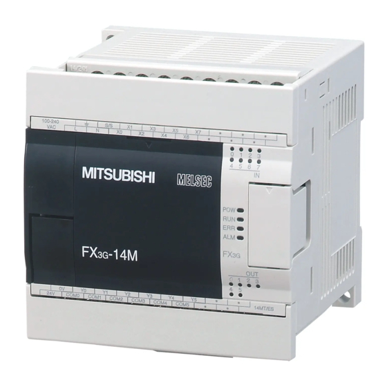
PROGRAMMABLE LOGIC CONTROLLER
MODEL
FX3G
INSTALLATION MANUAL
Table of
Contents
Previous
Page
Next
Page
1
2
3
4
5
Advertisement
Table of Contents
Need help?
Do you have a question about the FX3G-14MR/ES and is the answer not in the manual?
Ask a question
Questions and answers
Related Manuals for Mitsubishi FX3G-14MR/ES
Controller Mitsubishi FX3G-24MR/ES Installation Manual
Programmable logic controller (24 pages)
Controller Mitsubishi FX3G Series Programming Manual
Programmable controllers (944 pages)
Controller Mitsubishi FX3G SERIES User Manual
(382 pages)
Controller Mitsubishi FX3G Series User Manual
Melsec-f, positioning control edition, main unit/sink output/source output, line driver output (240 pages)
Controller Mitsubishi FX3U-4AD User Manual
Fx3g series fx3u series fx3uc series (466 pages)
Controller Mitsubishi FX3G-2AD-BD Installation Manual
Melsec-f fx3g series (3 pages)
Controller Mitsubishi FX3U-USB-BD User Manual
Melsec-f fx series programmable controllers (729 pages)
Controller Mitsubishi FX3G-4EX-BD User Manual
Fx3g series (3 pages)
Controller Mitsubishi MELSEC-F FX3U Series User Manual
(218 pages)
Controller Mitsubishi FX3U SERIES Hardware Manual
(8 pages)
Controller Mitsubishi FX3U SERIES User Manual
(476 pages)
Controller Mitsubishi FX3U Series User Manual
(118 pages)
Controller Mitsubishi FX3U User Manual
Melsec-f, cc-link v2 (260 pages)
Controller Mitsubishi FX3U Series Programming Manual
(890 pages)
Controller Mitsubishi FX3UC SERIES User Manual
(458 pages)
Controller Mitsubishi FX3UC Manual
(13 pages)
This manual is also suitable for:
Fx3g-24mr/es
Fx3g-40mr/es
Fx3g-60mr/es
Table of Contents
Print
Rename the bookmark
Delete bookmark?
Delete from my manuals?
Login
Sign In
OR
Sign in with Facebook
Sign in with Google
Upload manual
Upload from disk
Upload from URL


Need help?
Do you have a question about the FX3G-14MR/ES and is the answer not in the manual?
Questions and answers