Moxa Technologies ioLogik E1200 Series User Manual
Industrial ethernet remote i/o with 2-port ethernet switch
Hide thumbs
Also See for ioLogik E1200 Series:
- User manual (69 pages) ,
- Quick installation manual (9 pages) ,
- User manual (117 pages)

Related Manuals for Moxa Technologies ioLogik E1200 Series


Summary of Contents for Moxa Technologies ioLogik E1200 Series
- Page 1 E1200 Series User’s Manual Eleventh Edition, April 2015 www.moxa.com/product © 2015 Moxa Inc. All rights reserved. Reproduction without permission is prohibited.
-
Page 2: Copyright Notice
E1200 Series User’s Manual The software described in this manual is furnished under a license agreement and may be used only in accordance with the terms of that agreement. Copyright Notice Copyright © 2015 Moxa Inc. All rights reserved. -
Page 3: Table Of Contents
Table of Contents Introduction ............................1-1 Product Features ..........................1-2 Inside the Box ............................ 1-2 Product Model Information ........................1-3 Product Specifications ......................... 1-4 Common Specifications ........................ 1-4 ioLogik E1210 ..........................1-5 ioLogik E1211 ..........................1-5 ioLogik E1212 ..........................1-6 ioLogik E1213 .......................... - Page 4 AO Safe Mode Settings ....................... 3-22 SNMP .............................. 3-22 SNMP Trap ..........................3-22 Using SNMP ..........................3-23 Change Password ..........................3-27 Load Factory Defaults ........................3-28 Save/Restart ............................ 3-28 Using ioSearch™ ..........................4-1 Introduction to ioSearch™ ........................4-2 ioSearch™ Main Screen ........................4-2 Main Screen Overview ........................
-
Page 5: Introduction
Introduction The ioLogik E1200 industrial Ethernet remote I/O has two embedded Ethernet switch ports that allow information to flow to another local Ethernet device or connect to the next ioLogik in the daisy-chain. Applications such as factory automation, security and surveillance systems, and tunnel monitoring, can make use of daisy-chained Ethernet for building multi-drop I/O networks over standard Ethernet cables and familiar fieldbus protocols. -
Page 6: Product Features
E1200 Series Introduction Product Features • Active communication with patented Active OPC Server • 2-port Ethernet switch for daisy-chain topologies • Easy mass deployment and configuration with ioSearch™utility • User-friendly configuration via web browser • Save time and wiring costs with peer-to-peer communication •... -
Page 7: Product Model Information
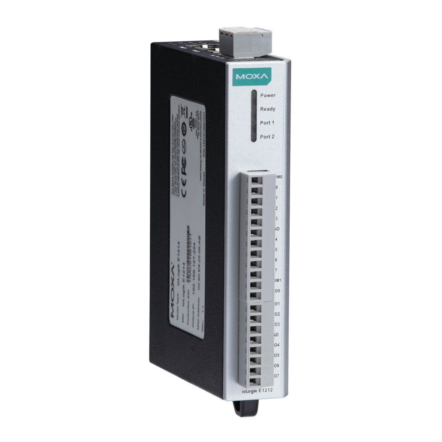
E1200 Series Introduction Product Model Information Model Description ioLogik E1210 Remote Ethernet I/O with 2-port Ethernet switch and 16 DIs ioLogik E1211 Remote Ethernet I/O with 2-port Ethernet switch and 16 DOs ioLogik E1212 Remote Ethernet I/O with 2-port Ethernet switch, 8 DIs, and 8 DIOs... -
Page 8: Product Specifications
E1200 Series Introduction Product Specifications Common Specifications Ethernet: 2 x 10/100 Mbps switch ports, RJ45 Protection: 1.5 kV magnetic isolation Protocols: Modbus/TCP, TCP/IP, UDP, DHCP, BOOTP, HTTP Power Requirements Power Input: 24 VDC nominal, 12 to 36 VDC Physical Characteristics Wiring: I/O cable max. -
Page 9: Iologik E1210
E1200 Series Introduction ioLogik E1210 Inputs and Outputs Digital Inputs: 16 channels Isolation: 3K VDC or 2K Vrms Digital Input Sensor Type: Wet Contact (NPN or PNP), Dry Contact I/O Mode: DI or Event Counter Dry Contact: • On: short to GND •... -
Page 10: Iologik E1212
E1200 Series Introduction ioLogik E1212 Inputs and Outputs Digital Inputs: 8 channels Configurable DIOs: 8 channels Isolation: 3K VDC or 2K Vrms Digital Input Sensor Type: Wet Contact (NPN or PNP), Dry Contact I/O Mode: DI or Event Counter Dry Contact: •... -
Page 11: Iologik E1213
E1200 Series Introduction ioLogik E1213 Inputs and Outputs Digital Inputs: 8 channels Digital Outputs: 4 channels Digital Input/Output (configurable by jumper): 4 channels Isolation: 3K VDC or 2K Vrms Digital Input Sensor Type: NPN, PNP, and dry contact I/O Mode: DI or event counter Dry Contact: •... -
Page 12: Iologik E1214
E1200 Series Introduction ioLogik E1214 Inputs and Outputs Digital Inputs: 6 channels Relay Outputs: 6 channels Isolation: 3K VDC or 2K Vrms Digital Input Sensor Type: Wet Contact (NPN or PNP), Dry Contact I/O Mode: DI or Event Counter Dry Contact: •... -
Page 13: Iologik E1240
E1200 Series Introduction ioLogik E1240 Inputs and Outputs Analog Inputs: 8 channels Isolation: 3K VDC or 2K Vrms Analog Input Type: Differential input Resolution: 16 bits I/O Mode: Voltage / Current Input Range: 0 to 10 VDC, 0 to 20 mA, 4 to 20 mA Accuracy: ±... -
Page 14: Iologik E1242
E1200 Series Introduction ioLogik E1242 Inputs and Outputs Analog Inputs: 4 channels Digital Inputs: 4 channels Configurable DIOs: 4 channels Isolation: 3K VDC or 2K Vrms Analog Input Type: Differential input Resolution: 16 bits I/O Mode: Voltage / Current... -
Page 15: Iologik E1260
E1200 Series Introduction ioLogik E1260 Inputs and Outputs RTD Inputs: 6 channels Isolation: 3K VDC or 2K Vrms RTD Inputs Input Type: • PT50, PT100, PT200, PT500 (-200 to 850°C) • PT1000 (-200 to 350°C) • Resistance of 310, 620, 1250, and 2200 ohms Sampling Rate: •... -
Page 16: Physical Dimensions
E1200 Series Introduction Physical Dimensions 1-12... -
Page 17: Hardware Reference
E1200 Series Introduction Hardware Reference Panel Guide NOTE The RESET button restarts the server and resets all settings to factory defaults. Use a pointed object such as a straightened paper clip to hold down the RESET button for 5 seconds. The factory defaults will be loaded once the READY LED turns green again. -
Page 18: I/O Circuit Diagram
E1200 Series Introduction I/O Circuit Diagram DI Circuit Sinking DO Circuit 1-14... -
Page 19: Sourcing Do Circuit
E1200 Series Introduction Sourcing DO Circuit 1-15... -
Page 20: Dio Circuit
E1200 Series Introduction DIO Circuit 1-16... -
Page 21: Relay Circuit
E1200 Series Introduction Relay Circuit AI Circuit RTD Circuit 1-17... -
Page 22: Tc Circuit
E1200 Series Introduction TC Circuit 1-18... -
Page 23: Initial Setup
Initial Setup This chapter describes how to install the ioLogik E1200. The following topics are covered in this chapter: Hardware Installation Connecting the Power Grounding the ioLogik E1200 DIN Rail, Wall Mounting Connecting to the Network ... -
Page 24: Hardware Installation
E1200 Series Initial Setup Hardware Installation Connecting the Power Connect the 12 to 36 VDC power line to the ioLogik E1200’s terminal block on the top panel. If power is properly supplied, the Power LED will glow a solid amber color. -
Page 25: Connecting To The Network
E1200 Series Initial Setup Connecting to the Network The ioLogik E1200 has two built-in RJ45 Ethernet ports for connecting a standard direct or cross-over Ethernet cable to either the host PC or another ioLogik E1200 device. For initial setup of the ioLogik E1200, it is recommended that the ioLogik E1200 be configured using a direct connection to a host computer rather than remotely over the network. - Page 26 E1200 Series Initial Setup DIO Mode Configuration Settings DIO mode configuration settings are shown below: The default setting is DO Mode. AI Mode Configuration Settings Analog mode configuration settings are shown below: The default setting is Voltage Mode. EXT Power Configuration Settings (ioLogik E1213 Only) The ioLogik E1213 digital outputs have 3 possible external (EXT) power configurations.
-
Page 27: I/O Wiring Diagrams
E1200 Series Initial Setup I/O Wiring Diagrams A Dry Contact is a contact that does not provide voltage. A Wet Contact is a contact that will provide voltage when closed. ATTENTION Remove the screw on the back panel and open the cover to configure the jumpers. - Page 28 E1200 Series Initial Setup NOTE It is recommended to use a contact protection circuit for relay output. A varistor can serve as a contact protection circuit, where the parallel circuit connects to the Load. Load NOTE A “load” in a circuit schematic is a component or portion of the circuit that consumes electric power. For the...
-
Page 29: Iosearch™ Installation
E1200 Series Initial Setup ioSearch™ Installation ioSearch™ is a search utility that helps the user locate ioLogik E1200 devices on the local network. Find the ioSearch™ utility in the Document and Software CD under Software ioSearch, or download the latest version from Moxa’s website. -
Page 30: Using The Web Console
Using the Web Console The ioLogik E1200’s main configuration and management utility is the built-in web console, which can be used to configure a wide range of options. The following topics are covered in this chapter: Introduction to the Web Console ... -
Page 31: Introduction To The Web Console
E1200 Series Using the Web Console Introduction to the Web Console The ioLogik E1200 web console is a browser-based configuration utility. When the ioLogik E1200 is connected to your network, you may enter the server’s IP address in your web browser to access the web console. -
Page 32: Overview
E1200 Series Using the Web Console Overview The Overview page contains basic information about the ioLogik E1200, including the model name, serial number, firmware version, MAC address, and current IP address. Most importantly, you can see the current I/O... -
Page 33: Network Settings For The Web Console
E1200 Series Using the Web Console Network Settings for the Web Console General Settings On the General Settings page, you can assign a server name and location to assist you in differentiating between different ioLogik E1200 units. You may also configure the Modbus/TCP timeout interval or enable the Communication Watchdog function. -
Page 34: User-Defined Modbus Addressing
E1200 Series Using the Web Console User-Defined Modbus Addressing The input and output address can be configured in a different format on a specific settings page. Check the Enable User-defined Modbus Addressing box, select the Modbus function, and then configure the start address of each item. -
Page 35: Active Opc Server Settings
E1200 Series Using the Web Console Active OPC Server Settings Moxa’s Active OPC Server™ is a software package operated as an OPC driver of an HMI or SCADA system. It seamlessly connects Moxa’s ioLogik products to a wide variety of SCADA systems, including the most popular: Wonderware, Citect, and iFix. - Page 36 E1200 Series Using the Web Console 4. Click the Submit button and then the Save/Restart button on the next page. 5. On the Create AOPC Tag page, click on the Create Tags button to “push” tag configurations to the Active OPC Server utility.
-
Page 37: I/O Settings
E1200 Series Using the Web Console I/O Settings DI Channels The status of each DI (digital input) channel appears on the DI Channel Settings page. You can also configure each channel’s digital input mode and parameters by clicking on the channel. DI channels can operate in DI mode or Event Counter mode. - Page 38 E1200 Series Using the Web Console NOTE The Host Connection Watchdog is disabled by default, and must be enabled for Safe Status settings to take effect. Save Status On Power Failure: The ioLogik E1200 will automatically save the counter value when there is a power failure if this function selected.
-
Page 39: Do Channels
E1200 Series Using the Web Console DO Channels On the I/O Setting: DO (Digital Output) Channels page, you can configure each DO channel by clicking on the channel. DO channels can operate in DO mode when the status is either ON or OFF. -
Page 40: Ai Channels
E1200 Series Using the Web Console The DO channel’s Alias Name and logic definition can also be configured on this page. You can apply the alias name to all channels by click on the Apply to all DO channels box. -
Page 41: Ai Input Range
E1200 Series Using the Web Console Click on a specific AI channel to enable or disable it by selecting the Enable AI Channel field. There are two modes available for the AI channels: 1. Voltage Mode (See the Jumper Settings (DIO and AI) in Chapter 2 for more details) 2. - Page 42 E1200 Series Using the Web Console AI Input: Current Mode Burn Out mode indicates when the Current AI has burned out. For example, the 4–20 mA Burn Out mode is defined in the following diagram: Users can define Burn Out (BO) values (default = 2 mA) for selected ranges. When input values are in the Burn Out range, raw data will register as 0000h to indicate that the analog input has burned out.
-
Page 43: Ao Channels
E1200 Series Using the Web Console Selecting Enable Point-Slope formula on the Auto Scaling Settings page will linearly convert the actual current or voltage value into other user-defined units, such as percentage or ppm (parts per million). NOTE The scaled value’s Modbus address differs from the original value. -
Page 44: Rtd Channels
E1200 Series Using the Web Console Enabling the Point-Slope Formula function on the Auto Scaling Settings page will linearly convert the actual current or voltage value into other user-defined units, such as percentage or ppm (parts per million). NOTE The scaled value’s Modbus address differs from the original value. - Page 45 E1200 Series Using the Web Console The ioLogik E1200 allows you to calibrate the temperature sensors. In each channel configuration section, follow the instructions and click Calibrate button to start the RTD sensor calibration. Each calibration requires around 30 seconds per channel.
-
Page 46: Tc Channels
E1200 Series Using the Web Console TC Channels The current status of each TC (Thermocouple) channel can be viewed on the TC Channel page. Click on a specific channel to enable or disable the TC channel. Select the Enable TC Channel checkbox and then select the sensor type that meets the physical attachment to the ioLogik E1200. -
Page 47: System Management
E1200 Series Using the Web Console The ioLogik E1200 allows you to manually adjust the current temperature reading. In each channel configuration section, select the channel, apply the offset value, and click the Submit button. System Management Accessibility IP List You can control network access to the ioLogik E1200 from the Accessibility IP List page by enabling access only from specific IP addresses. -
Page 48: Network Connection
E1200 Series Using the Web Console Allowed Hosts IP Address/Netmask Any host Disable 192.168.1.120 192.168.1.120 / 255.255.255.255 192.168.1.1 to 192.168.1.254 192.168.1.0 / 255.255.255.0 192.168.0.1 to 192.168.255.254 192.168.0.0 / 255.255.0.0 192.168.1.1 to 192.168.1.126 192.168.1.0 / 255.255.255.128 192.168.1.129 to 192.168.1.254 192.168.1.128 / 255.255.255.128 Network Connection TCP connections from other hosts appear on the Network Connection page. -
Page 49: Export System Settings
E1200 Series Using the Web Console Export System Settings On the Export System Settings page, you can export a copy of the ioLogik’s configuration file for backup or import into another ioLogik server. Peer-to-Peer Networking In some remote automation implementations, the control room and field sensors may be spread far apart from each other, often with only a single remote I/O module to collect data from all the sensors. -
Page 50: Sample Peer-To-Peer Configuration
E1200 Series Using the Web Console Sample Peer-to-Peer Configuration The following is an example of configuring DO (Server IP: 192.168.127.253) to DI (Client IP: 192.168.127.252) peer-to-peer functionality with two ioLogik E1200 devices. Server Settings: Client Settings: NOTE Refer to the table below for maximum number of rules supported at different signal frequencies. -
Page 51: Do Safe Mode Settings
SNMP network management software, which is useful for building automation and telecommunications applications. SNMP Trap The ioLogik E1200 series remote I/O provides standard SNMP traps and private SNMP traps for I/O devices. Standard Trap The ioLogik E1200 series remote I/O provides the following standard SNMP traps:... -
Page 52: Using Snmp
E1200 Series Using the Web Console Private Trap The ioLogik E1200 series remote I/O provides the following private trap triggers: Trigger Type Description DI-change status Sends SNMP trap when DI status changes. DO-change status Sends SNMP trap when DI status changes. - Page 53 E1200 Series Using the Web Console SNMP Trap Enable Channel SNMP Trap by clicking on the SNMP Trap box, and then select the channel you would like to enable. NOTE SNMP is not supported while using the peer-to-peer function.
- Page 54 E1200 Series Using the Web Console Analog Input Trap Settings For Analog Input, the trap is triggered when an analog input meets the preset conditions for Trigger, Value, and Hysteresis. Refer to the AI Channel settings in Chapter 3 to set the mode.
- Page 55 E1200 Series Using the Web Console RTD Input Trap Settings For RTD Input, the trap is triggered when the RTD input meets the preset conditions for Trigger, Value, and Hysteresis. Refer to RTD Channel settings to set the Mode and Range.
-
Page 56: Change Password
E1200 Series Using the Web Console When Trigger = Smaller, Value = 400, and Hysteresis = 200, the SNMP trap will only be triggered if the TC signal fluctuates from 600 to 400, like in scenario 1. If we change to Value = 400 and Hysteresis = 400, the SNMP trap will only be triggered if the TC signal fluctuates from 800 to 400. -
Page 57: Load Factory Defaults
E1200 Series Using the Web Console Load Factory Defaults This function will reset all of the ioLogik E1200’s settings to the factory default values. All previous settings, including the console password, will be lost. Save/Restart If you change the configuration, do not forget to reboot the system. -
Page 58: Using Iosearch
Using ioSearch™ This chapter describes ioSearch™, which is used to search for and locate ioLogik E1200 units. The following topics are covered in this chapter: Introduction to ioSearch™ ioSearch™ Main Screen Main Screen Overview ioSearch™ Setup ... -
Page 59: Introduction To Iosearch
E1200 Series Using ioSearch™ Introduction to ioSearch™ Moxa’s ioSearch™ utility is software tool that searches for ioLogik E1200 units on a physical network. The following functions are supported by the ioSearch™ utility: • Search for and locate ioLogik E1200 units •... -
Page 60: Iosearch™ Setup
E1200 Series Using ioSearch™ ioSearch™ Setup System Several operations are possible from the System menu. Auto Scan Active Ethernet I/O Servers will search for ioLogik servers on the network. When connecting for the first time or recovering from a network disconnection, you can use this command to find I/O servers that are on the network. -
Page 61: Sort
E1200 Series Using ioSearch™ Sort The Sort menu allows the server list in the navigation panel to be sorted by ioLogik connection and server (model). Quick Links Quick links are provided to search for I/O servers on the network and sort the server list. -
Page 62: Locate
E1200 Series Using ioSearch™ Locate The locate function helps users find a dedicated ioLogik on the network. When this function is triggered, the ready LED on the selected unit will start to blink indicating its location. Firmware Upgrade The ioLogik E1200 supports a remote firmware upgrade function. Enter the path to the firmware file or click on the icon to browse for the file. -
Page 63: Import
E1200 Series Using ioSearch™ Import Select this command to reload a configuration that was exported to a text file. Importing one configuration file to multiple ioLogik E1200 units (same model) is allowed. To do this, press the “Shift” key, select “ioLogik”, and then right click. -
Page 64: Change Ip Address
E1200 Series Using ioSearch™ Change IP Address The Change IP Address function allows you to directly modify the IP address for one or multiple ioLogik E1200 series devices, and is especially useful for first time installation. First, select the ioLogik E1200 device(s) you wish to modify. Then, right-click on the device(s) and select “Change IP Address”... -
Page 65: Restart System
E1200 Series Using ioSearch™ After clicking the Advance button, a window will pop up to allow users to use ioSearch™ to set the IP address by MAC address. ioSearch™ will automatically set sequential IP addresses on the selected devices, with the subnet mask and gateway set to the same value. -
Page 66: Mass Deployment (Import)
E1200 Series Using ioSearch™ Mass Deployment (Import) Users can import E1200 series module information via ioSearch™. Select this command to reload a configuration from an exported .CSV file. Mass Deployment (Export) Users can export E1200 series module information via ioSearch™. The export file format will be... -
Page 67: Active Opc Server
Active OPC Server Active OPC Server is a software package provided by Moxa that operates as an OPC driver for an HMI or SCADA system. It offers seamless connection from Moxa's ioLogik series products to SCADA systems, such as Wonderware, Citect, and iFix. Active OPC Server meets the latest standard of OPC DA 3.0, which allows connections to various kinds of devices and host OPC machines. -
Page 68: Introduction To Active Opc Server
OPC Server Specifications OPC Data Access 1.0a, 2.0, 2.05a, 3.0 Max. tags ioLogik Support Product Model ioLogik E1200 series, E2200 series, E4200, and W5300 series Firmware version V3.0 or above ioAdmin version V3.0 or above NOTE The latest versions are Active OPC Server V1.11 and ioAdmin 3.10. Use firmware V1.3 or above for the ioLogik W5312 series, V1.5 or above for the ioLogik W5340 series, and V1.2 or above for the ioLogik W5340-HSDPA... -
Page 69: Active Opc Server-From Pull To Push
E1200 Series Active OPC Server OPC Client/Server creates a common interface to connect to different devices Active OPC Server—From Pull to Push When looking up an I/O devices’ Modbus table, 19 or more steps are required to create a single tag. The steps include specifying the IP address, selecting the protocols, and defining the data type. - Page 70 E1200 Series Active OPC Server DI_1=ON DI_1=OFF DI_0=ON DI_0=OFF ioLogik Tag Update ioLogik Idle...
-
Page 71: Features Of Active Opc Server
E1200 Series Active OPC Server Features of Active OPC Server One Simple Click Creates Active Tags Moxa’s RTUs, remote I/O devices, and Active OPC Servers support automatic tag generation, which eliminates the headache of specifying individual target IP addresses, I/O channels, and data formats, while even eliminating any need for editing and importing configuration files. -
Page 72: Dynamic Ip Assignments For Cellular Rtus
E1200 Series Active OPC Server Dynamic IP Assignments for Cellular RTUs For most cellular solutions, each remote modem as well as the central SCADA server are assigned static public IPs when establishing bi-directional communication. Yet cellular network carriers charge higher monthly fees for static, public IPs than dynamic, private ones. -
Page 73: Main Screen Overview
E1200 Series Active OPC Server Main Screen Overview Active OPC Server Lite’s main screen displays a figure of the mapped iologik with the status of every I/O tag. Note that configuration and tags are not available until you set the ioLogik to create the tags. - Page 74 E1200 Series Active OPC Server System Several operations can be accessed from the System menu. Network Interface: Select which network to use if the PC has multiple network adaptors installed. Active Tag Listen Port: Select the preferred TCP socket port for tag generation from ioAdmin.
- Page 75 E1200 Series Active OPC Server System Log Settings: Enable or disable the Active OPC Server system log function. It will keep a Log file of all the Logging information. Launch DCOM Configuration: Launch the Windows DCOM configuration utility. Register OPC as Service: Force Active OPC Server to run as a Windows system service.
-
Page 76: Modbus/Tcp Default Address Mappings
Modbus/TCP Default Address Mappings The following topics are covered in this appendix: E1210 Modbus Mapping E1211 Modbus Mapping E1212 Modbus Mapping E1213 Modbus Mapping E1214 Modbus Mapping E1240 Modbus Mapping E1241 Modbus Mapping ... -
Page 77: E1210 Modbus Mapping
E1200 Series Modbus/TCP Default Address Mappings NOTE The Modbus/TCP ID of the ioLogik E1200 is set to “1” by default. E1210 Modbus Mapping 0xxxx Read/Write Coils (Functions 1, 5, 15) Reference Address Data Type Description 00257 0x0100 1 bit... - Page 78 E1200 Series Modbus/TCP Default Address Mappings Reference Address Data Type Description 00280 0x0117 1 bit CH7 DI Clear Count Value Read Always return:0 Write: 1 : Clear counter value 0 : Return illegal data value(0x03) 00281 0x0118 1 bit...
- Page 79 E1200 Series Modbus/TCP Default Address Mappings 1xxxx Read Only Coils (Function 2) Reference Address Data Type Description CH0 DI Value,0=OFF,1=ON (Read only) 10001 0x0000 1 bit CH1 DI Value,0=OFF,1=ON (Read only) 10002 0x0001 1 bit CH2 DI Value,0=OFF,1=ON (Read only)
-
Page 80: E1211 Modbus Mapping
E1200 Series Modbus/TCP Default Address Mappings Reference Address Data Type Description 30046 0x002D 1 word CH14 DI Counter Value Lo- Word (Read only) 30047 0x002E 1 word CH15 DI Counter Value Hi- Word (Read only) 30048 0x002F 1 word... - Page 81 E1200 Series Modbus/TCP Default Address Mappings Reference Address Data Type Description Read: always zero 04132 0x1023 1 bit CH3 DO Clear P2P Output Safe Status Write: 1= clear status Read: always zero 04133 0x1024 1 bit CH4 DO Clear P2P Output Safe Status Write: 1= clear status...
-
Page 82: E1212 Modbus Mapping
E1200 Series Modbus/TCP Default Address Mappings Reference Address Data Type Description 14117 0x1014 1 bit CH4 DO P2P Output Safe Status 0=Normal, 1=Safe Mode 14118 0x1015 1 bit CH5 DO P2P Output Safe Status 0=Normal, 1=Safe Mode 14119 0x1016... - Page 83 E1200 Series Modbus/TCP Default Address Mappings Reference Address Data Type Description 00271 0x010E 1 bit CH14 DI Counter Operate Status 0: Stop 1: Start(R/W) 00272 0x010F 1 bit CH15 DI Counter Operate Status 0: Stop 1: Start(R/W) 00273 0x0110...
- Page 84 E1200 Series Modbus/TCP Default Address Mappings Reference Address Data Type Description 0 : Return illegal data value(0x03) 00286 0x011D 1 bit CH13 DI Clear Count Value Read Always return:0 Write: 1 : Clear counter value 0 : Return illegal data value(0x03)
- Page 85 E1200 Series Modbus/TCP Default Address Mappings 1xxxx Read Only Coils (Function 2) Reference Address Data Type Description CH0 DI Value,0=OFF,1=ON (Read only) 10001 0x0000 1 bit CH1 DI Value,0=OFF,1=ON (Read only) 10002 0x0001 1 bit CH2 DI Value,0=OFF,1=ON (Read only)
- Page 86 E1200 Series Modbus/TCP Default Address Mappings 3xxxx Read Only Registers (Function 4) Reference Address Data type Description 30017 0x0010 1 word CH0 DI Counter Value Hi- Word (Read only) 30018 0x0011 1 word CH0 DI Counter Value Lo- Word (Read only)
-
Page 87: E1213 Modbus Mapping
E1200 Series Modbus/TCP Default Address Mappings E1213 Modbus Mapping 0xxxx Read/Write Coils (Functions 1, 5, 15) Reference Address Data Type Description DO Channel 00001 0x0000 1 bit CH0 DO Value 0: Off 1: On 00002 0x0001 1 bit CH1 DO Value 0: Off 1: On... - Page 88 E1200 Series Modbus/TCP Default Address Mappings Reference Address Data Type Description Read Always return: 0 Write: 1 : Clear counter value 0 : Return illegal data value(0x03) 00275 0x0112 1 bit CH2 DI Clear Count Value Read Always return: 0...
- Page 89 E1200 Series Modbus/TCP Default Address Mappings Reference Address Data Type Description 10006 0x0005 1 bit CH5 DI Value, 0=OFF, 1=ON (Read only) 10007 0x0006 1 bit CH6 DI Value, 0=OFF, 1=ON (Read only) 10008 0x0007 1 bit CH7 DI Value, 0=OFF, 1=ON (Read only)
- Page 90 E1200 Series Modbus/TCP Default Address Mappings 3xxxx Read Only Registers (Function 4) Reference Address Data type Description 30017 0x0010 1 word CH0 DI Counter Value Hi- Word (Read only) 30018 0x0011 1 word CH0 DI Counter Value Lo- Word (Read only)
-
Page 91: E1214 Modbus Mapping
E1200 Series Modbus/TCP Default Address Mappings E1214 Modbus Mapping 0xxxx Read/Write Coils (Functions 1, 5, 15) Reference Address Data Type Description DO Channel 00001 0x0000 1 bit CH0 DO (Relay) Value 0: Off 1: On 00002 0x0001 1 bit... - Page 92 E1200 Series Modbus/TCP Default Address Mappings Reference Address Data Type Description Read Always return:0 Write: 1 : Clear counter value 0 : Return illegal data value(0x03) 00276 0x0113 1 bit CH3 DI Clear Count Value Read Always return:0 Write:...
-
Page 93: E1240 Modbus Mapping
E1200 Series Modbus/TCP Default Address Mappings 3xxxx Read Only Registers (Function 4) Reference Address Data Type Description 30017 0x0010 1 word CH0 DI Counter Value Hi- Word (Read only) 30018 0x0011 1 word CH0 DI Counter Value Lo- Word (Read only) - Page 94 E1200 Series Modbus/TCP Default Address Mappings Reference Address Data Type Description 30013 0x000C 1 word CH2 Read AI Scaling Value Hi (float) 30014 0x000D 1 word CH2 Read AI Scaling Value Low (float) 30015 0x000E 1 word CH3 Read AI Scaling Value Hi (float)
-
Page 95: E1241 Modbus Mapping
E1200 Series Modbus/TCP Default Address Mappings 3xxxx Read Only Registers (Function 4) Reference Address Data Type Description 40025 0x0018 1 word CH AI 0 Mode: 1:4-20mA, 2:0-20mA, 4:BO 40026 0x0019 1 word CH AI 1 Mode: 1:4-20mA, 2:0-20mA, 4:BO... -
Page 96: E1242 Modbus Mapping
E1200 Series Modbus/TCP Default Address Mappings 3xxxx Read Only Registers (Function 4) Reference Address Data Type Description 30001 0x0000 2 words CH0 Read AO Scaling Value (float) 30002 0x0001 2 words CH1 Read AO Scaling Value (float) 30003 0x0002... - Page 97 E1200 Series Modbus/TCP Default Address Mappings Reference Address Data Type Description 00276 0x0113 1 bit CH3 DI Clear Count Value Read Always return:0 Write: 1 : Clear counter value 0 : Return illegal data value(0x03) 00277 0x0114 1 bit...
- Page 98 E1200 Series Modbus/TCP Default Address Mappings Reference Address Data Type Description 14115 0x1012 1 bit CH2 DO P2P Output Safe Status 0=Normal, 1=Safe Mode 14116 0x1013 1 bit CH3 DO P2P Output Safe Status 0=Normal, 1=Safe Mode 3xxxx Read Only Registers (Function 4)
-
Page 99: E1260 Modbus Mapping
E1200 Series Modbus/TCP Default Address Mappings Reference Address Data Type Description 2: Over Range 3. Under Range 30580 0x0243 1 word Read AI 3 Current Mode Status 0: Normal 1: Burn Out 2: Over Range 3. Under Range 4xxxx Read/Write Registers (Functions 3, 6, 16) -
Page 100: E1262 Modbus Mapping
E1200 Series Modbus/TCP Default Address Mappings E1262 Modbus Mapping 3xxxx Read Only Registers (Function 4) Reference Address Data Type Description 32049 0x0800 1 word CH0 TC Value Hi Word Unit:0.1 (Celsius, Fahrenheit) 0.0001(mV) 32050 0x0801 1 word CH0 TC Value Lo Word Hi+Lo Range: 0–4294967295... -
Page 101: Network Port Numbers
Network Port Numbers ioLogik E1200 Network Port Usage Port Type Usage Web console service Modbus/TCP communication BOOTP/DHCP 4800 Auto search Export/import configuration file 9900 Active OPC Server 9500 Active OPC Server 9020 (default) Peer-to-peer... -
Page 102: Factory Default Settings
Factory Default Settings ioLogik E1200 series products are configured with the following factory default settings: Default IP address 192.168.127.254 Default Netmask 255.255.255.0 Default Gateway 0.0.0.0 Communication watchdog Disable Modbus/TCP Alive Check Modbus/TCP Timeout Interval 60 sec DI Mode Filter time... -
Page 103: Pinouts
Pinouts Pin Assignment of Terminal Blocks NOTE EX_V: External Voltage EX_C: External Com... -
Page 104: Fcc Interference Statement
FCC Interference Statement Federal Communication Commission Warning! This equipment has been tested and found to comply with the limits for a Class A digital device, pursuant to part 15 of the FCC Rules. Operation is subject to the following two conditions: (1) This device may not cause harmful interference, and (2) this device must accept any interference received, including interference that may cause undesired operation. -
Page 105: European Community (Ce
European Community (CE) This is a Class A product. In a domestic environment, this product may cause radio interference in which case the user may be required to take adequate measures.
Need help?
Do you have a question about the ioLogik E1200 Series and is the answer not in the manual?
Questions and answers