
Subscribe to Our Youtube Channel
Related Manuals for Moxa Technologies EDR-G9010 Series


Summary of Contents for Moxa Technologies EDR-G9010 Series
- Page 1 EDR-G9010 Series User Manual Version 2.0, September 2022 www.moxa.com/products © 2022 Moxa Inc. All rights reserved.
- Page 2 EDR-G9010 Series User Manual The software described in this manual is furnished under a license agreement and may be used only in accordance with the terms of that agreement. Copyright Notice © 2022 Moxa Inc. All rights reserved. Trademarks The MOXA logo is a registered trademark of Moxa Inc.
-
Page 3: Table Of Contents
Table of Contents Introduction ............................6 Overview .............................. 6 Package Checklist ..........................6 Features ............................... 6 Defend Against Malicious Threats With Advanced Cybersecurity Features ..........7 Simplify Configurations With the User-friendly Interface and Quick Settings .......... 7 Industrial-grade Design to Ensure Uninterrupted Network Connectivity ..........7 Virtual Patching and Intelligent Threat Protection ................ - Page 4 Secondary IP ..........................100 Redundancy ............................102 Layer 2 Redundancy........................... 102 Spanning Tree ........................... 102 Turbo Ring V2 ..........................106 Layer 3 Redundancy........................... 110 VRRP ............................110 Network Service ..........................114 DHCP Server ............................. 114 General Settings ........................114 DHCP ............................115 MAC-based IP Assignment ......................
- Page 5 IPsec Configuration ..........................206 Global Settings .......................... 206 IPsec Settings ..........................207 IPsec Use Case Demonstration ..................... 213 IPsec Status ..........................217 L2TP Server (Layer 2 Tunnel Protocol) ....................217 L2TP Server Setting (WAN) ......................217 L2TP User Name Settings ......................218 Site-to-site IPsec VPN tunnel with Pre-Shared Key .................
-
Page 6: Introduction
In addition, wide temperature models are available that operate reliably in hazardous, -40 to 75°C environments. The EDR-G9010 Series is a set of highly integrated industrial multi-port secure routers with firewall/NAT/VPN and managed Layer 2 switch functions. These devices are designed for Ethernet-based security applications in critical remote control or monitoring networks. -
Page 7: Defend Against Malicious Threats With Advanced Cybersecurity Features
Simplify Configurations With the User-friendly Interface and Quick Settings The EDR-G9010 Series’ “Interface Type Quick Settings” provide an easy way for users to set up WAN, LAN, and Bridge ports for routing functionality in just four steps. In addition, the “Quick Automation Profile”... -
Page 8: Getting Started
After installing PComm Terminal Emulator, perform the following steps to access the RS-232 console utility. From the Windows desktop, click Start > Moxa > PComm Terminal Emulator. Click Open in the Port Manager menu to open a new connection. EDR-G9010 Series User Manual... - Page 9 COM port from the Serial Parameters list and configure the following values: Baud Rate: 115200 Data Bits: 8, Parity: None Stop Bits: 1. Click the Terminal tab, select VT100 for Terminal Type, then click OK to continue. EDR-G9010 Series User Manual...
- Page 10 Save the running configuration to flash ping Send echo messages tcpdump Dump traffic on a network clear Clear information show Show system information configure Enter Configuration Mode sslcertgen Generate a SSL certificate sshkeygen Generate a SSH host key EDR-G9010 Series User Manual...
-
Page 11: Using Telnet To Access The Industrial Secure Router's Console
Ethernet cable. NOTE The Industrial Secure Router’s default LAN IP address is 192.168.127.254. Perform the following steps to access the console utility via Telnet. Click Start > Windows System > Run from the Windows desktop. EDR-G9010 Series User Manual... -
Page 12: Using A Web Browser To Configure The Industrial Secure Router
To use the Industrial Secure Router’s management and monitoring functions from a PC host connected to the same LAN as the Industrial Secure Router, you must make sure that the PC host and the Industrial Secure Router are connected to the same logical subnet. EDR-G9010 Series User Manual... - Page 13 You may need to wait a few moments for the web interface to appear. If you have logged in before, a system message will appear showing the details of the last successful login. Click CLOSE to close this message. EDR-G9010 Series User Manual...
- Page 14 After successfully connecting to the router, the Device Summary screen will automatically appear. Use the menu tree on the left side of the window to open the function pages to access each of the router’s functions. EDR-G9010 Series User Manual...
-
Page 15: Device Summary And Setup Wizard
Click on a function name in the Function Menu on the left-hand side to view or configure the function. All the configuration options and information of the selected function will be shown here. This shows the name of the logged in user. EDR-G9010 Series User Manual... - Page 16 Click RESET to reset the Industrial Secure Router to the factory default settings. Be aware that all your configuration settings will be permanently deleted. NOTE After resetting the device, you will need to use the default network settings to re-establish a web-browser or Telnet connection to your Industrial Secure Router. EDR-G9010 Series User Manual...
-
Page 17: Device Summary
This overview page contains basic activity and performance information of the device. If you are on another configuration page, click Device Summary from the Function Menu to jump to the summary page. See the following sections for a more detailed description of each widget on the summary page. EDR-G9010 Series User Manual... -
Page 18: Model Information
This panel illustrates the panel status. For example, the connecting ports will be shown in green, while the disconnected ports will be shown in gray. Click to view more detailed information. Click to hide the details. EDR-G9010 Series User Manual... -
Page 19: Event Summary (Last 3 Days)
The panel view figure varies depending on the product model you are using. Event Summary (Last 3 Days) This panel shows the event summary for the past three days. Click to go to the Event Log page, where you can view all event logs in more detail. EDR-G9010 Series User Manual... -
Page 20: Cpu Usage History (%)
For Event Log settings, refer to the Event Log section. CPU Usage History (%) This panel shows the device’s CPU usage. The data will be shown as a percentage over time. Click the icon to refresh the graph. EDR-G9010 Series User Manual... -
Page 21: Memory Usage History (%)
This panel shows the device’s memory usage. The data will be shown as a percentage over time. Click the icon to refresh the graph. Setup Wizard The EDR-G9010 Series supports a Setup Wizard to help you quickly set up routing functionality between the user-defined LAN, WAN, and Bridge ports. Step 1: Port Type Select the port type (LAN, WAN, Bridge) for each port from the corresponding drop-down menu. -
Page 22: Step 2: Interface
Get the WAN IP address from a DHCP server or via a PPTP Dynamic IP connection. Specify a static WAN IP address or create a connection to a Dynamic IP Static IP PPTP server with a specific IP address. PPPoE Get the WAN IP address via PPPoE Dialup. EDR-G9010 Series User Manual... - Page 23 Dynamic IP Static IP PPPoE EDR-G9010 Series User Manual...
-
Page 24: Step 3: Service
Enable N-1 NAT are enabled by default. The default IP address range will be set automatically. To modify the IP range, refer to the DHCP Server section. Step 4: Confirm Click APPLY to apply the settings or click BACK to modify the settings. EDR-G9010 Series User Manual... - Page 25 NOTE The settings configured in the Setup Wizard will override any existing configuration. EDR-G9010 Series User Manual...
-
Page 26: System
From the System menu, you can access the System Management, Account Management, License Management, Management Interface, Time, and Setting Check configuration pages. System Management From the System Management menu, the following functions can be configured: Information Settings, Firmware Upgrade, Software Package Management, and Configure Backup and Restore. EDR-G9010 Series User Manual... -
Page 27: Information Settings
Enter the contact information for the person in charge of the device. This is useful for providing information on who is Max. 40 characters None responsible for maintaining this unit and how to contact this person. When finished, click APPLY to save your changes. EDR-G9010 Series User Manual... -
Page 28: Firmware Upgrade
IP address None firmware file (*.rom) is located. File Name Setting Description Factory Default Firmware file name Enter the file name of the target firmware file. None When finished, click UPGRADE to start the firmware upgrade process. EDR-G9010 Series User Manual... - Page 29 This procedure will take several minutes to complete. NOTE The ABC-02 USB is an optional accessory and must be purchased separately. NOTE If you have difficulties using the ABC-02 configuration tool, check if the USB Function has been enabled in Hardware Interface section. EDR-G9010 Series User Manual...
-
Page 30: Software Package Management
No package is installed. Source Select the source for installing or upgrading the security package. There are two ways to install or upgrade security packages: using a local file or through a firmware file. Refer to the following sections. EDR-G9010 Series User Manual... - Page 31 Select Local from the drop-down menu under Source to update an existing package using a local file. Select File Click to select the package file stored locally on the host computer. With the package selected, click UPGRADE to start the upgrade process. This procedure will take several minutes to complete. EDR-G9010 Series User Manual...
-
Page 32: Configuration Backup And Restore
From the Backup screen, you can export the device’s configuration. There are three ways to back up the configuration of your Industrial Secure Router: to the local host computer, to a remote TFTP server, or to a Moxa ABC-02 USB tool. EDR-G9010 Series User Manual... - Page 33 BACK UP to back up the system configuration file to the tool. NOTE If you have difficulties using the ABC-02 configuration tool, check if the USB Function has been enabled in the Hardware Interface section. EDR-G9010 Series User Manual...
- Page 34 Select Local from the drop-down list under Method Select File Click to select a configuration file stored locally on the host computer. With the configuration file selected, click RESTORE to restore the system configuration. This procedure will take several minutes to complete. EDR-G9010 Series User Manual...
- Page 35 Insert the Moxa ABC-02 USB-based configuration tool into the USB port of the Industrial Secure Router and click RESTORE to restore the system configuration. NOTE If you have difficulties using the ABC-02 configuration tool, check if the USB Function has been enabled in the Hardware Interface section. EDR-G9010 Series User Manual...
- Page 36 Encrypt all information Encrypt all information in the exported configuration file. Key String Setting Description Factory Default Enter an encryption key string. This key string is also used to Max. 31 characters moxa decrypt encrypted configuration files. When finished, click Apply to apply the changes. EDR-G9010 Series User Manual...
-
Page 37: Account Management
User-level accounts have read-only access and can only view configurations. NOTE We strongly recommend changing the default password after logging in for the first time. The default ‘admin’ account cannot be deleted and is enabled by default. EDR-G9010 Series User Manual... - Page 38 New Password Setting Description Factory Default 4 to 16 characters Enter a password for the account. None Confirm Password Setting Description Factory Default 4 to 16 characters Re-enter the password for the account to confirm. None EDR-G9010 Series User Manual...
- Page 39 Enter a new password for the account. None Confirm Password Setting Description Factory Default 4 to 16 characters Re-enter the new password for the account to confirm. None When finished, click APPLY to save your changes. EDR-G9010 Series User Manual...
- Page 40 Click DELETE to delete the account Search for an Existing Account Enter the full or partial account username in the Search field. Any user accounts matching the search criteria will be shown in the Account List table. EDR-G9010 Series User Manual...
-
Page 41: Password Policy
Must contain at least one special character (~!@#$%^&*- |:;,.<>{}[]()) Setting Description Factory Default Enable or disable the requirement of the password to contain Enabled or Disabled Disabled at least one special character. EDR-G9010 Series User Manual... -
Page 42: License Management
License Type: The type of license. • Click the icon to refresh the license information. Enter the full or partial license number in the Search field. Any licenses matching the search criteria will be shown in the License List table. EDR-G9010 Series User Manual... - Page 43 Click Next. Click the icon to copy the serial number and store it somewhere where it can be easily copied from. Use the serial number to activate the license in the Moxa license management portal. Click Next. EDR-G9010 Series User Manual...
-
Page 44: Management Interface
Enter the activation code from the email you have received after activating the license in the license management portal. Click APPLY. The license is now activated on the Industrial Secure Router. Management Interface From the Management Interface section, four functions can be configured: User Interface, Hardware Interface, SNMP, and MXsecurity. EDR-G9010 Series User Manual... -
Page 45: User Interface
Enter the TCP port number for HTTP. HTTPS Setting Description Factory Default Enabled or Disabled Enable or disable HTTPS connections. Enabled TCP Port (HTTPS) Setting Description Factory Default 2 to 65535 Enter the TCP port number for HTTPS. EDR-G9010 Series User Manual... - Page 46 Specify the maximum combined number of users that can be 1 to 5 logged in to the Industrial Secure Router using Telnet and SSH. The maximum is 5. When finished, click APPLY to save your changes. EDR-G9010 Series User Manual...
-
Page 47: Hardware Interface
HMAC-SHA algorithms, and data encryption key. 8-character Authentication based Data encryption MD5 or SHA passwords and a data on MD5 or SHA key: DES, AES encryption key are the minimum requirements for authentication and encryption. EDR-G9010 Series User Manual... - Page 48 Use a community string match for authentication public/private Access Control 1/2 Setting Description Factory Default Read Write, or Select the access control type for when the community string Read Only/Read Read only, or is matched Write No Access EDR-G9010 Series User Manual...
- Page 49 The Industrial Secure Router comes with two preconfigured SNMP Accounts which are disabled by default. Modify an Existing SNMP Account In the SNMP Account list, click the icon next to the SNMP account you want to modify. Select Enabled from the Status drop-down menu and configure the following settings: EDR-G9010 Series User Manual...
-
Page 50: Mxsecurity
This section shows the current connection status to MXsecurity, the installed MXsecurity Agent package version, and the profile sync status. Click the Refresh ( ) icon in the upper-right corner to refresh the connection status information. EDR-G9010 Series User Manual... -
Page 51: Time
The Moxa Industrial Secure Router does not feature a real-time clock. If there is no NTP/SNTP server on the network or the device is not connected to the Internet, the Current Time and Current Date must be manually reconfigured after each reboot. EDR-G9010 Series User Manual... - Page 52 Local SNTP Set the clock source to SNTP. Set the clock source to NTP. Local Date Setting Description Factory Default Date Manually set the date in YYYY-MM-DD format. Current date EDR-G9010 Series User Manual...
- Page 53 Specify the IP or domain address of the secondary time server. The Moxa Industrial Secure Router will use the 0 to 60 characters None secondary NTP server if it cannot connect to the primary NTP server. When finished, click APPLY to save your changes. EDR-G9010 Series User Manual...
- Page 54 Daylight Saving The Daylight Saving settings are used to automatically set the Moxa router’s time forward according to national standards. Daylight Saving Status Setting Description Factory Default Enabled or Disabled Enable or disable Daylight Saving time. Disabled EDR-G9010 Series User Manual...
- Page 55 Specify the day the Daylight Saving time begins. None Hour Setting Description Factory Default User-specified hour Specify the hour the Daylight Saving time begins. Minutes Setting Description Factory Default User-specified minutes Specify the minute(s) the Daylight Saving time begins. EDR-G9010 Series User Manual...
-
Page 56: Ntp/Sntp Server
Changing the time zone will automatically adjust the current time. Be sure to set the time zone before setting the time. NTP/SNTP Server NTP/SNTP Server Setting Description Factory Default Enabled or Disabled Enable or disable NTP/SNTP server functionality for clients. Disabled EDR-G9010 Series User Manual... -
Page 57: Setting Check
Specify the time (in seconds) the user has to confirm the changes. If the timer expires and the changes were not 10 to 3600 seconds 180 (seconds) confirmed, the system will automatically revert to the previous settings. EDR-G9010 Series User Manual... - Page 58 Industrial Secure Router. If the new configuration does not block the remote user’s connection to the Industrial Secure Router, the user will see the Setting Check Confirmed page. Click CONFIRM to save and apply the changes. EDR-G9010 Series User Manual...
-
Page 59: Network Configuration
This chapter describes how to configure the physical ports and network interfaces of the Industrial Secure Router. From the Network Configuration section, you can configure the Ports, Layer 2 Switching, and Network Interfaces settings. Ports From the Ports section, the following functions can be configured: Port Settings, and Link Aggregation. EDR-G9010 Series User Manual... -
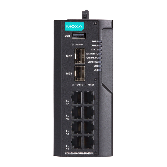
Page 60: Port Settings
Port Settings Port settings let you manage port access, port transmission speed, flow control, and port type (MDI or MDIX). The EDR-G9010 Series has eight RJ45 Ethernet ports and two mini GBIC fiber ports. Setting EDR-G9010 Series User Manual... - Page 61 The port and connected device will determine the best speed for that connection. 1G Full Auto 100M-Full Select a fixed speed and duplex mode if the connected 100M-Half Ethernet device has trouble auto-negotiating the line speed. 10M-Full 10M-Half EDR-G9010 Series User Manual...
- Page 62 When finished, click APPLY to save your changes. Status The Status page shows the current status of the Ethernet ports including the port transmission speed, flow control, and port type (MDI or MDIX). EDR-G9010 Series User Manual...
-
Page 63: Link Aggregation
Communication redundancy will be reset • 802.1Q VLAN will be reset • Multicast Filtering will be reset • Port Lock will be reset and disabled. • • Set Device IP will be reset Mirror will be reset • EDR-G9010 Series User Manual... - Page 64 When finished, click CREATE to save your configuration. Edit Existing Link Aggregation Click the icon to modify the settings for each trunking port. Select the ports you want to add to the link aggregation group and click APPLY. EDR-G9010 Series User Manual...
-
Page 65: Layer 2 Switching
Select the link aggregation groups you want to delete in the Link Aggregation list and click the icon. Click DELETE to delete the selected items. Layer 2 Switching From the Layer 2 Switching section, the following functions can be configured: VLAN, MAC Address Table, QoS, Rate Limit, and Multicast. EDR-G9010 Series User Manual... -
Page 66: Vlan
VLANs increase the efficiency of your network because each VLAN can be set up to contain only those devices that need to communicate with each other. EDR-G9010 Series User Manual... - Page 67 The untagged packet on the Trunk Port will be assigned the default port PVID as its VID. Hybrid Port: The port is similar to a Trunk port, except users can explicitly assign tags to be removed • from egress packets. EDR-G9010 Series User Manual...
- Page 68 VLAN, pass it to port 7, and then remove tags received successfully by Device I. Packets from Device I will travel through Trunk Port 3 with tagged VID 4. Switch A will recognize its VLAN and pass it to port 2, but will not remove tags received successfully by Device E. EDR-G9010 Series User Manual...
- Page 69 Router for quick and easy configuration of VLAN settings for 1 to 10 multiple ports at once. Set the Mode, PVID, Tagged VLAN ID, None and Untagged VLAN ID and click APPLY button to create the VLAN ID configuration table. EDR-G9010 Series User Manual...
- Page 70 Trunk or Hybrid to be removed in egress packets. Use commas to separate mode: None different VIDs. When finished, click APPLY to save your changes. EDR-G9010 Series User Manual...
- Page 71 Settings EDR-G9010 Series User Manual...
- Page 72 None VLANs 4-8, 10-13. When finished, click CREATE to create the VLAN. Delete a VLAN Select the VLAN you want to delete from the list and click the icon. Click DELETE to delete the selected items. EDR-G9010 Series User Manual...
- Page 73 Trunk or Hybrid to be removed in egress packets. Use commas to separate mode: None different VIDs. When finished, click the APPLY button to save your changes. EDR-G9010 Series User Manual...
-
Page 74: Mac Address Table
Moxa router’s MAC Address Table before it is removed. Once a MAC address is removed, the Industrial Secure Router will no longer forward frames originating from this MAC address. To modify the Aging Time, specify the duration (in seconds) and click Apply. EDR-G9010 Series User Manual... -
Page 75: Qos
Quality of Service (QoS) to your network. Moxa switch traffic prioritization is based on two standards: IEEE 802.1p—a Layer 2 QoS marking scheme • Differentiated Services (DiffServ)—a Layer 3 QoS marking scheme. • EDR-G9010 Series User Manual... - Page 76 When the packet reaches the head of its queue and is about to be transmitted, the device determines whether or not the egress port belongs to the VLAN group. If it is, then the new 802.1p tag is used in the extended 802.1D header. EDR-G9010 Series User Manual...
- Page 77 Strict: This method services high traffic queues first; low priority queues are delayed until no more high • priority data needs to be sent. The Strict method always gives precedence to high priority over low priority. CoS Mapping Click the icon to configure the priority queue settings of the corresponding CoS level. EDR-G9010 Series User Manual...
- Page 78 DSCP value. Priority Queue Setting Description Factory Default 0 to 3 Select the egress queue to map to the ToS value. 0 to 3 When finished, click APPLY to save your changes. EDR-G9010 Series User Manual...
- Page 79 Always) the lower priorities to be starved of opportunity for transmitting any frames but ensures that all high priority frames will egress the switch as soon as possible. When finished, click APPLY to save your changes. EDR-G9010 Series User Manual...
- Page 80 Inspect TOS and Inspect CoS can be disabled. This setting leaves only port default priority active, which results in all ingress frames being assigned the same priority on that port. EDR-G9010 Series User Manual...
-
Page 81: Rate Limiting
Ingress Policy Setting Description Factory Default Limit All Limit Broadcast, Flooded Unicast Select the ingress rate limit for different packet types. Limit Broadcast Limit Broadcast, Multicast Limit Broadcast When finished, click APPLY to save your changes. EDR-G9010 Series User Manual... -
Page 82: Multicast
• It makes efficient use of network bandwidth and scales well as the number of multicast group members increases. Works with other IP protocols and services, such as Quality of Service (QoS). • EDR-G9010 Series User Manual... - Page 83 Snooping Mode allows your industrial secure router to forward multicast packets only to the appropriate ports. The router snoops on exchanges between hosts and an IGMP device to find those ports that want to join a multicast group, and then configures its filters accordingly. EDR-G9010 Series User Manual...
- Page 84 Snooping is not enabled, then IP multicast traffic is always forwarded, flooding the network. IGMP Snooping IGMP Snooping provides the ability to prune multicast traffic so that it travels only to those end destinations that require that traffic, thereby reducing the amount of traffic on the Ethernet LAN. EDR-G9010 Series User Manual...
- Page 85 If IGMP Snooping is enabled, select the IGMP Snooping version. V1/V2: Enable the Moxa Industrial Secure Router to send V1/V2, V3 V1/V2 IGMP Snooping Version 1 and 2 queries. V3: Enable the Moxa Industrial Secure Router to send IGMP Snooping Version 3 queries. EDR-G9010 Series User Manual...
- Page 86 • Exclude when IGMP v3 is enabled. Port: Displays the port which receives the multicast stream/the port the multicast stream is forwarded • Source Address: Displays the multicast source address when IGMP v3 is enabled. • EDR-G9010 Series User Manual...
- Page 87 Member port: Displays the port the multicast stream is forwarded from. • Static Multicast Table From the Static Multicast Table, you can create static multicast entries. NOTE 01:00:5E:XX:XX:XX on this page is the IP multicast MAC address. Activate IGMP Snooping for automatic classification. EDR-G9010 Series User Manual...
-
Page 88: Network Interface
1/1, 1/2, 1/3, 1/4, 1/5, Check the boxes to add the corresponding ports to the static 1/6, 1/7, 1/8, 1/9, 1/10 None multicast group. checkbox When finished, click CREATE to create the static multicast entry. Network Interface EDR-G9010 Series User Manual... - Page 89 Subnet mask Specify the subnet mask of the interface. 24 (255.255.255.0) Virtual MAC Setting Description Factory Default Virtual MAC Enter the virtual MAC address of the interface. 00:00:00:00:00:00 When finished, click CREATE to create the new interface. EDR-G9010 Series User Manual...
-
Page 90: Wan
Connection Type Setting Description Factory Default Choose the connection type. For more details and configuration settings for each type, refer to: Static IP, Dynamic IP, Dynamic IP Connection Dynamic IP PPPoE Static IP Connection PPPoE Connection. EDR-G9010 Series User Manual... - Page 91 Dynamic IP Connection Directed Broadcast Status Setting Description Factory Default Enabled or Disabled Enable or disable the directed broadcasting. Enabled Source IP Overwrite Setting Description Factory Default Enabled or Disabled Enable or disable source IP overwriting. Enabled EDR-G9010 Series User Manual...
- Page 92 In this scenario, a remote user (IP: 10.10.10.10) wants to connect to the internal server (private IP: 30.30.30.10) via the PPTP protocol. The IP address of the PPTP server is 20.20.20.1. The necessary configuration settings are shown in the following figure: EDR-G9010 Series User Manual...
- Page 93 IP Address Enter the tertiary DNS IP address. 0.0.0.0 When finished, click APPLY to save your changes. NOTE Manually configured DNS servers will have a higher priority than DNS servers from the PPPoE or DHCP server. EDR-G9010 Series User Manual...
- Page 94 Static IP Connection Directed Broadcast Status Setting Description Factory Default Enabled or Disabled Enable or disable the directed broadcasting. Enabled EDR-G9010 Series User Manual...
- Page 95 Description Factory Default IP Address Enter the secondary DNS IP address. 0.0.0.0 Tertiary DNS Server Setting Description Factory Default IP Address Enter the tertiary DNS IP address. 0.0.0.0 When finished, click APPLY to save your changes. EDR-G9010 Series User Manual...
- Page 96 PPPoE Connection Directed Broadcast Status Setting Description Factory Default Enabled or Disabled Enable or disable the directed broadcasting. Enabled Source IP Overwrite Setting Description Factory Default Enabled or Disabled Enable or disable source IP overwriting. Enabled EDR-G9010 Series User Manual...
-
Page 97: Bridge Group Interface
However, in some scenarios, it is required to filter specific packets transmitted between VLANs. By adding VLANs to a Bridge Zone, the packets transmitted between these two zones will be checked by the firewall. EDR-G9010 Series User Manual... - Page 98 Subnet Mask Enter the subnet mask of the interface. None Bridge Member Setting Description Factory Default Port Select the port that will act as the bridge port. None When finished, click APPLY to save your changes. EDR-G9010 Series User Manual...
- Page 99 Enable or disable GOOSE message passthrough. Disabled IP Address Setting Description Factory Default IP Address Enter the IP address of the interface. None Subnet Mask Setting Description Factory Default Subnet Mask Enter the subnet mask of the interface. None EDR-G9010 Series User Manual...
-
Page 100: Secondary Ip
The Layer 3 interface can also act as a secondary IP. As shown in the example below, if the user needs additional IP addresses in the LAN segment but does not want to change the settings of the original interface IP/device, the secondary IP can be used to create a new network segment. EDR-G9010 Series User Manual... - Page 101 Delete a Secondary IP Select the interface from the Secondary IP List and click to delete it. Modify a Secondary IP Click to modify the secondary IP entry. When finished, click APPLY to save and apply your changes. EDR-G9010 Series User Manual...
-
Page 102: Redundancy
From the Layer 2 Redundancy section, the following functions can be configured: Spanning Tree, and Turbo Ring V2. Spanning Tree From the Spanning Tree screen, you can configure general Spanning Tree settings and view the status of the current Spanning Tree configuration. EDR-G9010 Series User Manual... - Page 103 Forwarding Delay Time Setting Description Factory Default Specify the forwarding delay time. This is the amount of time 4 to 30 seconds this device will wait before checking to see if it should change to a different state. EDR-G9010 Series User Manual...
- Page 104 Edge Setting Description Factory Default The port is fixed as an edge port and will always be in the Force Edge forwarding state. False False The port is not an edge port. EDR-G9010 Series User Manual...
- Page 105 At the top of the page, the user can check the Root Information of this function. You will see: Root State This shows if this switch is the Root of the Spanning Tree (the root is determined automatically). At the bottom of the page, the user can check the Status of this function. EDR-G9010 Series User Manual...
-
Page 106: Turbo Ring V2
From the Turbo Ring V2 screen, you can configure general Turbo Ring V2 settings and view the status of the current Turbo Ring V2 configuration. General Settings Status Setting Description Factory Default Enabled or Disabled Enable or disable Turbo Ring V2. Disabled When finished, click APPLY to save your changes. EDR-G9010 Series User Manual... - Page 107 Select the port to act as the 1st redundant port. drop-down list Ring Port 2 Setting Description Factory Default Select the port from the Select the port to act as the 2nd redundant port. drop-down menu When finished, click APPLY to save your changes. EDR-G9010 Series User Manual...
- Page 108 If the Coupling Mode is set to Backup Path or Primary, configure the following settings: Coupling Port Setting Description Factory Default Select the port from the Select the port that will act as the coupling port. list When finished, click APPLY to save your changes. EDR-G9010 Series User Manual...
- Page 109 Item Description Primary: The main path of Ring Coupling. Coupling Mode Backup: The backup path of Ring Coupling. Coupling Port The port of the Ring Coupling. Click the icon to refresh the Turbo Ring V2 status. EDR-G9010 Series User Manual...
-
Page 110: Layer 3 Redundancy
Setting Description Factory Default Enabled or Disabled Enable or disable VRRP functionality. Disabled Version Setting Description Factory Default Version 2, Version 3 Select the VRRP version. Version 3 When finished, click APPLY to save your changes. EDR-G9010 Series User Manual... - Page 111 Create a Virtual Router Click the icon to create a new virtual router. VRRP Interface Setting Entry Enable Setting Description Factory Default Enabled or Disabled Enable or disable the virtual router Disabled EDR-G9010 Series User Manual...
- Page 112 VRRP Tracking Native Interface Tracking Setting Description Factory Default Enabled or Disabled Enable or disable the Native Interface Tracking function. Disabled NOTE Make sure the WAN IP is configured correctly before enabling the “Native Interface Tracking” function. EDR-G9010 Series User Manual...
- Page 113 When finished, click CREATE to save and apply your configuration. VRRP Status The Status screen shows a table with the current VRRP settings status. Click the icon to refresh the information. EDR-G9010 Series User Manual...
-
Page 114: Network Service
Select the DHCP Server Mode. Each mode has its own Disabled, configuration settings. DHCP/MAC-based Refer to the following sections for more information: assignment, Disabled DHCP Port-based IP MAC-based IP Assignment assignment Port-based IP Assignment When finished, click APPLY to save your changes. EDR-G9010 Series User Manual... -
Page 115: Dhcp
DHCP Server Pool. Status Setting Description Factory Default Enabled or Disabled Enable or disable DHCP server functionality. Disabled Starting IP Address Setting Description Factory Default IP Address Specify the starting IP address of the DHCP IP pool. None EDR-G9010 Series User Manual... - Page 116 DHCP Server pool entry you want to delete. Modify a DHCP Server Pool to next to the DHCP Server Pool you want to modify. When finished, click APPLY to save your Click changes. EDR-G9010 Series User Manual...
-
Page 117: Mac-Based Ip Assignment
00:09:ad:00:aa:01 is connected to the Industrial Secure Router, the Industrial Secure Router will offer the IP address 192.168.127.101 to this device. Create a MAC-based IP Entry Click to create a new MAC-based IP entry. The hostname, IP address, and MAC address must be different from any existing MAC-based IP entries. EDR-G9010 Series User Manual... - Page 118 Delete a MAC-based IP Entry Select the entry from the list and click Modify a MAC-based IP Entry Click next to the MAC-based IP entry you want to modify. When finished, click APPLY to save your changes. EDR-G9010 Series User Manual...
-
Page 119: Port-Based Ip Assignment
Port Setting Description Factory Default Port Select the physical port on the device to associate the IP with. None IP Address Setting Description Factory Default IP Address Specify the IP address of the connected device. None EDR-G9010 Series User Manual... -
Page 120: Lease Table
Port-based IP entry you want to modify. When finished, click APPLY to save your changes. Lease Table The Lease Table provides an overview of the current DHCP clients. Click the icon to refresh the table. EDR-G9010 Series User Manual... -
Page 121: Dynamic Dns
Description Factory Default Max. 45 characters Confirm the DNS server password. None Domain name Setting Description Factory Default Max. 45 characters Enter the DNS server’s domain name None When finished, click APPLY to save your changes. EDR-G9010 Series User Manual... -
Page 122: Routing
Static routes allow you to specify the next hop (or router) that the Industrial Secure Router forwards data to for a specific subnet. The Static Route settings will be added to the routing table and stored on the Industrial Secure Router. EDR-G9010 Series User Manual... - Page 123 Click CREATE to add the entry to the Static Routing Table. Delete a Static Route Select the entry from the list and click Modify an Existing Static Route Click next to the entry you want to modify. When finished, click APPLY to save your changes. EDR-G9010 Series User Manual...
-
Page 124: Rip (Routing Information Protocol)
Enable the Redistributed Connected function. Enable the Redistributed Static Route function. The entries Static that are set in a static route will be re-distributed if this option None is enabled. OSPF Enable the Redistributed OSPF function. EDR-G9010 Series User Manual... -
Page 125: Ospf (Dynamic Routing With Open Shortest Path First)
An interface can only belong to a single area. With OSPF enabled, Industrial Secure router is able to exchange routing information with other L3 switches or routers more efficiently in a large system. This section describes the configurations for OSPF Settings and OSPF Status. EDR-G9010 Series User Manual... - Page 126 Entries learned from the directly connected interfaces will be Connected redistributed. None Static Entries set in a static route will be redistributed. Entries learned from through RIP will be redistributed. When finished, click APPLY to save your changes. EDR-G9010 Series User Manual...
- Page 127 When finished, click APPLY to save your changes. Click the Delete an Existing Area ID Select the item(s) in the Area ID List, click the icon and then click DELETE to delete the item(s). EDR-G9010 Series User Manual...
- Page 128 Factory Default LAN, WAN Select an interface to assign to the area. None Area ID Setting Description Factory Default Area ID Specify the Area ID. None Priority Setting Description Factory Default 0 to 255 Specify the priority. EDR-G9010 Series User Manual...
- Page 129 When finished, click APPLY to save your changes. Delete an Existing Interface Select the item(s) in the Interface List, click the icon and click DELETE to delete the item(s). EDR-G9010 Series User Manual...
- Page 130 When finished, click APPLY to save your changes. Click the Delete an Existing Aggregation Select the item(s) in the Aggregation List, click the icon and click DELETE to delete the item(s). EDR-G9010 Series User Manual...
- Page 131 When finished, click APPLY to save your changes. Delete an Existing Virtual Link icon and click DELETE to delete the item(s). Select the item(s) in the Virtual Link List, click the EDR-G9010 Series User Manual...
-
Page 132: Multicast Route
Database The Database table shows the current OSPF LSA information. Click the icon to refresh the table. Multicast Route From the Multicast Route section, the following functions can be configured: Multicast Route, and Static Multicast Route. EDR-G9010 Series User Manual... -
Page 133: Multicast Route Settings
Disable multicast routing or select which multicast routing Disabled Disabled protocol to use (Static multicast route). When finished, click APPLY to save your changes. Static Multicast Route The Static Multicast Route table shows all static multicast entries. EDR-G9010 Series User Manual... - Page 134 Select which interface the broadcast packet will pass through. None When finished, click CREATE to save your configuration. Modify an Existing Static Multicast Route icon next to the entry you want to modify. When finished, click APPLY to save your changes. Click the EDR-G9010 Series User Manual...
-
Page 135: Broadcast Forwarding
Enabled or Disabled to allow broadcast packets to pass through the Industrial Disabled Secure Router. When finished, click APPLY to save your changes. Create a Broadcast Forwarding Entry Click the icon to create a new Broadcast Forwarding entry. EDR-G9010 Series User Manual... - Page 136 When finished, click APPLY to save your changes. Delete the Existing Broadcast Forwarding Select the item(s) in the Broadcast Forwarding List, click the icon and click DELETE to delete the item(s). EDR-G9010 Series User Manual...
-
Page 137: Nat (Network Address Translation)
You can use 1-to-1 NAT to map the internal servers to public IP addresses. The IP address of the internal device will not change. 1-to-1 NAT will also create a corresponding secondary IP address (10.10.10.1) if the device is in the same subnet as the incoming interface. EDR-G9010 Series User Manual... - Page 138 The internal private IP addresses of these devices will map to different public IP addresses. Configuring a group of devices for 1-to-1 NAT is easy and straightforward. 1-to-1 NAT Setting in Production Line 1 1-to-1 NAT Setting in Production Line 2 EDR-G9010 Series User Manual...
-
Page 139: 1-To-1 Nat
Enable or disable the NAT policy. Enabled Description Setting Description Factory Default Description Enter a name for the NAT rule. None Priority Setting Description Factory Default 1 to 128 Specify the index of the NAT rule. EDR-G9010 Series User Manual... - Page 140 Set the public IP address which the internal IP will be IP Address 0.0.0.0 translated into. Translated Packet (Action) Destination IP Setting Description Factory Default IP Address Specify the internal IP address on the LAN. 0.0.0.0 When finished, click APPLY to save your changes. EDR-G9010 Series User Manual...
-
Page 141: Nat Loopback
The Web Server sends the response packet to the EDR-G9010. The EDR-G9010 then forwards it to Host • with Destination (from 10.10.10.20 to 192.168.127.10) and Source (from 192.168.127.20 to 10.10.10.20) IP translation. • Host will correctly access the Web Server via www.xyz.com. EDR-G9010 Series User Manual... -
Page 142: Bidirectional 1-To-1 Nat
The Industrial Secure Router can obtain an IP address via DHCP or PPPoE. However, if this dynamic IP address is the same as the WAN IP for 1-to-1 NAT, then the 1-to-1 NAT function will not work. For this reason, we recommend disabling the DHCP/PPPoE function when using the 1-to-1 NAT. EDR-G9010 Series User Manual... -
Page 143: N-To-1 Nat
Select N-to-1 as the NAT type. 1-to-1 For other NAT modes, refer to: N-to-1 1-to-1 1-to-1 Advance Advance Original Packet (Condition) Source IP: Start Setting Description Factory Default IP address Specify the starting IP address of the source IP range. 0.0.0.0 EDR-G9010 Series User Manual... -
Page 144: Pat (Port Address Translation)
The PAT NAT function is one way of connecting from an external non-secure area (WAN) to an internal secure area (LAN). The user can initiate the connection from the external network to the internal network, but not the other way around. EDR-G9010 Series User Manual... - Page 145 Enable or disable the NAT policy. Enabled Description Setting Description Factory Default Description Enter a name for the NAT rule. None Priority Setting Description Factory Default 1 to 128 Specify the index of the NAT rule. EDR-G9010 Series User Manual...
-
Page 146: Advance
1 to 65535 Specify the translated port number on the internal network. When finished, click APPLY to save your changes. Advance The Advance NAT function opens up all available options to advanced users to customize their own settings. EDR-G9010 Series User Manual... - Page 147 EDR-G9010 Series User Manual...
- Page 148 Subnet mask Destination IP Setting Description Factory Default IP Address Specify the translated IP address on the internal network. 0.0.0.0 Destination Port Mapping Type Setting Description Factory Default Single Select the destination port mapping type. Single Range EDR-G9010 Series User Manual...
- Page 149 IP Address Specify the translated IP address on the internal network. 0.0.0.0 Destination Port Mapping Type Setting Description Factory Default Single Select the destination port mapping type. Single Range When finished, click APPLY to save your changes. EDR-G9010 Series User Manual...
-
Page 150: Object Management
NOTE The EDR-G9010 supports a maximum of 512 objects. Create a New Object The EDR-G9010 Series supports several types of objects, depending on the security requirements for your network. On the Object Management page, click the icon to create a new object. -
Page 151: Create An Ip Address And Subnet Object
IP Address and Subnet as the Object Type. IP Type Setting Description Factory Default Select the IP type. Single IP, IP Range, Refer to the following sections for more information about None Subnet each option. Single IP EDR-G9010 Series User Manual... - Page 152 Description Factory Default IP address Specify the subnet IP address. None Subnet Mask Setting Description Factory Default IP address Select the subnet mask for this IP address. None When finished, click CREATE to create the object. EDR-G9010 Series User Manual...
-
Page 153: Create A Network Service Object
Create a Network Service Object Service-based objects allow for traffic filtering based on specific network services. On the Object Management page, click the icon to create a new object and select Network Service as the Object Type. EDR-G9010 Series User Manual... - Page 154 RADIUS (UDP 1812 – 1813) TACACS+ (TCP 49; UDP 49) SIP (TCP 5060; UDP 5060) VOIP-and-Streaming RSTP (TCP 554, 7070, 8554; UDP 554) MS-SQL (TCP 1433 - 1434) SQL-Server MYSQL (TCP 3306) When finished, click CREATE to create the object. EDR-G9010 Series User Manual...
-
Page 155: Create An Industrial Application Service Object
TCP 135 OPC-UA TCP 4840; UDP 4840 CIP-EtherNet/IP TCP 44818; UDP 2222 Siemens-Step7 TCP 102 Moxa-RealCOM TCP 950 – 981 Moxa-MXview-Request TCP 161, 162, 443, 4000; UDP 4000, 40404 When finished, click CREATE to create the object. EDR-G9010 Series User Manual... -
Page 156: Create A User-Defined Service Object
Custom IP Protocol TCP, UDP, TCP and UDP Service Port Type Setting Description Factory Default Any, Single TCP and UDP Port, Select a port type for the protocol. None TCP and UDP Port Range EDR-G9010 Series User Manual... - Page 157 1 to 65535. If you selected TCP and UDP Port Range as the port type, you also need to specify the starting and ending port number. The port number range is between 1 to 65535. EDR-G9010 Series User Manual...
- Page 158 Blank, 0 to 255 Specify the ICMP code value. None Custom IP protocol IP Protocol (Decimal) Setting Description Factory Default 0 to 255 Specify the IP protocol value. None When finished, click CREATE to create the object. EDR-G9010 Series User Manual...
-
Page 159: Modify An Existing Object
) icon next to entry you want to modify. When finished, click APPLY to save your changes. Delete an Object Select the item(s) in the object list, click the Delete ( ) icon. When prompted to confirm, click DELETE to delete the object(s). EDR-G9010 Series User Manual... -
Page 160: Search For An Object
Search for an Object Enter a search term in the Search field. Any object matching the search criteria will be shown in the object list. EDR-G9010 Series User Manual... -
Page 161: Firewall
A firewall device is commonly used to provide secure traffic control over an Ethernet network, as illustrated in the following figure. Firewall devices are deployed at critical points between an external network (non- secure) and an internal network (secure). EDR-G9010 Series User Manual... -
Page 162: Layer 2 Policy
The EDR-G9010 supports advanced Layer 2 firewall policies for secure traffic control. Layer 2 firewall policies can filter packets from bridge ports and have a higher priority than L3 policies. Create a New Layer 2 Policy Click the icon to create a new Layer 2 Policy. EDR-G9010 Series User Manual... - Page 163 Click the icon. Move the cursor to the policy you want to reorder. The cursor will change to Click and drag the policy into the desired position and release. When finished reordering the policies, click the icon. EDR-G9010 Series User Manual...
- Page 164 8021Q VLAN tagged frame 0x8137 Novell IPX 0x8191 NetBEUI 0x86DD IP version 6 (Internet Protocol version 6) 0x880B 0x884C MultiProtocol over ATM 0x8863 PPPoE discovery messages 0x8864 PPPoE session messages 0x8884 Frame-based ATM Transport over Ethernet 0x9000 Loopback EDR-G9010 Series User Manual...
-
Page 165: Layer 3 - 7 Policy
Allow all network traffic that does not match any rule. Deny All Deny All Block all network traffic that does not match any rule. Policy Event Global Setting Setting Description Factory Default Enabled or Disabled Enable or disable global policy event logs. Disabled EDR-G9010 Series User Manual... -
Page 166: Create A New Layer 3 - 7 Policy
Layer 3 – 7 policy. Index Setting Description Factory Default Max. 1024 The index number is generated automatically. Enforcement Setting Description Factory Default Enabled or Disabled Enable or disable the Policy Enforcement feature. Enabled EDR-G9010 Series User Manual... - Page 167 If the Filter Mode is set to “IP and Source MAC Binding” or “Source MAC Filtering”, specify the source MAC address. The MAC Address None firewall policy will check the source MAC address in the packet. EDR-G9010 Series User Manual...
- Page 168 Layer 3 – 7 policy list table. Reorder Existing Layer 3 – 7 Policy If necessary, the priority of Layer 3 – 7 policies can be modified by reordering rules. Refer to the instructions in the Reorder Layer 2 Policies section. EDR-G9010 Series User Manual...
-
Page 169: Malformed Packets
The malformed packets event logs are stored in the local Local Storage storage and will show in the Event Log table. None Syslog The malformed packets event logs are sent to a Syslog server. Trap The malformed packets event logs are sent by SNMP Trap. EDR-G9010 Series User Manual... -
Page 170: Session Control
The index number is generated automatically. Enforcement Setting Description Factory Default Enabled or Disabled Enable or disable the control policy rule. Enabled Name Setting Description Factory Default 0 to 32 characters Enter a name for this policy. None EDR-G9010 Series User Manual... - Page 171 Create an IP Address and Subnet Object. Port Setting Description Factory Default Select Any to have the session control policy check any port None numbers in the packet or pre-defined objects, or click the icon to Create a User-defined Service Object. EDR-G9010 Series User Manual...
- Page 172 Enter the search term in the Search field. Anything matching the search criteria will be shown in the Session Control policy list table. Reorder Session Control Policies If necessary, the priority of Session Control policies can be modified by reordering rules. Refer to the instructions in the Reorder Layer 2 Policies section. EDR-G9010 Series User Manual...
-
Page 173: Dos (Denial Of Service) Policy
Checked or Unchecked Enable or disable NMAP-Xmas Scan. Unchecked SYN/FIN Scan Setting Description Factory Default Checked or Unchecked Enable or disable SYN/FIN Scan. Unchecked FIN Scan Setting Description Factory Default Checked or Unchecked Enable or disable FIN Scan. Unchecked EDR-G9010 Series User Manual... - Page 174 Event Log table. Disabled Syslog The DoS event logs are sent to a Syslog server. Trap The DoS event logs are sent by SNMP Trap. When finished, click APPLY to save your changes. EDR-G9010 Series User Manual...
-
Page 175: Advanced Protection
The application firewall requires a security package to be installed. Refer to Software Package Management for more information and instructions. From the Advanced Protection section, the following functions can be configured: Dashboard, Configuration, Protocol Filter Policy, ADP, and IPS. EDR-G9010 Series User Manual... -
Page 176: Dashboard
This section shows the current number of Modbus/TCP, DNP3, MMS, and IEC-104 industrial protocol events. Click the icon in each section to see all event logs or click any of the cards to view event logs for that specific type. EDR-G9010 Series User Manual... -
Page 177: Configuration
Click BACK UP to export the Industrial Secure Router's protocol filter policy settings as a file to the local host. To restore the device’s policy settings using a backup file, click the icon and navigate to the policy backup file on the local host and click RESTORE. EDR-G9010 Series User Manual... - Page 178 Click BACK UP to export the Industrial Secure Router's debug information as a file to the local host. Global Settings Intrusion Prevention System (IPS) Setting Description Factory Default Enable or disable intrusion prevention system (IPS) Enables or Disabled Disabled functionality. EDR-G9010 Series User Manual...
- Page 179 Factory Default Enabled or Disabled Enable or disable the MMS protocol filter engine. Enabled MMS Service Port Setting Description Factory Default If MMS Firewall is enabled, specify the service port for MMS 1 to 65535 2404 traffic. EDR-G9010 Series User Manual...
- Page 180 When finished, click APPLY to save your changes. Delete an Existing Protocol Filter Object Select the item(s) in the Protocol Filter Object Table. Click the icon and click DELETE to delete the protocol filter object(s). EDR-G9010 Series User Manual...
- Page 181 Read Only, Write Only, protocol filter object. Refer to Protocol Filter Profile for more None Read/Write, Manual information about user-configured profiles. Select Manual to manually configure the profile parameters. When finished, click CREATE to save your configuration. EDR-G9010 Series User Manual...
- Page 182 When finished, click CREATE to save your configuration. Create an IEC-104 Object Name Setting Description Factory Default 0 to 64 characters Enter a name for the protocol filter object. None Category Setting Description Factory Default IEC-104 Select the IEC-104 protocol. None EDR-G9010 Series User Manual...
- Page 183 Refer to Protocol Filter Profile for more Report Service, None information about user-configured profiles. File Operation Service, Select Manual to manually configure the profile parameters. Journal Service, Manual When finished, click CREATE to save your configuration. EDR-G9010 Series User Manual...
- Page 184 When finished, click the APPLY button to save your changes. Delete an Existing Protocol Filter Profile Select the item(s) in the Protocol Filter Profile Table. Click the icon and click DELETE to delete the protocol filter profile(s). EDR-G9010 Series User Manual...
- Page 185 Select the function code or manually specify the function code. All, blank, common The function code format is 0 to 255 and allows commas. None function code Refer to the Common Function Codes table for a full list of function codes. EDR-G9010 Series User Manual...
- Page 186 Includes object type field, qualifier field, and range field Object Header 4 bytes information. Encoded representation of data from a point, or other DNP3 Objects n bytes structure, that is formatted according to its group and variation number for transport in a message. EDR-G9010 Series User Manual...
- Page 187 0 to 65535, 0x0000 to Specify the destination address, which will be checked in the None 0xFFFF DNP3 packet. Application Function Code Setting Description Factory Default 0 to 255, 0x00 to 0xFF Specify the function code. None EDR-G9010 Series User Manual...
- Page 188 Variation Setting Description Factory Default Specify the variation. This represents a choice of encoding 0 to 255, 0x00 to 0xFF formats for many of the data types. When finished, click CREATE to save your configuration. EDR-G9010 Series User Manual...
- Page 189 Setting Description Factory Default Specify the number that identifies the reason for sending the 1 to 47, 0x01 to 0x2F ASDU. Refer to the table below for an overview of all causes None and corresponding description. EDR-G9010 Series User Manual...
- Page 190 Factory Default Specify the number that identifies the ASDU, its format, and 0 to 127 or 0x00 to its content. Refer to the table below for an overview of all None 0x7F types and corresponding description. EDR-G9010 Series User Manual...
- Page 191 (7 octets) Setpoint command, scaled value with time tag CP56Time2a Setpoint command, short floating-point value with time tag CP56Time2a Bit string 32 bit with time tag CP56Time2a System information in End of initialization monitor direction EDR-G9010 Series User Manual...
- Page 192 0 to 255, 0x00 to 0xFF Specify the address that identifies the control center. None Common Address Setting Description Factory Default 0 to 65535, 0x0000 to Specify the common address of the ASDU. None 0xFFFF When finished, click CREATE to save your configuration. EDR-G9010 Series User Manual...
- Page 193 Select the type of MMS PDU. Refer to the table below for an Command type code None overview of all command types. Command Type Command Type confirmed_RequestPDU cancel_ErrorPDU confirmed_ResponsePDU initiate_RequestPDU confirmed_ErrorPDU initiate_ResponsePDU unconfirmed_PDU initiate_ErrorPDU rejectPDU conclude_RequestPDU cancel_RequestPDU conclude_ResponsePDU cancel_ResponsePDU conclude_ErrorPDU EDR-G9010 Series User Manual...
- Page 194 When finished, click CREATE to save your configuration. EDR-G9010 Series User Manual...
-
Page 195: Protocol Filter Policy
Anomaly Detection & Protection (ADP) settings. Refer to the Add a New Protocol Filter Policy ADP (Anomaly Detection & Protection) sections. Add a New Protocol Filter Policy Click the icon to create a new protocol filter policy. EDR-G9010 Series User Manual... - Page 196 The packet will by dropped by the firewall when it matches Reset this policy. The session will also be disconnected. When finished, click APPLY to save your changes. EDR-G9010 Series User Manual...
-
Page 197: Adp (Anomaly Detection & Protection)
The number of the ADP setting. 1000000 Description The following table provides a description for each ADP setting, listed by index. Category Setting Description Factory Default Modbus/TCP, DNP3, Select the protocol for the ADP settings. Modbus/TCP IEC-104 EDR-G9010 Series User Manual... - Page 198 ADP setting. The session will also be disconnected. The packet will be allowed through the firewall when it Monitor matches this ADP setting and an event log will be recorded. When finished, click APPLY to save your changes. EDR-G9010 Series User Manual...
-
Page 199: Ips (Intrusion Prevention System)
IPS (Intrusion Prevention System) To combat ever-changing cyberthreats, the EDR-G9010 Series supports intelligent IPS features that perform pattern-based detection and block known attacks. NOTE A separate license is required to enable IPS functionality on the device. Refer to the table below for a description of each field. - Page 200 Quick Settings Quick Settings is used to easily configure multiple IPS rules at once. Users can choose to configure all IPS rules, based on filter criteria, or selected IPS rules. icon and click Quick Settings. Click the EDR-G9010 Series User Manual...
- Page 201 Modify Settings for All IPS Pattern Rules Select All under general.common.source. Select the Status and Action in the Rule Settings section. Click APPLY to save your changes. The changes will be applied to all IPS pattern rules. EDR-G9010 Series User Manual...
- Page 202 Select the filter criteria in the Filters section. Select the Status and Action in the Rule Settings section. Click APPLY to save your changes. The changes will be applied to all IPS pattern rules that match the filter criteria. EDR-G9010 Series User Manual...
- Page 203 Quick Settings. User Selected will selected by automatically. Select the Status and Action in the Rule Settings section. Click APPLY to save your changes. The changes will be applied to all selected IPS pattern rules. EDR-G9010 Series User Manual...
- Page 204 Click the icon again to close the panel. Modify an Existing IPS Rule Action Click the icon next to the rule you want to modify. Select the Status and Action. Click APPLY to save your changes. EDR-G9010 Series User Manual...
-
Page 205: Vpn (Virtual Private Network)
L2TP is suitable for VPN environments with dynamic IPs for remote, roaming users. L2TP is a popular choice for VPN applications with remote roaming users because the protocol is already built into the Microsoft Windows operating system. EDR-G9010 Series User Manual... -
Page 206: Ipsec Configuration
Enable or disable IPsec NAT-T (NAT-Traversal). This option Enabled or Disabled should be enabled if there an external Industrial Secure Disabled Router located between VPN tunnels. VPN Event Log Setting Description Factory Default Enabled or Disabled Enable or disable event log. Disabled EDR-G9010 Series User Manual... -
Page 207: Ipsec Settings
Netmask: The netmask of the remote VPN network. Security Settings • Encryption Strength: Simple (AES-128), Standard (AES-192), or Strong (AES-256) Authentication Mode: Pre-shared Key, X.509, or X.509 With CA Pre-shared Key: The password of Pre-Shared Key EDR-G9010 Series User Manual... - Page 208 Industrial Secure Router units. IPsec Advanced Settings Select Advanced Settings to manually configure the full range of VPN settings. Tunnel Settings Status Setting Description Factory Default Enabled or Disabled Enable or disable the VPN tunnel. Enabled EDR-G9010 Series User Manual...
- Page 209 IPsec connection to the remote network. 192.168.127.254/ (max. 10 local VPN For example, if the user configures two local networks 24 (255.255.255.0) networks) (192.168.127.254/24 and 192.168.126.254/24), these two networks will build an IPsec connection to the remote network. EDR-G9010 Series User Manual...
- Page 210 Specify the remote ID for identifying the VPN tunnel Remote ID connection. The Remote ID must be identical to the Local ID None (max. 31 characters) of the connected VPN gateway in order to successfully establish the VPN tunnel connection. Key Exchange (Phase 1) EDR-G9010 Series User Manual...
- Page 211 Select the Diffie-Hellman group. This is the Key Exchange DH 14(modp2048) DH 5(modp1536) group between the remote and VPN gateways. DH 14(modp2048) IKE Lifetime Setting Description Factory Default 30 to 43200 (minutes) Specify the lifetime (in minutes) for IKE SA. 43200 (minutes) EDR-G9010 Series User Manual...
- Page 212 30 to 43200 (minutes) Specify the lifetime (in minutes) for Phase 2 IKE SA. 43200 (minutes) Dead Peer Detection Dead Peer Detection is a mechanism to detect whether the connection between a local secure router and a remote IPsec tunnel has been lost. EDR-G9010 Series User Manual...
-
Page 213: Ipsec Use Case Demonstration
Certificates are a time-based form of authentication. Before processing certificates, please ensure that the industrial secure router is synced with the local device. For more information about syncing device time, please refer to the Time section. EDR-G9010 Series User Manual... - Page 214 (.p12). To establish an IPsec VPN connection, System A and B have to exchange certificates (.crt) with each other. Next, Systems A and B need to install certificates (.crt). Refer to the instructions in the diagram below to learn how to install certificates and build an IPsec VPN connection. EDR-G9010 Series User Manual...
- Page 215 (.crt) into all systems to enable every system to recognize certificates from different CAs and subsequently allow identification of all the different systems. Refer to the instructions in the diagram below to learn how to install the CA (.crt) and certificates (.p12) to build an IPsec VPN or OpenVPN connection. EDR-G9010 Series User Manual...
- Page 216 CA file in the system in order to establish a VPN connection. Refer to the instructions in the diagram below to learn how to install the CA (.crt) and certificates (.crt) to build an IPsec VPN or OpenVPN connection. EDR-G9010 Series User Manual...
-
Page 217: Ipsec Status
The Industrial Secure Router supports up to 10 accounts with different usernames and passwords. L2TP Server Mode Setting Description Factory Default Enable or disable the L2TP function on the WAN1 or WAN2 Enabled or Disabled Disabled interface. EDR-G9010 Series User Manual... -
Page 218: L2Tp User Name Settings
When finished, click CREATE to save your configuration. Modify an Existing L2TP Account Select the item in the L2TP Account List and click the icon next to the entry you want to modify. When finished, click APPLY to save your changes. EDR-G9010 Series User Manual... -
Page 219: Site-To-Site Ipsec Vpn Tunnel With Pre-Shared Key
Startup mode Wait for Connection Start in Initial Tunnel Setting Local Network/ 100.100.1.0/ 100.100.3.0/ Netmask 255.255.255.0 25.255.255.0 Remote Network/ 100.100.3.0/ 100.100.1.0/ Netmask 25.255.255.0 255.255.255.0 Key Exchange Pre-Shared Key 12345 12345 Data Exchange Encryption/Harsh 3DES/SHA-1 3DES/SHA-1 EDR-G9010 Series User Manual... -
Page 220: Site-To-Site Ipsec Vpn Tunnel With Juniper Systems
Juniper systems is listed in the table below. EDR Series VPN settings for Authentication mode compatibility with Juniper systems Pre-shared Key X.509 X.509 With CA IP Address Supported Not supported Supported FQDN Identity Key ID Not supported Auto(with Cisco) EDR-G9010 Series User Manual... -
Page 221: Site-To-Site Ipsec Vpn Tunnel With Cisco Systems
“Auto (with Cisco)”. When using X.509 with CA authentication, the Identity must be set to “Auto (with Cisco)”. To simplify the VPN configuration, the Industrial Secure Router supports an identity called “Auto(with Cisco)” which can be used alongside Pre-shared Key and X.509 with CA authentication. EDR-G9010 Series User Manual... -
Page 222: L2Tp For Remote User Maintenance
User01/12345 Connection Type Site to Site(Any) L2TP Tunnel Enable Tunnel Setting Local Network 100.100.3.1/24 (Same as LAN Interface) Startup mode Wait for Connection Key Exchange Pre-Shared Key 12345 Encryption Algorithm 3DES Data Exchange Harsh Algorithm SHA-1 EDR-G9010 Series User Manual... -
Page 223: Certificate Management
From the Local Certificates screen, users can import certificates issued by the CA into the Industrial Secure Router. Depending on the selected certificate, some settings may differ. Refer to the following sections: Import a Certificate Import a Certificate From CSR Import a Certificate from PKCS#12 EDR-G9010 Series User Manual... -
Page 224: Import A Certificate
Click the icon to None Certificate from CSR is a certificate issued by another CA. select a certificate file Certificate from PKCS#12 uses the .p12 file extension. When finished, click UPGRADE to import the selected certificate. EDR-G9010 Series User Manual... -
Page 225: Import A Certificate From Csr
Click the icon to None Certificate from CSR is a certificate issued by another CA. select a certificate file Certificate from PKCS#12 uses the .p12 file extension. When finished, click UPGRADE to import the selected certificate. EDR-G9010 Series User Manual... -
Page 226: Import A Certificate From Pkcs#12
Click the icon to None Certificate from CSR is a certificate issued by another CA. select a certificate file Certificate from PKCS#12 uses the .p12 file extension. When finished, click UPGRADE to import the selected certificate. EDR-G9010 Series User Manual... -
Page 227: Trusted Ca Certificate
From the Certificate Signing Request screen, users can generate key pairs and the CSR. To get a certificate from the CA for connection purposes, users must follow the two-step process below. Step 1: Generate a Private Key Step 2: Generate the CSR EDR-G9010 Series User Manual... -
Page 228: Key Pair Generate
None When finished, click GENERATE to generate the RSA key. To delete the RSA key, select the RSA key in the RSA key List and click the icon, then click DELETE to delete the RSA key. EDR-G9010 Series User Manual... -
Page 229: Csr Generate
Country Name (2 letter code) Setting Description Factory Default At least 2 characters Enter the country code for the CSR. None Locality Name Setting Description Factory Default Max. 16 characters Enter the locality name for the CSR. None EDR-G9010 Series User Manual... - Page 230 When finished, click GENERATE to generate the CSR. To export the CSR, select the CSR in Certificate List and click the icon. icon, then click DELETE to delete the To delete the CSR, select the CSR in Certificate List and click the CSR. EDR-G9010 Series User Manual...
-
Page 231: Security
From the Security section, you can configure Device Security, Network Security, RADIUS, and MXview Alert Notification settings. Device Security From the Device Security section, the following functions can be configured: Login Policy, Trusted Access, and SSH & SSL. EDR-G9010 Series User Manual... -
Page 232: Login Policy
When the user is idle for the specified duration, the user will Max. 1440 minutes be automatically logged out from the device. The default duration is 5 minutes. When finished, click APPLY to save your changes. EDR-G9010 Series User Manual... -
Page 233: Trusted Access
Trusted Access The EDR-G9010 Series uses an IP address-based filtering method to control access to the device. Trusted IP List Setting Description Factory Default Enable or disable the Trusted IP list. If enabled, only IP addresses in the Trusted IP table can access the device. Refer... - Page 234 Specify the subnet mask of the Trusted host(s). None When finished, click APPLY to save your changes. Modify a Trusted Access Entry next to the entry you want to modify. When finished, click APPLY to save your changes. Click the EDR-G9010 Series User Manual...
-
Page 235: Ssh & Ssl
REGENERATE to regenerate the SSH host key. On the SSL page, you can generate an SSL certificate. Certificate Source Setting Description Factory Default The Industrial Secure Router will generate a certificate Auto Generate Auto Generate automatically. EDR-G9010 Series User Manual... -
Page 236: Network Security
Authentication Mode Setting Description Factory Default RADIUS, Local Database, or both Select the authentication server user account database. Local Database RADIUS, Local Authentication Retry Setting Description Factory Default Enabled or Disabled Enable or disable reauthentication. Enabled EDR-G9010 Series User Manual... - Page 237 To configure the IEEE 802.1X settings for a specific port, click the icon next to the port. Enabled Setting Description Factory Default Enable or disable IEEE 802.1X port access control for this Enabled or Disabled Disabled port. EDR-G9010 Series User Manual...
- Page 238 Factory Default Server Address 1/2 Specify the first and second RADIUS authentication server IP None (0 to 64) address or server name. UDP Port (1 to 65535) Specify the first and second RADIUS server port number. 1812 EDR-G9010 Series User Manual...
- Page 239 Max. 30 characters Enter the username for this account. None Password Setting Description Factory Default Enter the password for this user account. Confirm the Max. 16 characters None password. When finished, click APPLY to save your changes. EDR-G9010 Series User Manual...
-
Page 240: Radius
Select the user account(s) in the Account List. Click the account(s). RADIUS Users can set up two RADIUS servers, one primary and one secondary backup server. When the primary RADIUS server becomes unavailable, the EDR-G9010 Series will switch to the backup RADIUS server. RADIUS Setting Description... -
Page 241: Mxview Alert Notification
Enable or disable notifications for Access Violation events. Disabled Login Fail Event Notification Setting Description Factory Default Enabled or Disabled Enable or disable notifications for Login Fail events. Disabled When finished, click APPLY to save your changes. EDR-G9010 Series User Manual... -
Page 242: Security Status
Security Status The Security Status screen shows the status of all event types. Click the icon to clear all event statuses. EDR-G9010 Series User Manual... -
Page 243: Diagnostics
Utilization/Sec or Packet/Sec (i.e., packets per second, or pps) versus Min:Sec. (Minutes: Seconds). The graph is updated every 5 seconds, allowing the user to analyze data transmission activity in real-time. From the System Status section, the following functions can be configured: Utilization, and Fiber Check. EDR-G9010 Series User Manual... -
Page 244: Utilization
Enable the trap, email warning, and/or relay warning functions on the System Event Settings page to receive an alarm or relay if one of the fiber ports exceeds the threshold for that port. EDR-G9010 Series User Manual... - Page 245 8.0/-3.0 -24.0 SFP-1GEZXLC 8.0/-3.0 -30.0 SFP-1GEZXLC-120 6.0/-5.0 -33.0 SFP-1G10ALC 0.0/-12.0 -21.0 SFP-1G10BLC -5.0/-21.0 -34.0 SFP-1G20ALC 1.0/-11.0 -23.0 SFP-1G20BLC -5.0/-21.0 -34.0 SFP-1G40ALC 5.0/-6.0 -23.0 SFP-1G40BLC -5.0/-21.0 -34.0 NOTE Certain tolerances exist between real data and measured data. EDR-G9010 Series User Manual...
-
Page 246: Network Status
To switch views, click the Packet Counter drop-down menu and select Bandwidth Utilization to see the current bandwidth usage. Display Mode Setting Description Factory Default Select which statistics to show. Packet Counter, Refer to the following sections for more information: Packet Counter Bandwidth Utilization Packet Counter Bandwidth Utilization EDR-G9010 Series User Manual... - Page 247 Refresh all statistical data immediately. Click this icon, then click CLEAR to clear the packet counter and Reset Statistics Graph reset the graph. Configure which information is shown on the graph. Refer to Display Settings Display Settings for more information. EDR-G9010 Series User Manual...
- Page 248 All Packets, Unicast, Broadcast, Multicast, Select which packet type to monitor. All Packets Error Packets When finished, click ADD to save your display settings. Each type of data is represented by a different color, as shown below: EDR-G9010 Series User Manual...
- Page 249 Click this icon, then click CLEAR to clear the bandwidth usage Reset Statistics Graph data and reset the graph. Configure which information is shown on the graph. Refer to Display Settings Display Settings for more information. EDR-G9010 Series User Manual...
- Page 250 Any, LAN, WAN, Bridge Select which interface to monitor traffic for. Sniffer Mode Setting Description Factory Default TX+RX, TX, RX Select which packet flow to monitor. TX+RX When finished, click ADD to save your display settings. EDR-G9010 Series User Manual...
-
Page 251: Lldp
Factory Default Enabled or Disabled Enable or disable the LLDP function. Enabled Transmit Interval Setting Description Factory Default Specify the interval (in seconds) at which LLDP messages are 5 to 32768 seconds 30 (seconds) sent. LLDP Status EDR-G9010 Series User Manual... -
Page 252: Arp Table
The ARP table shows the device’s Address Resolution Protocol (ARP) information. Event Logs and Notifications From the Event Logs and Notifications section, the following functions can be configured: Event Log, Event Notification, Syslog, SNMP Trap/Inform, and Email Settings. EDR-G9010 Series User Manual... -
Page 253: Event Log
By default, the System Log shows details of all system-related event logs. Click the icon to refresh the system logs. Click the icon to delete all system logs. Click the icon to export all system logs to a file. EDR-G9010 Series User Manual... - Page 254 The VPN Log table shows details for all VPN-related event logs. Click the icon to refresh the VPN logs. Click the icon to delete all VPN logs. Click the icon to export all VPN logs to a file. EDR-G9010 Series User Manual...
- Page 255 Threshold Settings On the Threshold Settings screen, users can set up capacity warnings and oversize actions that trigger when the log storage has exceeded the specified storage threshold. Click the icon to refresh the threshold settings. EDR-G9010 Series User Manual...
- Page 256 Setting Description Factory Default Overwrite the oldest event log, Overwrite the oldest Select the oversize action when the log storage is full. Stop recording event event log logs When finished, click APPLY to save your changes. EDR-G9010 Series User Manual...
-
Page 257: Event Notifications
The Moxa industrial secure router supports different methods to warn engineers automatically, such as email, trap, syslog and relay output. It also supports one digital input to integrate sensors into your system to automate alarms by email and relay output. EDR-G9010 Series User Manual... - Page 258 System Event Settings System Events are related to the overall functions of the device. Each event can be activated independently with different warning methods. Administrator also can decide the severity of each system event. EDR-G9010 Series User Manual...
- Page 259 A firewall policy failure occurred. Firmware Upgrade Success Firmware upgrade was successful. Firmware Upgrade Failure An error occurred during the firmware upgrade. Status Setting Description Factory Default Enabled or Disabled Enable or disable system event notifications. Disabled EDR-G9010 Series User Manual...
- Page 260 System is unusable Alert Action must be taken immediately Critical Critical conditions Error Error conditions Emergency Warning Warning conditions Notice Normal but significant condition Info Informational messages Debug Debug-level messages When finished, click APPLY to save your changes. EDR-G9010 Series User Manual...
- Page 261 Port Event Settings Port Events are related to the activity of a specific port. EDR-G9010 Series User Manual...
- Page 262 The event log is recorded to a Syslog server defined in the None Syslog Syslog section. The industrial secure router supports digital inputs to integrate Relay sensors. When event is triggered, the device will automate alarm notifications through the relay output. EDR-G9010 Series User Manual...
-
Page 263: Syslog
Address 1/2/3 Enter the IP address of the Syslog server. None UDP Port Setting Description Factory Default 1 to 65535 Specify the UDP port of the Syslog server. When finished, click APPLY to save your changes. EDR-G9010 Series User Manual... -
Page 264: Snmp Trap/Inform
Set the Trap version to Trap v2. Inform V2 Set the Inform version to Inform V2. Trap V1 Trap V3 Set the Trap version to Trap V3. Inform V3 Set the Inform version to Inform V3. EDR-G9010 Series User Manual... - Page 265 Set the retry interval when trying to reconnect to a server. SNMP Account Create a SNMP Trap Account Click the icon to create a SNMP Trap account. Name Setting Description Factory Default max. 31 characters Enter a name for the account. None EDR-G9010 Series User Manual...
- Page 266 None When finished, click CREATE to create the SNMP Trap account. Modify an Existing SNMP Trap Account Click the icon next to the entry you want to modify. When finished, click APPLY to save your changes. EDR-G9010 Series User Manual...
-
Page 267: Email Settings
Enter the sender’s email address. None 1st/2nd/3rd/4th Recipient Email Address Setting Description Factory Default Enter the recipient address. You can set up to 4 email Max. 60 characters addresses to receive alarm emails from the Industrial Secure None Router. EDR-G9010 Series User Manual... -
Page 268: Tools
Using a mirror port allows the network administrator to sniff the observed port to keep tabs on network activity. Enable Setting Description Factory Default Enabled or Disabled Enable or disable the port mirror function. Disabled EDR-G9010 Series User Manual... - Page 269 Mirror Destination Port Setting Description Factory Default Select the number of the port that will be used to monitor the 1 to 10 Disabled activity of the monitored port. When finished, click APPLY to save your changes. EDR-G9010 Series User Manual...
-
Page 270: Ping
In this way, the user can essentially control the Industrial Secure Router and send ping commands out through its ports.: Type in the desired IP address and click Ping. The result of the ping will be displayed in the section below. EDR-G9010 Series User Manual... -
Page 271: Mib Groups
TcpStats MIB II.7 – UDP Group udpTable UdpStats MIB II.11 – SNMP Group SnmpBasicGroup SnmpInputStats SnmpOutputStats Public Traps Cold Start Link Up Link Down Authentication Failure Private Traps: Configuration Changed Power On Power Off DI Trap EDR-G9010 Series User Manual... -
Page 272: Account Privileges List
- QoS - Rate Limit - Multicast Network Interface Redundancy Admin Supervisor User Layer 2 Redundancy - Spanning Tree - Turbo Ring V2 Layer 3 Redundancy - VRRP Network Service Admin Supervisor User DHCP Server Dynamic DNS EDR-G9010 Series User Manual... - Page 273 - Utilization - Fiber Check Network Status - Network Statistics - LLDP - ARP Table Event Log & Notifications - Event Log - Event Notifications - Syslog - SNMP Trap/Inform - Email Settings Tools - Port Mirror EDR-G9010 Series User Manual...
- Page 274 Function Account Privilege - Ping EDR-G9010 Series User Manual...
Need help?
Do you have a question about the EDR-G9010 Series and is the answer not in the manual?
Questions and answers